DIPLOMADO DE PROFUNDIZACIÓN CISCO PRUEBA DE HABILIDADES PRÁCTICAS CCNP
LEONARDO ESTEBAN MENDOZA RAMOS
UNIVERSIDAD NACIONAL ABIERTA Y A DISTANCIA – UNAD
ESCUELA DE CIENCIAS BÁSICAS, TECNOLOGÍA E INGENIERÍA – ECTBI INGENIERIA ELECTRONICA
DIPLOMADO DE PROFUNDIZACIÓN CISCO PRUEBA DE HABILIDADES PRÁCTICAS CCNP
LEONARDO ESTEBAN MENDOZA RAMOS
Diplomado de opción de grado presentado para optar el título de
INGENIERO ELECTRONICO
DIRECTOR
MSc. GERARDO GRANADOS ACUÑA
UNIVERSIDAD NACIONAL ABIERTA Y A DISTANCIA – UNAD
ESCUELA DE CIENCIAS BÁSICAS, TECNOLOGÍA E INGENIERÍA – ECTBI INGENIERIA ELECTRONICA
3
Cartagena, 06 de abril de 2020
NOTA DE ACEPTACIÓN
_____________________________________ _____________________________________ _____________________________________ _____________________________________ _____________________________________ _____________________________________ _____________________________________
___________________________________ Firma del Presidente del Jurado
___________________________________ Firma del Jurado
4
A mi familia, muy especialmente, a todos mis
compañeros y personas que me apoyaron y
5
AGRADECIMIENTOS
A nombre propio expreso mis agradecimientos a:
A mi familia por esperar proactivamente la culminación de mis estudios de pregrado, a quienes les robe gran parte de su tiempo por la consecución de mi meta propuesta.
A la Universidad Nacional Abierta y a Distancia, por haberme ofrecido la oportunidad de ingresar a su programa de Ingeniería Electrónica, con las facilidades que trae consigo la educación virtual para toda clase de persona que desea superación intelectual.
A los directores de grupo de cada curso quienes sin su apoyo no se podrían sortear tareas propias de cada uno de los créditos educativos que hacen parte de la formación del Ingeniero Electrónico.
A los tutores encargados de cada uno de los cursos indicados, quienes con su pro actividad y guía, fueron nuestro apoyo fundamental en el proceso de adquisición de los conocimientos necesarios para ser Ingenieros Electrónicos integrales.
6
CONTENIDO
AGRADECIMIENTOS ... 5
CONTENIDO ... 6
GLOSARIO. ... 7
LISTA DE TABLAS... 8
LISTA DE FIGURAS ... 9
RESUMEN ... 12
ABSTACT ... 13
INTRODUCION ... 14
DESARROLLO ... 15
1. ESCENARIO 1 ... 15
2. ESCENARIO 2. ... 45
CONCLUSIONES ... 92
7
GLOSARIO.
CCNP (CERTIFICACION DE ENRUTAMIENTO Y CONMUTACION
PROFESIONAL) ROUTING AND SWITCH: La certificación de
enrutamiento y conmutación Cisco Certified Network Professional (CCNP) valida la capacidad de planificar, implementar, verificar y solucionar problemas de redes empresariales locales y de área amplia y trabajar en colaboración con especialistas en soluciones avanzadas de seguridad, voz, inalámbrica y video.
SWITCH : Un Switch o conmutador es un dispositivo digital de
interconexión utilizado para conectar equipos en red formando lo que se conoce como una red de área local (LAN) y cuyas especificaciones técnicas siguen el estándar conocido como Ethernet (o técnicamente IEEE 802.3).
EIGRP: Es un (Protocolo de Enrutamiento de Puerta de enlace Interior
Mejorado), es un protocolo de encaminamiento de vector distancia, propiedad de Cisco Systems, que ofrece lo mejor de los algoritmos de Vector de distancias.
OSPF: ( Open Shortest Path First), por sus siglas en inglés, Abrir el
camino más corto primero, traducción al español, es un protocolo de red para encaminamiento jerárquico de pasarela interior o Interior Gateway Protocol (IGP), que usa el algoritmo Dijkstra, para calcular la ruta más corta entre dos nodos.
ETHERNET CHANEL: Permite la agrupación lógica de varios enlaces físicos Ethernet, esta agrupación es tratada como un único enlace y
permite sumar la velocidad nominal de cada puerto
físico Ethernet usado y así obtener un enlace troncal de alta velocidad. Una vez formado el canal, este se comporta como un único interface. ROUTER: Un enrutador, (del inglés Router) o encaminador, es un dispositivo que permite interconectar computadoras que funcionan en el marco de una red. Su función: se encarga de establecer la ruta que destinará a cada paquete de datos dentro de una red informática.
8
LISTA DE TABLAS
9
LISTA DE FIGURAS
Figura. - 1. Topología de Red Escenario 1. ... 15
Figura. - 2. Simulación Packet Tracer Escenario 1. Serial R1-R2. ... 16
Figura. - 3. Simulación Packet Tracer Escenario 1. Serial R2-R3. ... 16
Figura. - 4. Configuración interface R1 con dirección IPv4 e IPv6 ... 18
Figura. - 5. Configuración interface R2 con dirección IPv4 e IPv6 ... 19
Figura. - 6. Configuración interface R3 con dirección IPv4 e IPv6 ... 20
Figura. - 7. Ajuste de reloj y ancho de banda interface R1. ... 21
Figura. - 8. Ajuste de reloj y ancho de banda interface R2. ... 22
Figura. - 9. Ajuste de reloj y ancho de banda interface R3. ... 23
Figura. - 10. Configuración de OSPFv3 en R2. ... 24
Figura. - 11. Configuración de OSPFv3 en R3. ... 25
Figura. - 12. Configuración interfaz F0/0 en el área 1 de OSPF y la conexión serial entre R2 y R3 en OSPF área 0. ... 26
Figura. - 13. Configuración interfaz F0/0 y la conexión serial entre R2 y R3 en OSPF área 0. ... 27
Figura. - 14. Configuración área 1 como totalmente Stubby ... 28
Figura. - 15. Propagar rutas por defecto de IPv4 y IPv6 en R3 al interior del dominio OSPFv3 ... 29
Figura. - 16. Configuración del protocolo EIGRP en R1 para IPv4 como IPv6. ... 30
Figura. - 17. Configuración del protocolo EIGRP en R1 y R2 para IPv4 como IPv6. ... 31
Figura. - 18. Configuración interface pasiva para EIGRP en R1. ... 32
Figura. - 19. Configuración interface pasiva para EIGRP en R2. ... 33
Figura. - 20. Configuración en R2 redistribución mutua entre OSPF y EIGRP para IPv4 e IPv6... 34
Figura. - 21. Publicidad ruta 192.168.3.0/24 a R1 mediante lista de distribución y ACL. ... 35
Figura. - 22. Tabla de enrutamiento R1. ... 36
Figura. - 23. Tabla de enrutamiento R2. ... 37
Figura. - 24. Tabla de enrutamiento R3. ... 38
Figura. - 25. Verificación comunicación mediante Ping entre R1 y R2 protocolo IP. ... 39
Figura. - 26. Verificación comunicación mediante Ping entre R1 y R2 protocolo IPv6. ... 40
Figura. - 27. Verificación tracerouter R1 y R2. ... 40
Figura. - 28. Verificación comunicación mediante Ping entre R2 y R3 protocolo IP. ... 41
Figura. - 29. Verificación comunicación mediante Ping entre R2 y R3 protocolo IPv6. ... 41
Figura. - 30. Verificación traceroute R2 y R3. ... 42
10
Figura. - 32. Verificación rutas filtradas no están presentes en las tablas de enrutamiento
de los routers correctas R2. ... 43
Figura. - 33. Verificación rutas filtradas no están presentes en las tablas de enrutamiento de los routers correctas R3. ... 44
Figura. - 34.Topología de Red Escenario 2. ... 45
Figura. - 35. Simulación Packet Tracer Escenario 2. ... 46
Figura. - 36. Apagado interfaces en DLS1. ... 47
Figura. - 37. Apagado interfaces en DLS2. ... 48
Figura. - 38. Apagado interfaces en ALS1. ... 49
Figura. - 39. Apagado interfaces en ALS2. ... 50
Figura. - 40. Configuración EtherChannel DLS1. ... 53
Figura. - 41. Configuración EtherChannel DLS2. ... 54
Figura. - 42. Configuración Port-channels interfaces Fa0/7 y Fa0/8 LACP en DLS1. ... 56
Figura. - 43. Configuración Port-channels interfaces Fa0/7 y Fa0/8 LACP en ASL1. ... 58
Figura. - 44. Configuración Port-channels interfaces Fa0/7 y Fa0/8 LACP en DLS2. ... 60
Figura. - 45. Configuración Port-channels interfaces Fa0/7 y Fa0/8 LACP en ALS2. ... 62
Figura. - 46. Configuración Port-channels en las interfaces Fa0/9 y Fa0/10 PAgP en ALS1. ... 64
Figura. - 47. Configuración Port-channels en las interfaces Fa0/9 y Fa0/10 en DLS1. ... 65
Figura. - 48, Configuración Port-channels en las interfaces Fa0/9 y Fa0/10 PAgP en ALS2. ... 67
Figura. - 49. Configuración Port-channels en las interfaces Fa0/9 y Fa0/10 PAgP en DLS2. ... 69
Figura. - 50. Configuración Vlan 800 como Vlan nativa ALS1. ... 71
Figura. - 51. Configuración Vlan 800 como Vlan nativa DLS1. ... 72
Figura. - 52. Configuración Vlan 800 como Vlan nativa DLS2. ... 73
Figura. - 53. Configuración Vlan 800 como Vlan nativa ALS2. ... 74
Figura. - 54. Configuración DLS1, para VTP versión 3 dominio UNAD Password 123, como servidor principal.. ... 75
Figura. - 55. Configuración como cliente VTP ALS1... 76
Figura. - 56. Configuración como cliente VTP ALS2... 76
Figura. - 57. Lista de VLAN en servidor principal DLS1. ... 78
Figura. - 58. Configuración VLAN de tabla 1 en el servidor principal. ... 78
Figura. - 59. Lista VLAN ALS1. ... 79
Figura. - 60. Lista VLAN ALS1. ... 79
Figura. - 61. Suspensión VLAN 434 3n servidor principal. ... 80
Figura. - 62. Configuración VTP modo transparente en DLS2. ... 80
11
Figura. - 64. Suspensión VLAN 434 de DLS2. ... 81
Figura. - 65. Creación de VLAN CONTABILIDAD en DLS2. ... 82
Figura. - 66. Configuración DLS1 como spanning. ... 82
Figura. - 67. Configuración DLS2 como spanning. ... 83
Figura. - 68. Configuración interfaces en DLS1 tabla 2. ... 84
Figura. - 69. Figura. - 68. Configuración interfaces en DLS2 tabla 2. ... 86
Figura. - 70. Verificación existencia VLAN en ALS1. ... 86
Figura. - 71. Verificación existencia VLAN en DLS1. ... 87
Figura. - 72. Verificación existencia VLAN en DLS2. ... 87
Figura. - 73. Verificación existencia VLAN en ALS2. ... 88
Figura. - 74. Verificación EtherChannel DLS1. ... 88
Figura. - 75. Verificación EtherChannel ALS1. ... 89
12 RESUMEN
El planteamiento de cada uno de los escenarios, (2), que aquí se presentan, es desarrollar las habilidades adquiridas por el estudiante y demás entes interesados en el Diplomado de Profundización Cisco CCNP, concerniente a la conexión, configuración, pruebas y puesta en marcha de dispositivos de comunicación, Cisco, que son elementos claves en la disposición y planteamientos de una compañía, cualquiera que sea su ambito de competencia.
Como quiera que es nuestro, implementar y administrar la Red de Comunicaciones de la compañía, actividades estas, ejecutadas bajo estrictas normas de seguridad y diseño informático para telecomunicaciones, tales como son los códigos de aplicación de los modelos de comunicacón establecidos para direccionamientos de direcciones IP enmarcados en los modelos de
comunicaciones, protocolos de enrutamiento, OSPF (Open Shortest Path
First), por sus siglas en ingles, es un protocolo de direccionamiento de tipo enlace-estado, desarrollado para las redes IP y basado en el algoritmo de primera vía más corta y DSL La línea de abonado digital o línea de suscriptor digital, (Digital Subscriber Line), por sus siglas en inglés, es una familia de tecnologías que proporcionan el acceso a Internet mediante la transmisión de datos digitales a través del par trenzado de hilos de cobre convencionales de la red telefónica básica o conmutada. Utilizando dispositivos como routers, switches, cables y conectores, dispositivos estos que conforman, y hacen parte de la topología de redes.
En el contexto de la adquisición de las habilidades propias del administrador de las redes de comunicación de la compañía, se trata de demostrar las habilidades alcanzadas en el Diplomado de Cisco, aplicando los conceptos apropiados por el estudiante, así como las tecnologías asociadas al enrutamiento, conmutación y direccionamiento de redes de comunicaciones, impartidos en el DIPLOMADO DE PROFUNDIZACION CISCO CCNP, el cual se basa en el uso de sus dispositivos de comunicación como son los ROUTERS y los SWITCHS.
13 ABSTACT
The approach of each of the scenarios, (2), which is presented here, is the development of the skills acquired by the student and other entities interested in the Cisco CCNP Deepening Diploma, concern for connection, configuration, testing and implementation of communication devices, Cisco, which are key elements in the disposition and approaches of a company, whatever its field of competence.
As it is ours, implement and manage the company's Communications Network, these activities, carried out under strict security standards and computer design for telecommunications, stories such as the application codes of the communication models established for IP address addresses framed in the communication models, routing protocols, OSPF (Open Shortest Path First), by its initials in English, is a link-state address protocol, developed for IP networks and based on the first-way algorithm more Short and DSL The Digital Subscriber Line or Digital Subscriber Line is a family of technologies that require access to the Internet by transmitting digital data through the network's standard copper wire strand basic or switched telephone. Using devices such as routers, switches, cables and connectors, devices that comply, and are part of the network topology.
In the context of acquiring the skills of the company's communication network administrator, it is a matter of demonstrating the skills achieved in the Cisco Diploma, applying the concepts controlled by the student, as well as the technologies associated with routing, switching and addressing of communication networks, taught in the CISCO CCNP DEGREE OF DEEPENING, which is based on the use of its communication devices such as ROUTERS and SWITCHS.
14
INTRODUCION
En nuestro tiempo, los desarrollos tecnológicos están a la vanguardia de todo el que hacer humano, por ello el estudiante, graduado y post graduado debe seguir con el interes del insesante y gigantesco campo del conocimiento. La investigación debe ser la herramienta cognositiva mas importante a la hora de seguir construyendo elementos significativos que contribuyan con un mejor bienestar de las personas acorde con el devenir de nuestra vida sobre la tierra.
Es entonces el campo de las telecomunicaciones el elementos, esta avez, en el cual nos introduciremos en la demostración de las habilidades adquiridas en el Diplomado de Profundización de Cisco CCNP, donde se plantean dos
escenarios, empresas, de confecciones y de comunicaciones
respectivamente..
Para cada escenario, se trata demostrar el conocimiento y las habilidades adquiridas, para configurar e implementar direccionamientos y enrutamiento de direcciones IP bajo protocolos de comunicaciones OSPF y DSL, se realizan los planteamientos con sus respectivos antecedentes donde se demuesta la competencia del estudiante.
15
DESARROLLO
1. ESCENARIO 1
Una empresa de confecciones posee tres sucursales distribuidas en las ciudades de Bogotá, Medellín y Bucaramanga, en donde el estudiante será el administrador de la red, el cual deberá configurar e interconectar entre sí cada uno de los dispositivos que forman parte del escenario, acorde con los lineamientos establecidos para el direccionamiento IP, protocolos de enrutamiento y demás aspectos que forman parte de la topología de red.
Figura. - 1. Topología de Red Escenario 1.
16
Figura. - 2. Simulación Packet Tracer Escenario 1. Serial R1-R2.
17 Parte 1. Configuración del escenario 1.
1.1. Configurar las interfaces con las direcciones IPv4 e IPv6 que se muestran en la topología de red.
R1.
R1>enable
R1#configure terminal
Enter configuration commands, one per line. End with CNTL/Z. R1(config)#interface serial 0/0/0
R1(config-if)#ipv6 address 2001:db8:acad:90::1/64 R1(config-if)#ip address 192.168.9.1 255.255.255.252 R1(config-if)#no shutdown
%LINK-5-CHANGED: Interface Serial0/0/0, changed state to down R1(config-if)#exit
R1(config)#interface GigabitEthernet0/0
R1(config-if)#ipv6 address 2001:db8:acad:110::1/64 R1(config-if)#ip address 192.168.110.1 255.255.255.0 R1(config-if)#no shutdown
R1(config-if)#
%LINK-5-CHANGED: Interface GigabitEthernet0/0, changed state to up R1(config-if)#do wr
Building configuration... [OK]
18
Figura. - 4. Configuración interface R1 con dirección IPv4 e IPv6 R2.
Router>enable
Router#configure terminal
Enter configuration commands, one per line. End with CNTL/Z. Router(config)#hostname R2
R2(config)#interface serial 0/0/0
R2(config-if)#ipv6 address 2001:db8:acad:90::2/64 R2(config-if)#ip address 192.168.9.2 255.255.255.252 R2(config-if)#no shutdown
R2(config-if)#
%LINK-5-CHANGED: Interface Serial0/0/0, changed state to up
19
%LINEPROTO-5-UPDOWN: Line protocol on Interface Serial0/0/0, changed state to up
R2(config-if)#exit
R2(config)#interface GigabitEthernet0/0
R2(config-if)#ipv6 address 2001:db8:acad:b::1/64 R2(config-if)#ip address 192.168.2.1 255.255.255.0 R2(config-if)#no shutdown
R2(config-if)#
%LINK-5-CHANGED: Interface GigabitEthernet0/0, changed state to up
R2(config-if)#exit
R2(config)#interface serial 0/0/ R2(config)#interface serial 0/0/1
R2(config-if)#ipv6 address 2001:db8:acad:91::1/64 R2(config-if)#ip address 192.168.9.5 255.255.255.252 R2(config-if)#no shut down
R2(config-if)#
%LINK-5-CHANGED: Interface Serial0/0/1, changed state to up
%LINEPROTO-5-UPDOWN: Line protocol on Interface Serial0/0/1, changed state to up
R2(config-if)#exit
R2(config)#
20 R3.
R3>enable
R3#configure terminal
Enter configuration commands, one per line. End with CNTL/Z. R3(config)#interface serial 0/0/1
R3(config-if)#ipv6 address 2001:db8:acad:91::1/64 R3(config-if)#ip address 192.168.9.6 255.255.255.252 R3(config-if)#no shutdown
R3(config-if)#
%LINK-5-CHANGED: Interface Serial0/0/1, changed state to up
%LINEPROTO-5-UPDOWN: Line protocol on Interface Serial0/0/1, changed state to up
R3(config-if)#exit
R3(config)#interface GigabitEthernet0/0
R3(config-if)#ipv6 address 2001:db8:acad::2/64 R3(config-if)#ip address 192.168.3.1 255.255.255.0 R3(config-if)#no shutdown
R3(config-if)#
%LINK-5-CHANGED: Interface GigabitEthernet0/0, changed state to up
R3(config-if)#do wr Building configuration... [OK]
R3(config-if)#
21
1.2. Ajustar el ancho de banda a 128 kbps sobre cada uno de los enlaces seriales ubicados en R1, R2, y R3 y ajustar la velocidad de reloj de las conexiones de DCE según sea apropiado.
R1.
R1>enable
R1#configure terminal
Enter configuration commands, one per line. End with CNTL/Z. R1(config)#interface serial 0/0/0
R1(config-if)#clock rate 64000
This command applies only to DCE interfaces R1(config-if)#bandwidth 128
R1(config-if)#do wr Building configuration... [OK]
R1(config-if)#
Figura. - 7. Ajuste de reloj y ancho de banda interface R1.
R2.
R2>enable
R2#configure terminal
22 R2(config-if)#clock rate 64000 R2(config-if)#bandwidth 128 R2(config-if)#exit
R2(config)#interface serial 0/0/1 R2(config-if)#clock rate 64000
This command applies only to DCE interfaces R2(config-if)#
Figura. - 8. Ajuste de reloj y ancho de banda interface R2.
R3.
R3>enable
R3#configure terminal
Enter configuration commands, one per line. End with CNTL/Z. R3(config)#interface 0/0/1
^
% Invalid input detected at '^' marker. R3(config)#interface serial 0/0/1 R3(config-if)#clock rate 64000 R3(config-if)#bandwidth 128 R3(config-if)#exit
23
Figura. - 9. Ajuste de reloj y ancho de banda interface R3.
1.3. En R2 y R3 configurar las familias de direcciones OSPFv3 para IPv4 e IPv6. Utilice el identificador de enrutamiento 2.2.2.2 en R2 y 3.3.3.3 en R3 para ambas familias de direcciones.
R2
R2>enable
R2#configure terminal
Enter configuration commands, one per line. End with CNTL/Z. R2(config)#router ospf 1
R2(config-router)#router-id 2.2.2.2
R2(config-router)#log-adjacency-changes R2(config-router)#area 1 stub no-summary R2(config-router)#redistribute eigrp 101 subnets R2(config-router)#exit
R2(config)#ipv6 router unicast-routing ^
% Invalid input detected at '^' marker. R2(config)#ipv6 unicast-routing R2(config)#router ospf 1
R2(config-router)#router-id 2.2.2.2
24
R2(config-router)#%OSPF-4-ASBR_WITHOUT_VALID_AREA: Router is currently an ASBR while having only one area which is a stub area
R2(config-router)# R2#
%SYS-5-CONFIG_I: Configured from console by console
Figura. - 10. Configuración de OSPFv3 en R2.
R3
R3>enable
R3#configure terminal
Enter configuration commands, one per line. End with CNTL/Z. R3(config)#router ospf 1
R3(config-router)#router-id 3.3.3.3
R3(config-router)#log-adjacency-changes R3(config-router)#area 1 stub no-summary R3(config-router)#redistribute eigrp 101 subnets
25 R3(config-router)#exit
R3(config)#ipv6 unicast-routing R3(config)#router ospf 1
R3(config-router)#router-id 3.3.3.3
R3(config-router)#log-adjacency-changes R3(config-router)#area 1 stub no summary ^
% Invalid input detected at '^' marker. R3(config-router)#area 1 stub no-summary R3(config-router)#redistribute eigrp 101 % Only classful networks will be redistributed
R3(config-router)#%OSPF-4-ASBR_WITHOUT_VALID_AREA: Router is currently an ASBR while having only one area which is a stub area R3(config-router)#
Figura. - 11. Configuración de OSPFv3 en R3.
1.4. En R2, configurar la interfaz F0/0 en el área 1 de OSPF y la conexión serial entre R2 y R3 en OSPF área 0.
R2
R2>enable
R2#configure terminal
26 R2(config)#ipv6 unicast-routing
R2(config)#interface GigabitEthernet0/0 R2(config-if)#ipv6 ospf 1 area 1
R2(config-if)#interface serial 0/0/1 R2(config-if)#ipv6 ospf 1 area 0 R2(config-if)#exit
R2(config)#
12:34:50: %OSPFv3-5-ADJCHG: Process 1, Nbr 192.168.9.6 on Serial0/0/1 from LOADING to FULL, Loading Done
Figura. - 12. Configuración interfaz F0/0 en el área 1 de OSPF y la conexión serial entre R2 y R3 en OSPF área 0.
1.5. En R3, configurar la interfaz F0/0 y la conexión serial entre R2 y R3 en OSPF área 0.
R3>enable
R3#configure terminal
Enter configuration commands, one per line. End with CNTL/Z. R3(config)#ipv6 unicast-routing
R3(config)#interface GigabitEthernet0/0 R3(config-if)#ipv6 ospf 1 area 0
27 R3(config)#
13:07:56: %OSPFv3-5-ADJCHG: Process 1, Nbr 192.168.9.5 on Serial0/0/1 from LOADING to FULL, Loading Done
Figura. - 13. Configuración interfaz F0/0 y la conexión serial entre R2 y R3 en OSPF área 0.
1.6. Configurar el área 1 como un área totalmente Stubby. R2>enable
R2#configure terminal
Enter configuration commands, one per line. End with CNTL/Z. R2(config)#router ospf 1
R2(config-router)#router-id 2.2.2.2
R2(config-router)#log-adjacency-changes R2(config-router)#area 1 stub no-summary R2(config-router)#redistribute eigrp 101 subnets
R2(config-router)#network 192.168.9.2 0.0.0.255 area 1 R2(config-router)#network 192.168.2.1 0.0.0.255 area 0 R2(config-router)#exit
R2(config)#ipv6 unicast-routing R2(config)#ipv6 router ospf 1 R2(config-rtr)#router-id 2.2.2.2
R2(config-rtr)#log-adjacency-changes R2(config-rtr)#area 1 stub no-summary ^
28 R2(config-rtr)#redistribute eigrp 101
R2(config-rtr)#%OSPF-4-ASBR_WITHOUT_VALID_AREA: Router is currently anASBR while having only one area which is a stub area
Figura. - 14. Configuración área 1 como totalmente Stubby
1.7. Propagar rutas por defecto de IPv4 y IPv6 en R3 al interior del dominio OSPFv3.
Nota: Es importante tener en cuenta que una ruta por defecto es diferente a la definición de rutas estáticas.
R3>enable
R3#configure terminal
Enter configuration commands, one per line. End with CNTL/Z. R3(config)#router ospf 1
R3(config-router)#router-id 3.3.3.3
R3(config-router)#log-adjacency-changes
R3(config-router)#network 192.168.9.6 0.0.0.252 % Incomplete command.
R3(config-router)#network 192.168.9.6 0.0.0.252 area 0
OSPF: Invalid address/mask combination (discontinuous mask) R3(config-router)#network 192.168.9.6 0.0.0.255 area 0
R3(config-router)#network 192.168.3.1 0.0.0.255 area 0 R3(config-router)#exit
29
Figura. - 15. Propagar rutas por defecto de IPv4 y IPv6 en R3 al interior del dominio OSPFv3
1.8. Realizar la configuración del protocolo EIGRP para IPv4 como IPv6. Configurar la interfaz F0/0 de R1 y la conexión entre R1 y R2 para EIGRP con el sistema autónomo 101. Asegúrese de que el resumen automático está desactivado.
R1>enable
R1#configure terminal
Enter configuration commands, one per line. End with CNTL/Z. R1(config)#router eigrp 101
R1(config-router)#passive-interface GigabitEthernet0/0 R1(config-router)#network 192.168.110.1
R1(config-router)#network 192.168.9.1 R1(config-router)#exit
R1(config)#ipv6 router eigrp 101 % IPv6 routing not enabled R1(config)#ip6 unicast-routing ^
% Invalid input detected at '^' marker. R1(config)#ipv6 unicast-routing R1(config)#ipv6 router eigrp 101 R1(config-rtr)#eigrp router-id 1.1.1.1 R1(config-rtr)#no shutdown
30
Figura. - 16. Configuración del protocolo EIGRP en R1 para IPv4 como IPv6.
R2>enable
R2#configure terminal
Enter configuration commands, one per line. End with CNTL/Z. R2(config)#router eigrp 101
R2(config-router)#eigrp router-id 2.2.2.2 R2(config-router)#redistribute ospf 1 R2(config-router)#redistribute connected
R2(config-router)#passive-interface GigabitEthernet0/0 R2(config-router)#network 192.168.9.1
R2(config-router)#exit
R2(config)#ipv6 unicast-routing R2(config)#ipv6 router eigrp 101 R2(config-rtr)#eigrp router-id 2.2.2.2 R2(config-rtr)#no shutdown
R2(config-rtr)#passive-interface GigabitEthernet0/0 R2(config-rtr)#passive-interface serial 0/0/1
R2(config-rtr)#redistribute 0spf 1 ^
% Invalid input detected at '^' marker. R2(config-rtr)#redistribute ospf 1 R2(config-rtr)#redistribute connected R2(config-rtr)#exit
R2(config)# R2#
31
Figura. - 17. Configuración del protocolo EIGRP en R1 y R2 para IPv4 como IPv6.
1.9. Configurar las interfaces pasivas para EIGRP según sea apropiado. R1
R1>enable
R1#configure terminal
Enter configuration commands, one per line. End with CNTL/Z. R1(config)#router eigrp 101
R1(config-router)#passive-interface GigabitEthernet0/0 R1(config-router)#network 192.168.110.1
R1(config-router)#network 192.168.9.1 0.0.0.255 R1(config-router)#ipv6 unicast-routing
R1(config)#ipv6 router eigrp 101 R1(config-rtr)#eigrp router-id 1.1.1.1 R1(config-rtr)#no shutdown
R1(config-rtr)#passive-interface GigabitEthernet0/0 R1(config-rtr)#
R1#
32
Figura. - 18. Configuración interface pasiva para EIGRP en R1.
R2>enable
R2#configure terminal
Enter configuration commands, one per line. End with CNTL/Z. R2(config)#router eigrp 101
R2(config-router)#eigrp router-id 2.2.2.2 R2(config-router)#redistribute ospf 1 R2(config-router)#redistribute connected
R2(config-router)#passive-interface GigabitEthernet0/0 R2(config-router)#network 192.168.9.1
R2(config-router)#exit
R2(config)#ipv6 unicast-routing R2(config)#ipv6 router eigrp 101 R2(config-rtr)#eigrp router-id 2.2.2.2 R2(config-rtr)#no shutdown
R2(config-rtr)#passive-interface GigabitEthernet0/0 R2(config-rtr)#passive-interface serial 0/0/1
R2(config-rtr)#redistribute 0spf 1 ^
33
Figura. - 19. Configuración interface pasiva para EIGRP en R2.
1.10. En R2, configurar la redistribución mutua entre OSPF y EIGRP para
IPv4 e IPv6. Asignar métricas apropiadas cuando sea necesario.
R2>enable
R2#configure terminal
Enter configuration commands, one per line. End with CNTL/Z. R2(config)#router ospf 1
R2(config-router)#router-id 2.2.2.2
R2(config-router)#log-adjacency-changes R2(config-router)#area 1 stub no-summary R2(config-router)#redistribute eigrp 101 subnets
R2(config-router)#%OSPF-4-ASBR_WITHOUT_VALID_AREA: Router is currently and ASBR while having only one area which is a stub area
R2(config-router)#network 192.168.9.2 0.0.0.255 area 1 R2(config-router)#network 192.168.2.1 0.0.0.255 area 0 R2(config-router)#exit
R2(config)#ipv6 router ospf 1
%OSPFv3-4-NORTRID: OSPFv3 process 1 could not pick a router-id,please configure manually
R2(config-rtr)#ipv6 unicast-routing R2(config)#ipv6 router ospf 1 R2(config-rtr)#router-id 2.2.2.2
34
R2(config-rtr)#%OSPF-4-ASBR_WITHOUT_VALID_AREA: Router is currently an ASBR while having only one area which is a stub area
R2(config-rtr)#exit
R2(config)#router eigrp 101
R2(config-router)#eigrp routr-id 2.2.2.2 ^
% Invalid input detected at '^' marker. R2(config-router)#eigrp router-id 2.2.2.2 R2(config-router)#redistribute ospf 1 R2(config-router)#redistibute connected ^
% Invalid input detected at '^' marker. R2(config-router)#redistribute connected
R2(config-router)#passive-interface GigabitEthernet0/0 R2(config-router)#network 192.168.9.1
R2(config-router)#exit
R2(config)#ipv6 unicast-routing R2(config)#ipv6 router eigrp 101 R2(config-rtr)#eigrp router-id 2.2.2.2 R2(config-rtr)#no shutdown
R2(config-rtr)#passive-interface GigabitEthernet0/0 R2(config-rtr)#passive-interface serial 0/0/1
R2(config-rtr)#redistribute ospf 1 R2(config-rtr)#redistribute connected R2(config-rtr)#exit
R2(config)#
35
1.11. En R2, de hacer publicidad de la ruta 192.168.3.0/24 a R1 mediante
una lista de distribución y ACL. R2#configure terminal
Enter configuration commands, one per line. End with CNTL/Z. R2(config)#ip access-list standard R3-to-R1
R2(config-std-nacl)#remark ACL to filter 192.168.3.0 255.255.255.0 R2(config-std-nacl)#deny 192.168.3.0 0.0.0.255
R2(config-std-nacl)#permit any R2(config-std-nacl)#
Figura. - 21. Publicidad ruta 192.168.3.0/24 a R1 mediante lista de distribución y ACL.
Parte 2. Verificar conectividad de red y control de la trayectoria.
a) Registrar las tablas de enrutamiento en cada uno de los routers, acorde con los parámetros de configuración establecidos en el escenario propuesto.
R1
R1#show ip route
36
i - IS-IS, L1 - IS-IS level-1, L2 - IS-IS level-2, ia - IS-IS inter area * - candidate default, U - per-user static route, o - ODR
P - periodic downloaded static route
Gateway of last resort is not set
192.168.9.0/24 is variably subnetted, 3 subnets, 2 masks C 192.168.9.0/30 is directly connected, Serial0/0/0
L 192.168.9.1/32 is directly connected, Serial0/0/0
D 192.168.9.4/30 [90/21024000] via 192.168.9.2, 00:05:37, Serial0/0/0
Figura. - 22. Tabla de enrutamiento R1.
R2
R2#show ip route
00:12:20: %OSPF-4-ERRRCV: Received invalid packet: mismatch area ID, from backbone area must be virtual-link but not found from 192.168.9.5, Serial0/0/1
Codes: L - local, C - connected, S - static, R - RIP, M - mobile, B - BGP D - EIGRP, EX - EIGRP external, O - OSPF, IA - OSPF inter area N1 - OSPF NSSA external type 1, N2 - OSPF NSSA external type 2 E1 - OSPF external type 1, E2 - OSPF external type 2, E - EGP i - IS-IS, L1 - IS-IS level-1, L2 - IS-IS level-2, ia - IS-IS inter area * - candidate default, U - per-user static route, o - ODR
37 Gateway of last resort is not set
192.168.9.0/24 is variably subnetted, 4 subnets, 2 masks C 192.168.9.0/30 is directly connected, Serial0/0/0
L 192.168.9.2/32 is directly connected, Serial0/0/0 C 192.168.9.4/30 is directly connected, Serial0/0/1 L 192.168.9.5/32 is directly connected, Serial0/0/1
Figura. - 23. Tabla de enrutamiento R2.
R3
R3>enable R3#show ip rout
Codes: L - local, C - connected, S - static, R - RIP, M - mobile, B - BGP D - EIGRP, EX - EIGRP external, O - OSPF, IA - OSPF inter area N1 - OSPF NSSA external type 1, N2 - OSPF NSSA external type 2 E1 - OSPF external type 1, E2 - OSPF external type 2, E - EGP i - IS-IS, L1 - IS-IS level-1, L2 - IS-IS level-2, ia - IS-IS inter area * - candidate default, U - per-user static route, o - ODR
P - periodic downloaded static route
Gateway of last resort is not set
192.168.9.0/24 is variably subnetted, 2 subnets, 2 masks C 192.168.9.4/30 is directly connected, Serial0/0/1
38 Figura. - 24. Tabla de enrutamiento R3.
b) Verificar comunicación entre routers mediante el comando ping y traceroute Ping entre R2 y R3 protocolo IP
R1#ping 192.168.9.1
Type escape sequence to abort.
Sending 5, 100-byte ICMP Echos to 192.168.9.1, timeout is 2 seconds: !!!!!
Success rate is 100 percent (5/5), round-trip min/avg/max = 3/9/15 ms
39
Figura. - 25. Verificación comunicación mediante Ping entre R1 y R2 protocolo IP.
Ping entre R2 y R3 protocolo IP R2#ping 192.168.9.6
Type escape sequence to abort.
Sending 5, 100-byte ICMP Echos to 192.168.9.6, timeout is 2 seconds: !!!!!
Success rate is 100 percent (5/5), round-trip min/avg/max = 8/10/13 ms R2#
R1#pin 2001:db8:acad:90::2
Type escape sequence to abort.
Sending 5, 100-byte ICMP Echos to 2001:db8:acad:90::2, timeout is 2 seconds:
!!!!!
40
Figura. - 26. Verificación comunicación mediante Ping entre R1 y R2 protocolo IPv6.
R1#traceroute 192.168.9.1 Type escape sequence to abort. Tracing the route to 192.168.9.1
1 192.168.9.2 17 msec 0 msec 0 msec 2 192.168.9.1 1 msec 1 msec 4 msec R1#
41
Figura. - 28. Verificación comunicación mediante Ping entre R2 y R3 protocolo IP.
R2#pin 2001:db8:acad:90::2
Type escape sequence to abort.
Sending 5, 100-byte ICMP Echos to 2001:db8:acad:90::2, timeout is 2 seconds:
!!!!!
Success rate is 100 percent (5/5), round-trip min/avg/max = 9/15/25 ms
R2#
42 R2#traceroute 192.168.9.6
Type escape sequence to abort. Tracing the route to 192.168.9.6
1 192.168.9.6 14 msec 9 msec 0 msec R2#
Figura. - 30. Verificación traceroute R2 y R3.
c) Verificar que las rutas filtradas no están presentes en las tablas de enrutamiento de los routers correctas.
R1>enable
43
Figura. - 31. Verificación rutas filtradas no están presentes en las tablas de enrutamiento de los routers correctas R1.
R2>enable
R2#show access-list R2#
44 R3>enable
R3#show access-list R3#
45 2. ESCENARIO 2.
Una empresa de comunicaciones presenta una estructura Core acorde a la topología de red, en donde el estudiante será el administrador de la red, el cual deberá configurar e interconectar entre sí cada uno de los dispositivos que forman parte del escenario, acorde con los lineamientos establecidos para el direccionamiento IP, etherchannels, VLANs y demás aspectos que forman parte del escenario propuesto.
Topología de red
Figura. - 34.Topología de Red Escenario 2.
46
Figura. - 35. Simulación Packet Tracer Escenario 2.
Parte 1: Configurar la red de acuerdo con las especificaciones. a. Apagar todas las interfaces en cada switch.
Comando para apagar interfaces en DLS1 Switch>enable
Switch#configure terminal
Enter configuration commands, one per line. End with CNTL/Z. Switch(config)#hostname DLS1
47
%LINK-5-CHANGED: Interface FastEthernet0/1, changed state to administratively down
%LINK-5-CHANGED: Interface FastEthernet0/2, changed state to administratively down
%LINK-5-CHANGED: Interface FastEthernet0/3, changed state to administratively down
%LINK-5-CHANGED: Interface FastEthernet0/4, changed state to administratively down
%LINK-5-CHANGED: Interface FastEthernet0/5, changed state to
administratively down.
Figura. - 36. Apagado interfaces en DLS1.
Comando para apagar interfaces en DLS2. Switch>enable
Switch#configure terminal
Enter configuration commands, one per line. End with CNTL/Z. Switch(config)#hostname DLS2
48
%LINK-5-CHANGED: Interface FastEthernet0/1, changed state to administratively down
%LINK-5-CHANGED: Interface FastEthernet0/2, changed state to administratively down
%LINK-5-CHANGED: Interface FastEthernet0/3, changed state to administratively down
%LINK-5-CHANGED: Interface FastEthernet0/4, changed state to administratively down
%LINK-5-CHANGED: Interface FastEthernet0/5, changed state to administratively down
%LINK-5-CHANGED: Interface FastEthernet0/6, changed state to administratively down
49
Comando para apagar interfaces en ALS1. Switch>enable
Switch#configure terminal
Enter configuration commands, one per line. End with CNTL/Z. Switch(config)#hostname ALS1
ALS1(config)#int range fa0/1-24 ALS1(config-if-range)#shut
%LINK-5-CHANGED: Interface FastEthernet0/1, changed state to administratively down
%LINK-5-CHANGED: Interface FastEthernet0/2, changed state to administratively down
%LINK-5-CHANGED: Interface FastEthernet0/3, changed state to administratively down
%LINK-5-CHANGED: Interface FastEthernet0/4, changed state to administratively down
%LINK-5-CHANGED: Interface FastEthernet0/5, changed state to administratively down
%LINK-5-CHANGED: Interface FastEthernet0/6, changed state to administratively down
50
Comando para apagar interfaces en ALS2. Switch>enable
Switch#configure terminal
Enter configuration commands, one per line. End with CNTL/Z. Switch(config)#hostname ALS2
ALS2(config)#int range fa0/1-24 ALS2(config-if-range)#shut
%LINK-5-CHANGED: Interface FastEthernet0/1, changed state to administratively down
%LINK-5-CHANGED: Interface FastEthernet0/2, changed state to administratively down
%LINK-5-CHANGED: Interface FastEthernet0/4, changed state to administratively down
%LINK-5-CHANGED: Interface FastEthernet0/5, changed state to administratively down
51
b. Asignar un nombre a cada switch acorde al escenario establecido. Se asignaron los nombres a cada Switch en el punto anterior con el siguiente comando. En las figuras 36, 37, 38 y 39 respectivamente. Para DLS1
Switch>enable
Switch#configure terminal
Enter configuration commands, one per line. End with CNTL/Z. Switch(config)#hostname DLS1
DLS1(config)#
Para DLS2 Switch>enable
Switch#configure terminal
Enter configuration commands, one per line. End with CNTL/Z. Switch(config)#hostname DLS2
DLS2(config)#
Para ALS1 Switch>enable
Switch#configure terminal
Enter configuration commands, one per line. End with CNTL/Z. Switch(config)#hostname ALS1
ALS1(config)#
Para ALS2 Switch>enable
Switch#configure terminal
Enter configuration commands, one per line. End with CNTL/Z. Switch(config)#hostname ALS2
ALS2(config)#
c. Configurar los puertos troncales y Port-channels tal como se muestra en el diagrama.
52
Configuración EtherChannel DLS1 DLS1>enable
DLS1#configure terminal
Enter configuration commands, one per line. End with CNTL/Z. DLS1(config)#interface port-channel 12
DLS1(config-if)#no switchport
DLS1(config-if)#ip address 10.12.12.1 255.255.255.252 DLS1(config-if)#exit
DLS1(config)#interface range fa0/11-12 DLS1(config-if-range)#no switchport
DLS1(config-if-range)#channel-group 12 mode active DLS1(config-if-range)#exit
DLS1(config)#exit DLS1#
%SYS-5-CONFIG_I: Configured from console by console
Validación estado del EtherChannel en DLS1 DLS1#show etherchannel summary
Flags: D - down P - in port-channel I - stand-alone s - suspended H - Hot-standby (LACP only) R - Layer3 S - Layer2
U - in use f - failed to allocate aggregator u - unsuitable for bundling
w - waiting to be aggregated d - default port
Number of channel-groups in use: 3 Number of aggregators: 3
Group Port-channel Protocol Ports
---+---+---+---
1 Po1(SU) LACP Fa0/7(D) Fa0/8(D) 4 Po4(SU) PAgP Fa0/9(D) Fa0/10(D) 12 Po12(RD) LACP Fa0/11(D) Fa0/12(D)
53 Figura. - 40. Configuración EtherChannel DLS1.
Configuración EtherChannel DLS2. DLS2>enable
DLS2#configure terminal
Enter configuration commands, one per line. End with CNTL/Z. DLS2(config)#interface port-channel 12
DLS2(config-if)#no switchport
DLS2(config-if)#ip address 10.12.12.2 255.255.255.252 DLS2(config-if)#exit
DLS2(config)#interface range fa0/11-12 DLS2(config-if-range)#no switchport
DLS2(config-if-range)#channel-group 12 mode active DLS2(config-if-range)#exit
DLS2(config)#exit DLS2#
%SYS-5-CONFIG_I: Configured from console by console
Validación estado del EtherChannel en DLS1 DLS2#show etherchannel summary
Flags: D - down P - in port-channel I - stand-alone s - suspended H - Hot-standby (LACP only) R - Layer3 S - Layer2
U - in use f - failed to allocate aggregator u - unsuitable for bundling
54 d - default port
Number of channel-groups in use: 3 Number of aggregators: 3
Group Port-channel Protocol Ports
---+---+---+---
2 Po2(SU) LACP Fa0/7(D) Fa0/8(D) 3 Po3(SU) PAgP Fa0/9(D) Fa0/10(D) 12 Po12(RD) LACP Fa0/11(D) Fa0/12(D) DLS2#
Figura. - 41. Configuración EtherChannel DLS2.
2) Los Port-channels en las interfaces Fa0/7 y Fa0/8 utilizarán LACP.
Configuración Port-channels en las interfaces Fa0/7 y Fa0/8 LACP en DLS1
DLS1>enable
DLS1#configure terminal
Enter configuration commands, one per line. End with CNTL/Z. DLS1(config)#interface range fa0/7-8
55
%%EC-5-COMPATIBLE: Fa0/7 is compatible with port-channel members
%%EC-5-COMPATIBLE: Fa0/8 is compatible with port-channel members
DLS1(config-if-range)#switchport mode trunk
DLS1(config-if-range)#channel-group 1 mode active DLS1(config-if-range)#no shutdown
%LINK-5-CHANGED: Interface FastEthernet0/7, changed state to down
%LINK-5-CHANGED: Interface FastEthernet0/8, changed state to down
DLS1(config-if-range)#exit DLS1(config)#exit
DLS1#
%SYS-5-CONFIG_I: Configured from console by console
Validación estado del EtherChannel en DLS1 DLS1#show etherchannel summary
Flags: D - down P - in port-channel I - stand-alone s - suspended H - Hot-standby (LACP only) R - Layer3 S - Layer2
U - in use f - failed to allocate aggregator u - unsuitable for bundling
w - waiting to be aggregated d - default port
Number of channel-groups in use: 3 Number of aggregators: 3
Group Port-channel Protocol Ports
---+---+---+---
56
Figura. - 42. Configuración Port-channels interfaces Fa0/7 y Fa0/8 LACP en DLS1.
Configuración Port-channels en las interfaces Fa0/7 y Fa0/8 ALS1.
ALS1>enable
ALS1#configure terminal
Enter configuration commands, one per line. End with CNTL/Z. ALS1(config)#interface range fa0/7-8
ALS1(config-if-range)#switchport trunk encapsulation dot1q ^
% Invalid input detected at '^' marker.
ALS1(config-if-range)#switchport mode trunk
ALS1(config-if-range)#channel-group 1 mode active ALS1(config-if-range)#no shutdown
ALS1(config-if-range)#
%LINK-5-CHANGED: Interface FastEthernet0/7, changed state to up
57
%LINK-5-CHANGED: Interface FastEthernet0/8, changed state to up
%LINEPROTO-5-UPDOWN: Line protocol on Interface FastEthernet0/8, changed state to up
ALS1(config-if-range)#exit ALS1(config)#exit
ALS1#
%SYS-5-CONFIG_I: Configured from console by console
Validación estado del EtherChannel en ALS1 ALS1#show etherchannel summary
Flags: D - down P - in port-channel I - stand-alone s - suspended H - Hot-standby (LACP only) R - Layer3 S - Layer2
U - in use f - failed to allocate aggregator u - unsuitable for bundling
w - waiting to be aggregated d - default port
Number of channel-groups in use: 2 Number of aggregators: 2
Group Port-channel Protocol Ports
---+---+---+---
1 Po1(SU) LACP Fa0/7(P) Fa0/8(P) 3 Po3(SU) PAgP Fa0/9(D) Fa0/10(D)
58
Figura. - 43. Configuración Port-channels interfaces Fa0/7 y Fa0/8 LACP en ASL1.
Configuración Port-channels en las interfaces Fa0/7 y Fa0/8 DLS2.
DLS2>enable
DLS2#configure terminal
Enter configuration commands, one per line. End with CNTL/Z. DLS2(config)#interface range fa0/7-8
DLS2(config-if-range)#switchport trunk encapsulation dot1q
%%EC-5-COMPATIBLE: Fa0/7 is compatible with port-channel members
%%EC-5-COMPATIBLE: Fa0/8 is compatible with port-channel members
DLS2(config-if-range)#
DLS2(config-if-range)#switchport mode trunk
DLS2(config-if-range)#channel-group 2 mode active DLS2(config-if-range)#
%LINEPROTO-5-UPDOWN: Line protocol on Interface Port-channel 2, changed state to down
59
DLS2(config-if-range)#no shutdown
%LINK-5-CHANGED: Interface FastEthernet0/7, changed state to down
%LINK-5-CHANGED: Interface FastEthernet0/8, changed state to down
DLS2(config-if-range)# DLS2(config-if-range)#exit DLS2(config)#exit
DLS2#
%SYS-5-CONFIG_I: Configured from console by console
DLS2#show etherchannel summary Flags: D - down P - in port-channel I - stand-alone s - suspended H - Hot-standby (LACP only) R - Layer3 S - Layer2
U - in use f - failed to allocate aggregator u - unsuitable for bundling
w - waiting to be aggregated d - default port
Number of channel-groups in use: 3 Number of aggregators: 3
Group Port-channel Protocol Ports
---+---+---+---
2 Po2(SU) LACP Fa0/7(D) Fa0/8(D) 3 Po3(SU) PAgP Fa0/9(D) Fa0/10(D) 12 Po12(RD) LACP Fa0/11(D) Fa0/12(D)
60
Figura. - 44. Configuración Port-channels interfaces Fa0/7 y Fa0/8 LACP en DLS2.
Configuración Port-channels en las interfaces Fa0/7 y Fa0/8 ALS2.
ALS2>enable
ALS2#configure terminal
Enter configuration commands, one per line. End with CNTL/Z. ALS2(config)#interface range fa0/7-8
ALS2(config-if-range)#switch trunk encapsulation dot1q ^
% Invalid input detected at '^' marker.
ALS2(config-if-range)#switchport mode trunk
ALS2(config-if-range)#channel-group 2 mode active ALS2(config-if-range)#
%LINEPROTO-5-UPDOWN: Line protocol on Interface Port-channel 2, changed state to down
%LINEPROTO-5-UPDOWN: Line protocol on Interface Port-channel 2, changed state to up
ALS2(config-if-range)#no shutdown
ALS2(config-if-range)#
61
%LINEPROTO-5-UPDOWN: Line protocol on Interface FastEthernet0/7, changed state to up
%LINK-5-CHANGED: Interface FastEthernet0/8, changed state to up
%LINEPROTO-5-UPDOWN: Line protocol on Interface FastEthernet0/8, changed state to up
ALS2(config-if-range)#exit ALS2(config)#exit
ALS2#
%SYS-5-CONFIG_I: Configured from console by console
ALS2#show etherchannel summary Flags: D - down P - in port-channel I - stand-alone s - suspended H - Hot-standby (LACP only) R - Layer3 S - Layer2
U - in use f - failed to allocate aggregator u - unsuitable for bundling
w - waiting to be aggregated d - default port
Number of channel-groups in use: 2 Number of aggregators: 2
Group Port-channel Protocol Ports
---+---+---+---
62
Figura. - 45. Configuración Port-channels interfaces Fa0/7 y Fa0/8 LACP en ALS2.
3) Los Port-channels en las interfaces F0/9 y fa0/10 utilizará PAgP. Configuración Port-channels en las interfaces Fa0/9 y Fa0/10 PAgP en ALS1.
ALS1>enable
ALS1#configure terminal
Enter configuration commands, one per line. End with CNTL/Z. ALS1(config)#interface range fa0/9-10
ALS1(config-if-range)#switchport trunk encapsulation dot1q ^
% Invalid input detected at '^' marker.
ALS1(config-if-range)#switchport mode trunk
ALS1(config-if-range)#channel-group 3 mode desirable ALS1(config-if-range)#
%LINEPROTO-5-UPDOWN: Line protocol on Interface Port-channel 3, changed state to down
%LINEPROTO-5-UPDOWN: Line protocol on Interface Port-channel 3, changed state to up
ALS1(config-if-range)#no shutdown
63
%LINK-5-CHANGED: Interface FastEthernet0/10, changed state to down
ALS1(config-if-range)#exit ALS1(config)#exit
ALS1#
%SYS-5-CONFIG_I: Configured from console by console
ALS1#show etherchannel summary Flags: D - down P - in port-channel I - stand-alone s - suspended H - Hot-standby (LACP only) R - Layer3 S - Layer2
U - in use f - failed to allocate aggregator u - unsuitable for bundling
w - waiting to be aggregated d - default port
Number of channel-groups in use: 2 Number of aggregators: 2
Group Port-channel Protocol Ports
---+---+---+---
1 Po1(SU) LACP Fa0/7(P) Fa0/8(P) 3 Po3(SU) PAgP Fa0/9(D) Fa0/10(D)
64
Figura. - 46. Configuración Port-channels en las interfaces Fa0/9 y Fa0/10 PAgP en ALS1.
Configuración Port-channels en las interfaces Fa0/9 y Fa0/10 PAgP en DLS1.
DLS1>enable
DLS1#configure terminal
Enter configuration commands, one per line. End with CNTL/Z. DLS1(config)#interface range fa0/9-10
DLS1(config-if-range)#switchport trunk encapsulation dot1q
%%EC-5-COMPATIBLE: Fa0/9 is compatible with port-channel members
%%EC-5-COMPATIBLE: Fa0/10 is compatible with port-channel members
DLS1(config-if-range)#switchport mode trunk
DLS1(config-if-range)#channel-group 4 mode desirable DLS1(config-if-range)#no shutdown
DLS1(config-if-range)#exit DLS1(config)#exit
DLS1#
%SYS-5-CONFIG_I: Configured from console by console
65 H - Hot-standby (LACP only) R - Layer3 S - Layer2
U - in use f - failed to allocate aggregator u - unsuitable for bundling
w - waiting to be aggregated d - default port
Number of channel-groups in use: 3 Number of aggregators: 3
Group Port-channel Protocol Ports
---+---+---+---
1 Po1(SU) LACP Fa0/7(P) Fa0/8(P) 4 Po4(SU) PAgP Fa0/9(D) Fa0/10(D) 12 Po12(RD) LACP Fa0/11(D) Fa0/12(D)
DLS1#
Figura. - 47. Configuración Port-channels en las interfaces Fa0/9 y Fa0/10 en DLS1.
Configuración Port-channels en las interfaces Fa0/9 y Fa0/10 PAgP en ALS2.
ALS2>enable
ALS2#configure terminal
66
ALS2(config)#interface range fa0/9-10
ALS2(config-if-range)#switchport trunk encapsulation dot1q ^
% Invalid input detected at '^' marker.
ALS2(config-if-range)#switchport mode trunk
ALS2(config-if-range)#channel-group 4 mode desirable ALS2(config-if-range)#
%LINEPROTO-5-UPDOWN: Line protocol on Interface Port-channel 4, changed state to down
%LINEPROTO-5-UPDOWN: Line protocol on Interface Port-channel 4, changed state to up
ALS2(config-if-range)#no shutdown
ALS2(config-if-range)#
%LINK-5-CHANGED: Interface FastEthernet0/9, changed state to up
%LINEPROTO-5-UPDOWN: Line protocol on Interface FastEthernet0/9, changed state to up
%LINK-5-CHANGED: Interface FastEthernet0/10, changed state to up
%LINEPROTO-5-UPDOWN: Line protocol on Interface FastEthernet0/10, changed state to up
ALS2(config)#exit ALS2#
%SYS-5-CONFIG_I: Configured from console by console
ALS2#show etherchannel summary Flags: D - down P - in port-channel I - stand-alone s - suspended H - Hot-standby (LACP only) R - Layer3 S - Layer2
U - in use f - failed to allocate aggregator u - unsuitable for bundling
67
Number of channel-groups in use: 2 Number of aggregators: 2
Group Port-channel Protocol Ports
---+---+---+---
2 Po2(SU) LACP Fa0/7(P) Fa0/8(P) 4 Po4(SU) PAgP Fa0/9(P) Fa0/10(P) ALS2#
Figura. - 48, Configuración Port-channels en las interfaces Fa0/9 y Fa0/10 PAgP en ALS2.
Configuración Port-channels en las interfaces Fa0/9 y Fa0/10 PAgP en DLS2.
DLS2>enable
DLS2#configure terminal
Enter configuration commands, one per line. End with CNTL/Z. DLS2(config)#interface range fa0/9-10
DLS2(config-if-range)#switcport trunk encapsulation dot1q ^
% Invalid input detected at '^' marker.
68
%%EC-5-COMPATIBLE: Fa0/9 is compatible with port-channel members
%%EC-5-COMPATIBLE: Fa0/10 is compatible with port-channel members
DLS2(config-if-range)#switchport mode trunk
DLS2(config-if-range)#channel-group 3 mode desirable DLS2(config-if-range)#
%LINEPROTO-5-UPDOWN: Line protocol on Interface Port-channel 3, changed state to down
%LINEPROTO-5-UPDOWN: Line protocol on Interface Port-channel 3, changed state to up
DLS2(config-if-range)#no shutdown
DLS2(config-if-range)#
%LINK-5-CHANGED: Interface FastEthernet0/9, changed state to up
%LINEPROTO-5-UPDOWN: Line protocol on Interface FastEthernet0/9, changed state to up
%LINK-5-CHANGED: Interface FastEthernet0/10, changed state to up
%LINEPROTO-5-UPDOWN: Line protocol on Interface FastEthernet0/10, changed state to up
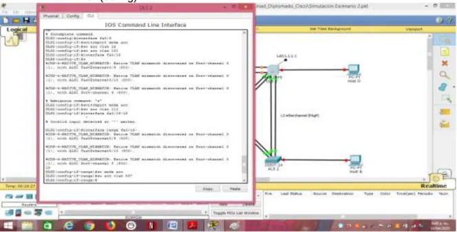
%CDP-4-NATIVE_VLAN_MISMATCH: Native VLAN mismatch discovered on FastEthernet0/9 (1), with ALS1 FastEthernet0/9 (800).
%CDP-4-NATIVE_VLAN_MISMATCH: Native VLAN mismatch discovered on FastEthernet0/10 (1), with ALS1 FastEthernet0/10 (800).
%CDP-4-NATIVE_VLAN_MISMATCH: Native VLAN mismatch discovered on FastEthernet0/9 (1), with ALS1 Port-channel 3 (800).
69 DLS2(config)#exit
DLS2#
%SYS-5-CONFIG_I: Configured from console by console
DLS2#show etherchannel summary Flags: D - down P - in port-channel I - stand-alone s - suspended H - Hot-standby (LACP only) R - Layer3 S - Layer2
U - in use f - failed to allocate aggregator u - unsuitable for bundling
w - waiting to be aggregated d - default port
Number of channel-groups in use: 3 Number of aggregators: 3
Group Port-channel Protocol Ports
---+---+---+---
2 Po2(SU) LACP Fa0/7(P) Fa0/8(P) 3 Po3(SU) PAgP Fa0/9(P) Fa0/10(P) 12 Po12(RD) LACP Fa0/11(D) Fa0/12(D) DLS2#
70
4) Todos los puertos troncales serán asignados a la VLAN 800 como la VLAN nativa.
Usamos el comando, show interface trunk, en cada switch, para
verificar los puertos troncales. En DSL1
DLS1>enable
DLS1#show interface trunk
Port Mode Encapsulation Status Native vlan Po1 on 802.1q trunking 800
Po4 on 802.1q trunking 800
Port Vlans allowed on trunk Po1 1-1005
Po4 1-1005
Port Vlans allowed and active in management domain Po1 1
Po4 1
Port Vlans in spanning tree forwarding state and not pruned Po1 1
Po4 1 DLS1#
Ahora configuramos el comando switchport trunk native vlan 800
para asignar la vlan 800 como vlan nativa para todos los puertos troncales en todos los Switches, para el escenario 2 las interfaces que pertenecen a los port-channel son 1, 2, 3 y 4.
ALS1#configure terminal
Enter configuration commands, one per line. End with CNTL/Z. ALS1(config-if-range)#interface Po1
ALS1(config-if)#switchport trunk native vlan 800 ALS1(config-if)#exit
ALS1(config)#interface Po3
71
Figura. - 50. Configuración Vlan 800 como Vlan nativa ALS1.
DLS1#configure terminal
Enter configuration commands, one per line. End with CNTL/Z. DLS1(config-if-range)#interface Po1
DLS1(config-if)#switchport trunk native vlan 800 DLS1(config-if)#exit
DLS1(config)#interface Po4
72
Figura. - 51. Configuración Vlan 800 como Vlan nativa DLS1.
DLS2#configure terminal
Enter configuration commands, one per line. End with CNTL/Z. DLS2(config-if-range)#interface Po2
DLS2(config-if)#switchport trunk native vlan 800 DLS2(config-if)#exit
DLS2(config)#interface Po3
73
Figura. - 52. Configuración Vlan 800 como Vlan nativa DLS2.
ALS2#configure terminal
Enter configuration commands, one per line. End with CNTL/Z. ALS2(config-if-range)#interface Po2
ALS2(config-if)#switchport trunk native vlan 800 ALS2(config-if)#exit
ALS2(config)#interface Po4
74
Figura. - 53. Configuración Vlan 800 como Vlan nativa ALS2.
d. Configurar DLS1, ALS1, y ALS2 para utilizar VTP versión 3.
1) Utilizar el nombre de dominio UNAD con la contraseña cisco123
2) Configurar DLS1 como servidor principal para las VLAN. DLS1>enable
DLS1#configure terminal
Enter configuration commands, one per line. End with CNTL/Z. DLS1(config)#vtp mode server
75
Figura. - 54. Configuración DLS1, para VTP versión 3 dominio UNAD Password
123, como servidor principal..
3) Configurar ALS1 y ALS2 como clientes VTP.
Configuración como cliente VTP ALS1. ALS1>enable
ALS1#configure terminal
Enter configuration commands, one per line. End with CNTL/Z. ALS1(config)#vtp mode client
Setting device to vtp client mode. ALS1(config)#vtp domain UNAD Domain name already set to UNAD. ALS1(config)#vtp password cosco123
76
Figura. - 55. Configuración como cliente VTP ALS1.
Configuración como cliente VTP ALS2. ALS2>enable
ALS2#configure terminal
Enter configuration commands, one per line. End with CNTL/Z. ALS2(config)#vtp mode client
Setting device to vtp client mode. ALS2(config)#vtp domain UNAD Domain name already set to UNAD. ALS2(config)#vtp password cosco123
Setting device VLAN database password to cosco123 ALS2(config)#
77
e. Configurar en el servidor principal las siguientes VLAN:
Numero de VLAN
Nombre de VLAN Numero de VLAN
Nombre de VLAN
800 NATIVA 434 ESTACIONAMIENTO
12 EJECUTIVOS 123 MANTENIMIENTO
234 HUESPEDES 1010 VOZ
1111 VIDEONET 3456 ADMINISTRACION
Tabla. - 1. VLAN a configurar en servidor principal.
Según la anterior tabla, Tabla 1, se crean las VLAN en DLS1 con identificación y nombre
DLS1>enable
DLS1#configure terminal
78
Figura. - 57. Lista de VLAN en servidor principal DLS1.
79
Las VLAN para los Switch ALS1 y ALS2 se cran automáticamente como se muestra en las figuras 59 y 60 respectivamente.
Figura. - 59. Lista VLAN ALS1.
80
f. En DLS1, suspender la VLAN 434.
Figura. - 61. Suspensión VLAN 434 3n servidor principal.
g. Configurar DLS2 en modo VTP transparente VTP utilizando VTP versión 2, y configurar en DLS2 las mismas VLAN que en DLS1.
Figura. - 62. Configuración VTP modo transparente en DLS2. Configurar en DLS2 las mismas VLAN que en DLS1 DLS2#configure terminal
Enter configuration commands, one per line. End with CNTL/Z. DLS2(config)#vlan 800
DLS2(config-vlan)#name NATIVA DLS2(config-vlan)#vlan 12
81 DLS2(config-vlan)#vlan 234
DLS2(config-vlan)#name HUESPEDES DLS2(config-vlan)#vlan 111
DLS2(config-vlan)#name VIDEONET DLS2(config-vlan)#vlan 434
DLS2(config-vlan)#name ESTACIONAMIENTO DLS2(config-vlan)#vlan 123
DLS2(config-vlan)#name MANTENIMIENTO DLS2(config-vlan)#vlan 101
DLS2(config-vlan)#name VOZ DLS2(config-vlan)#vlan 345
DLS2(config-vlan)#name ADMINISTRACION DLS2(config-vlan)#
Figura. - 63. Configuración de VLAN tabla 1 en DLS2.
h. Suspender VLAN 434 en DLS2.
82
i. En DLS2, crear VLAN 567 con el nombre de CONTABILIDAD. La VLAN de CONTABILIDAD no podrá estar disponible en cualquier otro Switch de la red.
Figura. - 65. Creación de VLAN CONTABILIDAD en DLS2.
j. Configurar DLS1 como Spanning tree root para las VLAN 1, 12, 434, 800, 1010, 1111 y 3456 y como raíz secundaria para las VLAN 123 y 234.
DLS1#configure terminal
Enter configuration commands, one per line. End with CNTL/Z. DLS1(config)#spanning-tree vlan 1,12,434,800,101,345
DLS1(config)#spanning-tree vlan 1,12,434,800,101,111,345 root primary
DLS1(config)#spanning-tree vlan 123,234 root secondary DLS1(config)#
83
k. Configurar DLS2 como Spanning tree root para las VLAN 123 y 234 y como una raíz secundaria para las VLAN 12, 434, 800, 1010, 1111 y 3456.
DLS2>enable
DLS2#configure terminal
Enter configuration commands, one per line. End with CNTL/Z. DLS2(config)#spanning-tree vlan 123,234 root primary
DLS2(config)#spanning-tree vlan 12,434,800,101,111,345 root secondary
DLS2(config)#
Figura. - 67. Configuración DLS2 como spanning.
l. Configurar todos los puertos como troncales de tal forma que solamente las VLAN que se han creado se les permitirá circular a través de éstos puertos.
84
m. Configurar las siguientes interfaces como puertos de acceso, asignados a las VLAN de la siguiente manera:
Interfaz DLS1 DLS2 ALS1 ALS2
Interfaz Fa0/6 3456 12,1010 123,1010 234
Interfaz Fa0/15 1111 1111 1111 1111
Interfaz Fa0/16-18 567
Tabla. - 2. Interfaces a configurar como puertos de acceso asignados a las VLAN.
Configuración de interfaces en DLS1. DLS1>enable
DLS1#configure terminal
Enter configuration commands, one per line. End with CNTL/Z. DLS1(config)#spanning-tree vlan 1,12,434,800,101,111,345 DLS1(config)#spanning-tree vlan 1,12,434,800,101,111,345 root primary
DLS1(config)#spanning-tree vlan 123,234 root secondary DLS1(config)#interface fa0/6
DLS1(config-if)#switch mode acc DLS1(config-if)#switch acc vlan 345 DLS1(config-if)#interface fa0/15 DLS1(config-if)#switch mode acc DLS1(config-if)#switch acc vlan 111 DLS1(config-if)#exit
DLS1(config)#
85
Configuración de interfaces en ALS1. ALS1#configure terminal
Enter configuration commands, one per line. End with CNTL/Z. ALS1(config)#interface fa0/6
ALS1(config-if)#switch mode acc ALS1(config-if)#switch acc vlan 123 ALS1(config-if)#switch acc vlan 101 ALS1(config-if)#interface fa0/15 ALS1(config-if)#switch mod acc ALS1(config-if)#switch acc vlan 111 ALS1(config-if)#exit
DLS1(config)#
Configuración de interfaces en ALS2. ALS2>enable
ALS2#config
ALS2#configure terminal
Enter configuration commands, one per line. End with CNTL/Z. ALS2(config)#interface fa0/6
ALS2(config-if)#switch mode acc ALS2(config-if)#switch acc vlan 234 ALS2(config-if)#interface fa0/15 ALS2(config-if)#switch accvlan 111 % Invalid input detected at '^' marker. ALS2(config-if)#switch acc vlan 111 ALS2(config-if)#
Configuración de interfaces en DLS2. DLS2>ena
DLS2#config ter
Enter configuration commands, one per line. End with CNTL/Z. DLS2(config)#spanning-tree vlan 123.234 root primary
DLS2(config)#spanning-tree vlan 12,434,800,101,111,345 root secondary
DLS2(config)#interface fa0/6
86
DLS2(config-if-range)#switch acc vlan 567 DLS2(config-if-range)#exit
ALS2(config)#
Figura. - 69. Figura. - 68. Configuración interfaces en DLS2 tabla 2. Parte 2: conectividad de red de prueba y las opciones configuradas.
a. Verificar la existencia de las VLAN correctas en todos los switches y la asignación de puertos troncales y de acceso.
87
Figura. - 71. Verificación existencia VLAN en DLS1.
88
Figura. - 73. Verificación existencia VLAN en ALS2.
b. Verificar que el EtherChannel entre DLS1 y ALS1 está configurado correctamente.
89 Figura. - 75. Verificación EtherChannel ALS1.
91
92
CONCLUSIONES
EN todo emprendimiento es básico e imperante exponer las habilidades aprendidas, por ello en nuestro caso, estudiantes de la Universidad Nacional Abierta y a Distancia, expongo en consideración en este documento las habilidades aprendidas en el Diplomado de Profundización CISCO CCNP, enfatizado en el enrutamiento dinámico de datos utilizando protocolos de comunicación adecuados para maximizar los recursos de la red con un mínimo uso de elementos de hardware.
Dichas habilidades aprendidas consisten en configurar una red de comunicación utilizando protocolos de comunicación adecuados, implementar direccionamiento y enrutamiento de direcciones IP bajo protocolos de comunicaciones, OSPF, PAgP y DSL, utilizando topología de red, tecnológicamente adecuada para llevar a cabo una comunicación acorde con las necesidades de la compañía.
Tomando como base los escenarios, (2), propuestos para el desarrollo y aplicación práctica de las habilidades apropiadas desde la plataforma CISCO, donde se aplican todos los conocimientos y habilidades obtenidas durante el diplomado.
Toda vez que es un documento de carácter ilustrativo, queda abierta la disposición de investigar sobre los temas abordados en el mismo para profundizar sobre los diferentes temas del documento.
Es de vital importancia, para el Ingeniero Electrónico, el conocimiento y la habilidad sobre las redes de comunicación, por cuanto todos los elementos de hardware utilizados en los sistemas de comunicación son elementalmente electrónicos.