TRAFFIC ANALYSIS AND SYNTHETIC SCENARIO GENERATION FOR ATM
OPERATIONAL CONCEPTS EVALUATION
Juan A. Besada, Javier Portillo, Gonzalo de Miguel, Rafael de Andrea, U. Politécnica de Madrid,
Madrid, Spain
Jose M. Canino, U. de Las Palmas de Gran Canaria, Las Palmas, Spain
Abstract
This paper describes a pair of systems which can be used to obtain realistic traffic samples in a Sector/TMA from a given real traffic database. Those are a Traffic Analyzer and a Traffic Pattern Generator. These two systems allow the ATM engineer to both gain insight on the traffic structure of the area under analysis and to obtain statistically significant samples for the evaluation of operational concepts and procedure changes, perform analysis of ATM performance under traffic changes, …
Introduction
With the advent of new ATM paradigms such as Trajectory Based Operations and the evolution in Collaborative Decision Making, changing roles of pilot and controller… it is important to have realistic traffic simulations to design and validate new ATM operational concepts. It is especially important now, with the rapid changes appearing in SESAR and NextGen projects.
In this paper we will describe a pair of systems with can be used to obtain realistic traffic samples from a given real traffic database. Those are a Traffic Analyzer and a Synthetic Traffic Generator.
Traffic Analyzer, taking the real flight information file and some additional information, obtains the patterns (statistical, determinist, or mixed), to be further used as a possible input to the Traffic Pattern Generator block.
Traffic Pattern Generator generates the information about the initial conditions of the aircraft to be considered in the simulation exercise, including preferred trajectory and dynamic state. It produces
Synthetic traffic file with the generated aircraft features and flight plans associated. This file is to be used in a realistic simulation to define traffic scenario under analysis.
The paper will describe those systems in detail, their related HMIs enabling for a comprehensive analysis of the traffic under analysis, and for graphical validation of the generated traffic.
There are systems similar to these, such as Eurocontrol Traffic Sample Generator (TSG) [1], or TRAFGEN, within PITOT by AENA[2] and similar efforts, based in modifications of recorded data, has been published recently [3]. Many of the systems for scenario preparation are based on real traffic cloning or deletion by a human user. This is a very costly and error-prone method.
Please note in the current definition of those systems they are oriented to the analysis/simulation of TMA traffic, although many of the concepts involved may be extrapolated to the simulation of en-route sectors or to other geographical areas. This work is a MATLAB® prototype that has been developed for INDRA under Spanish ATLANTIDA[4] project, and it will surely become a tool integrated in near future INDRA ATM product line.
High Level System Description
The main objective of the traffic analyzer and generator is to produce a file with the information of the flight initial conditions to be generated in a specific spatial distribution (in a TMA). It is important to note that the final output of the synthetic traffic generator is not the time evolution of the real flights, but the initial information necessary (i.e. initial conditions and flight plans) to feed an ATM simulator (either a real time or a fast time simulator).
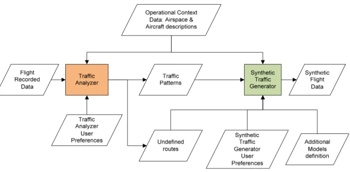
Figure 1. Block diagram of the Analyzer and Synthetic Traffic Generator
Next, a brief explanation of the blocks in the figure is presented.
Traffic Analyzer
Traffic analyzer, taking the real flight information file and additional information, obtains the patterns (statistical, determinist, or mixed), to be further used as a possible input to the Traffic Pattern Generator block. The information input / output to this block is:
• Real traffic data. It is a file with the information of real flights to analyze. The pattern analyzer to extract the traffic patterns will examine this information. • Operational context: These files contains
the TMA physical structure: Entry points (STARs starting points), STARs (waypoint list), TMA exit points (SID ends and starting of overfly routes), SID (waypoint list), domestic routes, airports, … In addition, some characteristics of aircraft are included in a set of aircraft types files, to be used for classification of flights.
• User preferences for the analysis. This is another file containing the information necessary to define the analysis preferences. It will contain a pair of flags indicating if the traffic analysis must try to obtain deterministic traffic patterns or not, and if the traffic analysis must include the analysis of overfly flights; a set of thresholds used to define if the pattern under analysis has a deterministic form or not; a list of special days where the traffic does not follow the same pattern as others due to special circumstances (public holidays, long weekends…); and a polar grid used to group airports outside of the TMA with similar geographic location.
It produces the following information (which could, potentially, be input of traffic generator):
GUI, and it could also be edited to adapt system behavior to desired traffic patterns. • Undefined routes: they are a description of
routes followed by traffic but not described in the operational context definition.
Synthetic Traffic Generator
This block generates the information about the initial conditions of the aircraft to be considered in the simulation exercise, as a starting point to the real traffic generation (trajectories) realized by the following units. The information input / output to this block is:
• Operational context: The same input as traffic analyzer.
• Undefined routes: As provided by traffic analyzer.
• Models to generate traffic: As we have mentioned before, instead of using the patterns extracted by the pattern analyzer, the user could replace them (or a part of them) with user-defined parameters. It could be useful, for instance, to perform a controlled change of the traffic generation parameters (i.e., an aircraft arrival rate to a TMA entry point) in order to see the effects in the simulation exercises.
• Additional Models to generate traffic: Some traffic features cannot be extracted from the real traffic file analysis, and must be directly provided by the user.
• User preferences for the generation: Those are some additional parameters to be used at generator, such as: the time interval to be used for generation; a list of special days where the traffic does not follow the same pattern as others due to special circumstances (public holidays, long weekends…); a set of traffic validation thresholds; the flight duration between injection time and arrival to TMA; and the minimum time separation at entry points. It produces the following information: • Synthetic traffic generated initial data. A
file with the generated aircraft features and flight plans associated.
Detailed Functionality of Traffic
Pattern Analyzer
This section is a detailed description of the functions comprising the traffic pattern analyzer. First of all, we should comment a general feature of the traffic patterns. It is reasonable to suppose that an important part of the traffic in the TMA (both arrivals and departures) will have an important deterministic component. Many of the arrival and departure flights will repeat on a daily basis with the same flight plan. Superposed on that deterministic pattern there will exist a random pattern which will not follow such a predictable model.
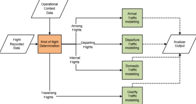
Taking into account the preceding paragraph, we propose to consider the following traffic pattern analysis model (see Figure 2):
• Mixed model. In this case, the traffic pattern analyzer will extract the parameters of a model that has a deterministic and a random part. We will generate the deterministic part considering the regularity of flights (i.e., we will analyze a number of similar weeks and extract the deterministic pattern for each weekday). The random part of the model will be analyzed after extracting the deterministic part.
• Probabilistic model. In this case, the analyzer performs a bypass of the deterministic model estimation functions and treats the entire database file in order to obtain probabilistic functions for all the necessary functions.
In order to describe the functions, we will assume we have a database with a number of representative flight weeks enough to perform an accurate estimation of the traffic functions and their parameters.
There are four different kinds of flights to be included in the traffic model:
• Arrival Flights. • Departure Flights.
• Domestic Flights (Internal to TMA). • Overfly flights (those with an origin and
destination airports out of the TMA).
Slightly different models must be defined for each of those types, and all those models will be provided in a unique analyzer output. We will detail the functionality for arrival traffic.
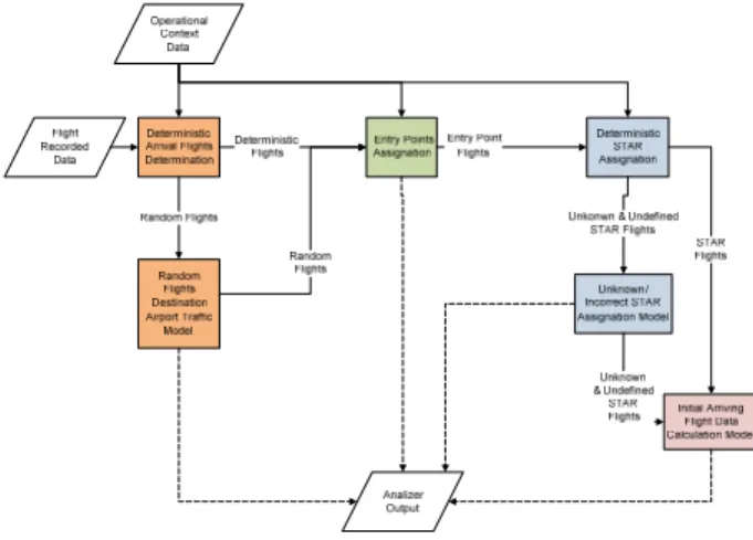
Arrival Traffic Analysis
This function has four stages, related to identification of deterministic/random flight patterns arrival to an airport, assignation of entry point and STAR, and modeling of initial conditions of arrival aircraft (see Figure 3).
Figure 3. Traffic Analyzer for Arrival Aircraft These functions will be detailed next.
Deterministic Arrival Flights Determination
This function will obtain the deterministic pattern of incoming flights. From the analysis of the input flight database, a deterministic pattern of flights with an ETA and destination airport may be inferred. In order to estimate the deterministic component, the function will perform a flight identification and ETA
correlation over the database information in order to detect repetition patterns of flights in the following cases (with a threshold related to a given percentage of occurrences):
• Every day of the week • Several days of the week • One day of the week
• Special days marked by the user
We will group origin airports using a polar grid with respect to TMA center, so that all airports in a cell of that grid will be equivalent. A logarithmic law will define ranges defining the grid. Each cell in the grid will be treated as a common origin.
In addition we assume deterministic flights have a distribution of aircraft types associated, with a discrete probabilistic law associated, which will be estimated. We will have an equivalence of aircraft types from the aircraft table, so that we can aggregate equivalent aircraft.
The information extracted by the deterministic component will be a list of deterministic flights, with:
• Flight Identification • Origin (grid cell) • Destination airport • ETA to the airport
• Repetition pattern, one of the four cases previously considered.
• Aircraft type list: For each aircraft type used for this flight:
o Identifier of the type o Percentage of entrances
Once the deterministic components are obtained, with the remaining information, the random component of the traffic model will be estimated. Please note this function may be bypassed if only probabilistic models are to be estimated.
Random Flights Destination Airport Model Extraction
stationary process, we will calculate this per hour, and there could be different distributions for:
• Different days of the week.
• Special days, to be marked by the user. • Different Origins: as defined in 0.
• Different Aircraft Types: We will have an equivalence (based on a wake vortex turbulence, engine count, engine type and ICAO aircraft description) of aircraft types from the aircraft table, so that we can aggregate equivalent aircraft.
Those three aspects are correlated. The approach used to perform this estimation is:
• Perform a segmentation of flights by destination airport, origin and aircraft type. • Perform a segmentation of days by day of
week and special day’s table. Each of those segments is what we will call a day type.
• For each destination airport, origin airport cell, aircraft type and day type, we will calculate the average number of arrival flights per hour. This is the only parameter needed for the generation of the arrival traffic model.
Entry Points Assignation
This function will take the information of all flights and find deterministic patterns about the TMA entry points of the flights with a determined origin and destination airport. Please remember that origins are grouped using the airport grid. If there is more than one potential entry point for a given pair of origin and destination airport, we will obtain a discrete probability distribution function and its associate parameters (percentages related to each entry point) to model the TMA entry point assignation. So there will be a table with:
• Origin airport cell • Destination Airport • Aircraft Type Class
• Entry point list: For each entry point o Identification
o Percentage of entrances
There will be a percentage threshold, so that if only a very small amount of flights do not follow the
deterministic pattern we will assume the assignation is deterministic and the model will not take into account those non-deterministic flights, treating them as outliers.
STAR Assignation
This function will take the information of all flights and find deterministic patterns about the STAR used by the flights with a determined entry point and destination airport. If there are more than one potential STAR for a given pair entry point-destination airport, we will obtain a discrete probability distribution function and its associate parameters (percentages related to each STAR) to model the STAR assignation. So there will be a table with:
• Entry point
• Destination Airport • Aircraft Type Class • STAR list: For each STAR
o Identification
o Percentage of entrances
There will be another outlier percentage threshold for this assignation.
Undefined & Unknown STAR Assignation Model Extraction
Sometimes, the flights could follow a route not considered by the STAR definition. If this is the case, we must define a pseudo-STAR for those routes, and perform an analysis similar to the STAR extraction but taking into account those pseudo-STARs, in addition to the nominal ones. So there will be a table with:
• Entry point
• Destination Airport • Aircraft Type Class • STAR list: For each STAR
o Identification (pseudo-STAR identification, provided by the analyzer)
o Percentage of entrances
This will be provided in an independent file to be appended to the operational context model of the traffic generator.
Initial Arrival Flight Data Calculation Model Now we consider the way to estimate model for the arrival flight initial conditions. Please note each kind of flight (arrival, departure, domestic and overfly) will have its own initial data calculation procedure, as different data is needed for the injection of each kind of flight in a simulation.
We will estimate the components of several probability distribution function (estimated from the data) and its corresponding parameters:
• Cruise velocity (corresponding to entry point fix). There will be a distribution different for each origin, destination airport within the TMA, and aircraft type. • Entry point altitude (corresponding to
entry fix point). There will be a distribution different for each origin, destination airport within the TMA, and aircraft type.
• In order to calculate the time of injection at simulation, we will model it as the subtraction of several terms:
o ETA, which will be obtained at generation time from the deterministic pattern of from the random arrival pattern.
o Landing delay, which is the time difference between the ETA and the actual landing time. This is an additive term. There will be a distribution estimated per origin airport cell, destination airport, entry point and aircraft type. o Duration of flight inside the
TMA (difference between entry fix point and landing time, which is last fix time). This is a subtractive term. It should be necessary to perform a segmentation of this item per STAR, and per aircraft type, and obtain a distribution for each of those sets.
o Duration of flight prior to entrance in TMA. This is another subtractive term. This will be a user-defined time constant. No calculation related to this term will be performed during analysis.
Detailed Functionality of Synthetic
Traffic Generator
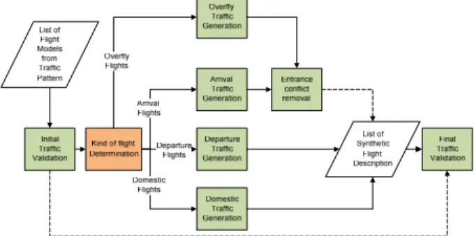
The traffic generator will use a traffic pattern description file and produce a set of synthetic flights consistent with that description. Traffic pattern description file contains a list of deterministic and probabilistic patterns (with respect to several different aspects such as flight periodicity, route or significant points), and this method will parse the description of such a pattern and produce a flight or set of flights consistent with this pattern. The whole list of synthetic flights is obtained as an aggregation of the flights generated based on all those patterns.
Figure 4. Synthetic Traffic Generator.
As the models used to generate arrival, departure, domestic and overfly flights are different, and the data provided for each of those patterns are different, generation is divided for those same types of flights.
Generation will be performed for a contiguous time interval, which could be:
• A set of hours
• A complete day (of predefined type with respect to traffic patterns).
• A set of consecutive days (of predefined types with respect to traffic patterns), up to a complete year.
Initial Traffic Validation
This function will check if the requested traffic pattern is within certain operational limits, defined by the user. Adding all traffic patterns in each operational context element, we will check the following limits:
• Airport number of operations per hour. • Entry point number of operations per hour. • Exit point number of operations per hour. • TMA traffic per hour. In this case, we will
sum all traffic domestic to TMA. This will be compared with a threshold.
• Entry Points check. This function checks that all Entry point identifiers in the traffic patterns are described in the Operational Context input file.
If any of those thresholds is exceeded, or there is an unknown entry point, we will stop generation, and inform about the problematic traffic pattern.
Arrival Flights
This part of the generator is in charge of creating arrival flights according to the arrival flight traffic patterns. There will be a similar function for departure, domestic and overfly flights. We will detail only this kind of flights processing see Figure 5).
Figure 5. Synthetic Traffic Generator for Arrivals
This is performed in a set of steps where we consecutively refine the information regarding individual flights or groups of flights. In the following diagrams the (D?) symbol stands for a test where we are working with a flight or group of flights either deterministic or not with respect to the next step in the refinement.
Next we will detail each of those functions in the following subsections.
Deterministic Destination Airport Selection
This function will select and generate the deterministic pattern of incoming flights. Using the information of the flight model traffic pattern file, obtained by the traffic analyzer, the deterministic pattern of flights with an ETA and destination airport will be selected. This selection will include the repetition patterns of flights in the following cases:
• Every day of the week. • Several days of the week. • One day of the week.
• Special days marked by the user
So first the system will need to decide if the given day is of any of those previous types, and perform an aggregation of the deterministic traffic patterns of all the sets the current day belongs to.
The information generated by the deterministic destination airport selection will be a list of flights. Each of those flights will have:
• Flight Identification
• Origin: defined using the grid defined in the analyzer.
• Destination airport • ETA to the airport
• Aircraft Type Class: Identifier of the aircraft type class, generated using the discrete probability function of aircraft type classes estimated in the analysis phase as a combination of aircraft’s Description, Engine Type, Engine Count and WTC.
Random Flights Destination Airport Model Generation
origin airport cells (using the airport grid), aircraft type and day type, and for each hour we will generate the number of flights with all those conditions following the previously defined arrival process. Each flight will have:
• Flight Identification (Synthetic) • Origin.
• Destination airport.
• ETA to the airport (obtained using the Poisson process).
• Aircraft Type Class.
Deterministic Entry Point Assignation
This function will select and generate the information about the deterministic TMA entry points of the flights with a determined origin, destination airport and Aircraft Type Class. So, for a flight whose origin and destination airport are related to a deterministic entry point (one with 100% occurrence according to flight pattern entrance), we will complete the flight with the corresponding deterministic entry point. Therefore, now, for each flight we will have:
• Flight Identification (Synthetic) • Origin.
• Destination airport. • ETA to the airport. • Aircraft Type Class. • Entry point.
Probabilistic Entry Points Assignation Model Extraction
In the case of flights with a given origin, destination airport and Aircraft Type Class that use several TMA entry points, we will use a discrete probability distribution function and its associate parameters (percentages related to each entry point) to generate the TMA entry point assignation. Therefore, now, for each flight we will also have:
• Flight Identification (Synthetic) • Origin.
• Destination airport. • ETA to the airport. • Aircraft Type Class. • Entry point.
Deterministic STAR Assignation
This function will select and generate the deterministic patterns about the STAR used by the flights with a determined entry point, destination airport and Aircraft Type Class. So, for a flight whose entry point and destination airport are related to a deterministic STAR (one with 100% occurrence according to flight pattern), we will complete the flight with the corresponding deterministic STAR. Therefore, now, for each flight we will have:
• Flight Identification (Synthetic) • Origin.
• Destination airport. • ETA to the airport. • Aircraft Type Class. • Entry point.
• STAR.
Please note that with respect to this point undefined STARS are equivalent to defined STARS. Probabilistic STAR Assignation Model Extraction
In the case of flights with a given entry point, destination airport and Aircraft Type Class that use several STARs, we will use a discrete probability distribution function and its associate parameters (percentages related to each STAR) to generate the STAR assignation. Therefore, now, for each flight we will have:
• Flight Identification (Synthetic) • Origin.
• Destination airport. • ETA to the airport. • Aircraft Type Class. • Entry point.
• STAR.
Please note that with respect to this point undefined STARS are equivalent to defined STARS. Initial Arrival Flight Data Calculation Model
• Aircraft Type. Identifier of the type, generated using the discrete probability function of aircraft types estimated in the analysis phase for this aircraft type class identifier.
• Cruise velocity (corresponding to entry fix point ). We will generate a value from the analyzer provided distribution for each origin, destination airport within the TMA, and aircraft type
• Entry point altitude (corresponding to entry fix point ). We will generate a value from the analyzer provided distribution for each origin, destination airport within the TMA, and aircraft type.
• In order to generate the time of injection at simulation, we will subtract several terms. Flight initialization will be performed to ensure arrival to entry point at the predefined time: (ETA+Landing Delay- Duration of flight inside the TMA):
o ETA, which will be generated from the deterministic pattern of from the random arrival pattern. o Landing delay, which is the time
difference between the ETA and the actual landing time. This is an additive term. We will use the adequate distribution estimated for origin airport cell, destination airport, and aircraft type. We will use the distribution provided by analyzer.
o Duration of flight inside the TMA (difference between entry point fix and landing time, which is last fix time). This is a subtractive term. We will use the adequate distribution estimated for STAR and aircraft type. We will use the distribution provided by analyzer.
o Duration of flight prior to entrance in TMA. This is a subtractive term. This will be a user-defined time constant. • We will assume a flight at constant height,
heading and speed, converging towards the
TMA, injected at the previously defined time instant. The heading will be calculated assuming the flight came directly from the center of the origin cell to the entry point following a constant heading trajectory. We will calculate the initial position for the injection assuming this flight pattern and predicting back in time entry point position by duration of flight prior to entrance in TMA term. • In addition, In order to be able to perform
accurate predictions of aircraft trajectory, we must calculate aircraft weight at initial position and performance model to be used. It is obtained through the following approximate algorithm. From a set of simplified tables with weights and performances for different heights (Consumption per minute for different flight segments) we could obtain reasonable weights for the aircraft. The defined method is based on the exploitation of BADA[5] data. Aircraft weight Minitial is calculated as:
Minitial =Mdest(h,d)
+ROFCruise(cruise_altitude)* Texc +Mmin+r*Mpyld
where:
o Mdest(h,d) is the estimated mass of the fuel needed to fly to the destination airport.
o h is the entry point altitude o d is the distance travelled inside
the TMA (from the entry point to the airport)
o ROFcruise,low(h) is the cruise rate of fuel consumption of height h, with low weight.
o ROFdescend(h) is the cruise rate of fuel consumption of height h o cruise_altitude is the en route
cruise altitude.
or decreases of consumption along flight. It will have a mean of 100 and a variance given in additional flight model definition file
o M100 is the estimated fuel needed for 100 minutes of overflying (ROFCruise(cruise_altitude)*(100) o Mmim is the minimum mass of
the aircraft as defined in BADA. o Mpyld is the payload mass of the
aircraft as defined in BADA. o r is a sample of a uniform
random variable from
Min_Ocupation to Max_Ocupation (parameters
defined in additional flight model definition file).
• Mdest(h,d) is the fuel consumption needed to arrive from injection point to airport, calculated using the next algorithm (based on a table similar to that of PTF BADA files):
o First we shall compute the time needed to descent from FLi+1 to FLi, using a vertical speed of ROCDi, to be Tdesc(i).
T
desc(
i
)
=
FL
i+1−
FL
iROCD
i*100
o Then we can compute the fuelspent to descend from height h to airport level (assumed to be zero), as:
( )
∑
=
=
h FL
o i
desc descend
nom
desc h ROF i T i
M _ ( ) ()* ()
o If we assume we are descending at the nominal true airspeed VTASdescend(i) between FLi+1 and FLi ,the traversed distance during the complete nominal descend will be:
∑
== h
o i
desc descend
nom
desc h VTAS i T i
d _ ( ) ()* ()
o If we assume we are prior to descend we are at level flight at the nominal true airspeed, and Tprev is the duration of flight prior to entrance in TMA (user defined time constant), the complete weight will be:
Mdest(h,d)=ROFCruise,low(h)
*Tprev+
d−ddesc_nom(h)
VTAScruise(h)
⎛ ⎝
⎜ ⎞
⎠
⎟ +Mdesc_nom(h)
Entrance Conflict Removal
After aggregating arrival and overfly flights, there should be a test to see if there is a potential conflict at any entry point. If this is the case, there should be a modification in injection times of conflicting aircraft, so that they are separated.
Conflict detection will be performed assuming a minimum time difference at entry point.
Conflict resolution will be performed increasing time injection of the last aircraft to arrive to the airport until there is no conflict. Please note this could induce a new conflict in the entry point, so there should be a recursive solution for this problem obtaining conflict free traffic.
Final Traffic Validation
This function will recheck if the generated traffic pattern is within the operational limits defined by the user. We will allow for a 10% additional guard, so that even not completely compliant traffic is allowed. The following limits will be checked against thresholds.
• Airport number of operations per hour. • Entry point number of operations per hour. • Exit point number of operations per hour. • TMA traffic per hour.
If any of those thresholds is exceeded, we will not save generated flights, and inform about the problematic traffic pattern.
Traffic Analyzer and Generator HMI
Next we will summarize the input and output HMIs of both Traffic Analyzer and Traffic Generator. Special emphasis is given to output HMIs, due to the fact that they are the means to be used by the operator to either understand the traffic situation or to validate the generated scenario.
Traffic Analyzer Input HMI
This interface allows for the selection of XML files including traffic data, operational context definition, aircraft type and aircraft type class definition, and to edit a user preferences file or select a preciously generated user preferences file. Once all those files are provided, it has a button to invoke traffic analysis.
Traffic Pattern Analyzer Output HMI
Next we will consider the presentation of the results of the analysis module. There are means for the representation of aggregated data and pattern related data.
Aggregated Traffic Data
The analysis module will represent different views of traffic. There are two result presentation modes:
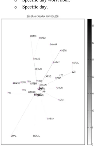
• Traffic Map: The user select a time interval to present the results, and a time increment, and the software shows, using a color code, the number of aircraft passing through each leg in each time interval (aggregated from all flight types and adding deterministic flights and the mean number of random flights), as shown in Figure 6. Several different representations may be done in this mode:
o Normal days average hour. o Normal days average day. o Normal days average week. o Normal days worst hour. o Normal days worst day. o Special days average hour. o Special days average day. o Specific hour.
o Specific day average hour.
o Specific day worst hour. o Specific day.
Figure 6. Example of Traffic Map
• Number of flights plot: The user selects a scenario element (SID, STAR, entry point, exit point, airport, etc) and a plot of the evolution of number of aircraft versus time (per hour) is shown (see Figure 7). The user will be able to define one of the following time intervals
o Average day (24 hours): It will perform the average of the desired traffic for all days, separated by hour.
o Worst day (24 hours): It will find the highest of the desired traffic for all days, separated by hour. There should be a method to select an hour and obtain details of the worst day.
o Worst Week (7 days x 24 hours): It will find the highest of the desired traffic for all days, separated by hour. It will be represented using seven number of flights plots, one per day in the week. There should be a method to select an hour and day and obtain details of the worst week.
o Special days (24 hours): It will find the highest of the desired traffic for all days, separated by hour.
o Specific day (24 hours): It will show the traffic for this day, separated by hour.
o Specific week (7 days x 24 hours): It will show the traffic for this week, separated by hour. It will be represented using seven number of flights plots, one per day in the week.
Figure 7. Example of Number of Flights Plot for Specific Day
The user will be able to aggregate/discriminate data over the following set of items:
• Type of flight: Arrival, Departure, Domestic, Overfly, or All Data (aggregated)
• TMA element: TMA, SID, STAR, Domestic route, Overfly route, Entry Point, Exit Point, Leg, Waypoint, Origin Airport, Destination Airport, Origin Cell, Destination Cell.
• Type of pattern: Deterministic, Random (we will use the mean number of flights in the random pattern), Total (aggregation of deterministic and random)
Deterministic Pattern Data
The system will allow for search of a specific flight number, and will provide a means to show its pattern data:
• Origin and Destination: Airports/Airport cells depending on the type of flight
• ETA/Departure Time/Entrance time model: Expected Time of Arrival to the airport/Departure from airport/Entrance to TMA time model depending on the type of flight
• Repetition Pattern: one of the four cases (Every day of the week, Several days of the week (specify which ones), one day of the week (specifying which one), Special days)
• Aircraft Types: Set of pairs (Designator of an aircraft type of this class, Percentage of entrances for associated Aircraft Type Class)
Additional Traffic Data
Additional data from the analysis must be visible to the user. It will be a method to show in a tabular manner data in the traffic pattern file:
• Arrival Pattern:
o Entry point assignation. o STAR Assignation.
o Cruise velocity distributions o Entry point distributions
o Landing delay model
distributions • Departure Pattern:
o Exit point assignation. o SID Assignation.
o Departure delay model
• Domestic pattern
o Route Assignation.
o Departure delay model
distributions. • Overfly pattern
o Entry Point Assignation o Exit Point Assignation o Overfly route Assignation o Cruise velocity distributions o Entry point distributions
Synthetic Traffic Generator Input HMI
This interface allows for the selection of XML files including traffic pattern data, additional model data, operational context definition, aircraft type and aircraft type class definition, and to edit a user preferences file or select a previously generated user preferences file. Once all those files are provided, it has a button to invoke traffic generation.
Synthetic Traffic Generator Output HMI
Next we will consider the presentation of the results of the generator module.
Aggregated Traffic Data
The generation module will represent different views of traffic, by aggregating all flights. All data is derived from generated flights, not from generator inputs.
There are two result presentation modes: • Traffic Map: The user select a time
interval to present the results, and a time increment, and the software shows, using a color code, the number of aircraft passing through each leg in each time interval (aggregated from all flight types and adding deterministic flights and the mean number of random flights. The representation is quite similar to that of the analysis, but with slightly different cases. • Number of flights plot: The user selects a
scenario element (SID, STAR, entry point, exit point, airport, etc) and a plot of the evolution of number of aircraft versus time (per hour) is shown, as in the analysis, but calculated by counting individual
generated flights. The user will be able to define one of the following time intervals
o Average day (24 hours): It will perform the average of the desired traffic for all days, separated by hour.
o Average Week (7 days x 24 hours): It will perform the average of the desired traffic for all weeks, separated by hour. It will be represented using seven number of flights plots, one per day in the week.
o Specific day (24 hours): It will show the traffic for this day, separated by hour.
o Specific week (7 days x 24 hours): It will show the traffic for this week, separated by hour. It will be represented using seven number of flights plots, one per day in the week.
The user will be able to aggregate/discriminate data over the following set of items:
• Type of flight: Arrival, Departure, Domestic, Overfly, or All Data (aggregated)
• TMA element: TMA, SID, STAR, Domestic route, Overfly route, Entry Point, Exit Point, Leg, Waypoint, Origin Airport, Destination Airport, Origin Cell, Destination Cell.
Detailed Traffic Data
There will be a means to provide, in a tabular manner, the data regarding the generated flights for a given time interval.
The provided data will be different for the different kinds of flights, and comprises all the information needed for flight simulation.
Conclusions and Future Work
• Validation and refinement of traffic models with experts (controllers, ATM engineers, …). Special emphasis should be given to the search of potential correlations among distributions of different flight aspects.
• Completion of prototype HMI development.
• Inclusion of company related fields, as company preferences will have a clear impact on final trajectory.
• Adaptation of prototype to INDRA ATM commercial products.
• Research on potential means of exploitation of the tool.
References
[1] Integra-TSG Web page
[2] AENA-PITOT Web page
[3] R. Oaks, S. Liu, D. Zhou, M. Paglione, W. J. Hughes. Methodology for the generation air traffic scenarios based on recorded traffic data. DASC 2003. Indianapolis.
[4] ATLANTIDA Web page
[5] BADA Eurocontrol Web page