TítuloDesign and Evaluation of new waveforms for high mobility communications
203
0
0
Texto completo
(2) Deseño e Avaliación de Novas Formas de Onda para Comunicacións de Alta Mobilidade. Tomás Domínguez Bolaño Tese de Doutoramento UDC / 2018. Directores:. Luis Castedo Ribas José Antonio García Naya. Programa de Doutoramento en Tecnoloxías da Información e das Comunicacións en Redes Móbiles.
(3) Diseño y Evaluación de Nuevas Formas de Onda para Comunicaciones de Alta Movilidad. Tomás Domínguez Bolaño Tesis Doctoral UDC / 2018. Directores:. Luis Castedo Ribas José Antonio García Naya. Programa de Doctorado en Tecnologías de la Información y de las Comunicaciones en Redes Móviles.
(4) Tomás Domínguez Bolaño. CERTIFICA / CERTIFICA / CERTIFIES. Que a presente memoria é o resultado do meu propio traballo de investigación e que o traballo doutros autores está citado axeitadamente. Que la presente memoria es el resultado de mi propio trabajo de investigación y que el trabajo de otros autores está citado apropiadamente. That the present report is the result of my own research work and that the work done by other authors is appropriately cited.. A Coruña, setembro de 2018 / septiembre de 2018 / September 2018. Tomás Domínguez Bolaño.
(5) Luis Castedo Ribas José Antonio García Naya CERTIFICAN / CERTIFICAN / CERTIFY Que a presente tese titulada “Deseño e avaliación de novas formas de onda para comunicacións de alta mobilidade” foi realizada por Tomás Domínguez Bolaño baixo a nosa dirección no Departamento de Enxeñaría de Computadores da Universidade da Coruña e preséntase para obter o grao de Doutor. Que la presente tesis titulada “Diseño y evaluación de nuevas formas de onda para comunicaciones de alta movilidad” fue realizada por Tomás Domínguez Bolaño bajo nuestra dirección en el Departamento de Ingeniería de Computadores de la Universidade da Coruña y se presenta para obtener el grado de Doctor. That the present thesis titled “Design and evaluation of new waveforms for high mobility communications” was done by Tomás Domínguez Bolaño under our supervision in the Department of Computer Engineering at the University of A Coruña and it is submitted to obtain the Ph.D. degree. Os directores da tese / Los directores de la tesis / The Ph.D. supervisors. A Coruña, setembro de 2018 / septiembre de 2018 / September 2018.. Dr. Luis Castedo Ribas Catedrático de Universidade Dpto. de Enxeñaría de Computadores Universidade da Coruña. Dr. José Antonio García Naya Prof. Contratado Doutor Dpto. de Enxeñaría de Computadores Universidade da Coruña. Full Professor Dept. of Computer Engineering University of A Coruña. Ph.D. Associate Professor Dept. of Computer Engineering University of A Coruña.
(6) Tese de Doutoramento / Tesis Doctoral / Doctoral Thesis. Título:. Deseño e avaliación de novas formas de onda para comunicacións de alta mobilidade. Título:. Diseño y evaluación de nuevas formas de onda para comunicaciones de alta movilidad. Title:. Design and evaluation of new waveforms for high mobility communications. Autor / Autor / Author:. Tomás Domínguez Bolaño. Directores / Directores / Supervisors:. Luis Castedo Ribas José Antonio García Naya. Data / Fecha / Date:. setembro de 2018 / septiembre de 2018 / September 2018. Tribunal / Tribunal / Evaluation Committee. Presidente / Presidente / President:. Vogal / Vocal / Member:. Secretaria / Secretaria / Secretary:. Markus Rupp. Xuefeng Yin. Paula M. Castro Castro.
(7) To my family.
(8) Acknowledgements I want to express my gratitude to my PhD advisors, Luis Castedo and José Antonio. Luis Castedo was also the advisor of my bachelor’s thesis, and once finished, he gave me the opportunity to work at the GTEC these last 4 years. I thank José Antonio for all his invaluable support and effort during all these years, without which this thesis could not have been finished. In the last four years I was fortunate to be able to work with Xose, I have to thank him also for all the support and help during these years. It is also thanks to him that this thesis has come to fruition. The last year, Xose decided to leave for a postdoc position at Tongji University (China, Shanghai). Thanks to that I was able to carry out a 4-month research stay there. Xosé’s support was essential during the stay, not only for research purposes, but also for logistics. I also want to thank Yin Xuefeng, my supervisor at Tongji university. I also thank the students with whom I worked in China for all the good times that we had: Xuesong, Xiaokang, Liuyuan, Jingxiang, Sibo, Zeyu, Yejian, Kai, Hui, Chao and Le. I will always remember the measurement campaigns with the drone, in which we worked very hard. I also thank my colleagues of the GTEC Lab, for all the help and good times during the last years: Pedro, Óscar, Ángel, Valentín, Manuel, Paula, José Francisco and José Pablo. Finally, I thank my mother for all her support.. i.
(9) Resumo Os servizos multimedia e de datos experimentaron un crecemento continuo nos últimos anos e espérase que crezan aínda máis nos anos seguintes. A xente está a usar cada vez máis os seus dispositivos móbiles para acceder a servizos baseados en datos para fins relacionados co traballo, entretemento ou socialización en liña. Ademais, as comunicacións masivas de tipo máquina tamén están en ascenso (por exemplo, as comunicacións en transporte e loxística, sensores, Internet das cousas, etc.), e serán moi importantes para a nova xeración de sistemas de comunicacións sen fíos. Para afrontar o aumento esperado no uso de servizos multimedia e baseado en datos, así como para soportar novos casos de uso que hoxe non son posibles, unha nova xeración de redes sen fíos é necesaria. Para iso, espérase que os sistemas de comunicación sen fíos 5G traian as melloras necesarias: maiores taxas de datos, baixas latencias, mellor eficiencia enerxética, alta fiabilidade, etc. O coñecemento das características da canle sen fíos é fundamental para a planificación das redes de comunicación sen fíos e o deseño de transceptores. Como primeiro paso, centramos este traballo na caracterización completa da canle para diferentes escenarios, como son os trens de alta velocidade, metro e comunicacións vehículo a infraestrutura en estradas. A canle caracterizouse mediante a avaliación da relación sinal a ruído, a perda de traxecto (path loss) e os chamados parámetros condensados da canle (por exemplo, o factor K, o perfil potencia-retardo (power delay profile) e a densidade espectral de potencia Doppler. Ademais, para a nova interface aérea das redes 5G, unha das principais cuestións foi a forma de onda a usar. Finalmente, o 3rd Generation Partnership Project (3GPP) decidiu usar a tecnoloxía de multiplexación por división de frecuencias ortogonais (OFDM polas súas siglas en inglés). Isto semella unha elección natural debido ás moitas vantaxes de OFDM e que tamén é a técnica de modulación empregada nas redes 4G. Con todo, nos últimos anos, esquemas multiportadora baseados en bancos de filtros (FBMC polas súas siglas en inglés) recibiron unha grande atención como alternativa a OFDM debido ás súas vantaxes: non utilizan un prefixo cíclico (proporcionan unha maior eficiencia espectral), os usuarios non precisan ser sincronizados no enlace ascendente, e un mellor rendemento teórico en contornas de alta velocidade debido a unha menor interferencia entre portadoras. Neste traballo comparamos experimentalmente o rendemento de FBMC e OFDM en contornas de alta velocidade. Tamén analizamos o rendemento de FBMC e OFDM no caso de uso práctico dun vehículo aéreo lixeiro pilotado remotamente. A maior parte do traballo realizado nesta tese requiriu o deseño e desenvolvemento do chamado GTEC 5G Simulator, que foi usado en conxunto co GTEC Testbed para realizar a maior parte das campañas de medicións e avaliacións de rendemento mediante transmisións polo aire.. ii.
(10) Resumen Los servicios multimedia y basados en datos experimentaron un crecimiento sin interrupciones en los últimos años, y se espera que crezcan aún más en los años siguientes. Las personas utilizan cada vez más sus dispositivos móviles para acceder a los servicios basados en datos con fines relacionados con el trabajo, el entretenimiento o la socialización en línea. Además, las comunicaciones masivas de tipo máquina también están en aumento (por ejemplo, comunicaciones en transporte y logística, sensores, Internet de las cosas, etc.) y serán muy importantes para la nueva generación de sistemas de comunicaciones inalámbricos. Para hacer frente al aumento esperado en el uso de servicios multimedia y basados en datos, así como para soportar nuevos casos de uso que no son posibles hoy en día, se requiere una nueva generación de sistemas inalámbricos. Para esto, se espera que los sistemas de comunicación inalámbrica 5G aporten las mejoras necesarias: mayores tasas de datos, menores latencias, mejor eficiencia energética, alta fiabilidad, etc. El conocimiento de las características del canal inalámbrico es fundamental para la planificación de redes de comunicación inalámbricas y el diseño de transceptores. Como primer paso, centramos este trabajo en la caracterización completa del canal para diferentes escenarios, tales como trenes de alta velocidad, metro y comunicaciones vehículo a infraestructura en carreteras. El canal se caracterizó por medio de la evaluación de la relación señal a ruido, la pérdida de trayecto (path loss) y los llamados parámetros condensados de canal (por ejemplo, el factor K, el perfil potencia-retardo (power delay profile) y la densidad espectral de potencia Doppler). Además, para la nueva interfaz aérea de las redes 5G, una de las preguntas principales ha sido la forma de onda a usar. Finalmente, el 3rd Generation Partnership Project (3GPP) decidió usar la tecnología de multiplexación por división de frecuencias ortogonales (OFDM por sus siglas en inglés). Esta es una elección lógica, debido a las muchas ventajas exhibidas por OFDM y dado que también es la técnica de modulación empleada en las redes 4G. Sin embargo, en los últimos años, los esquemas multiportadora basados en bancos de filtros (FBMC por sus siglas en inglés) han recibido una gran atención como una alternativa a OFDM debido a sus ventajas: no usan un prefijo cíclico (lo que proporciona una mayor eficiencia espectral), los usuarios no necesitan sincronizarse en el enlace ascendente, y un mejor rendimiento teórico en escenarios de alta velocidad debido a una menor interferencia entre subportadoras. En este trabajo comparamos experimentalmente el rendimiento de FBMC y OFDM en entornos de alta velocidad. También analizamos el rendimiento de FBMC y OFDM en el caso de uso práctico de un vehículo aéreo ligero tripulado remotamente. La mayor parte del trabajo llevado a cabo en esta tesis requirió el diseño y desarrollo del denominado GTEC 5G Simulator, que se utilizó junto con el GTEC Testbed para realizar la mayoría de las campañas de medidas y evaluaciones de rendimiento por medio de transmisiones por aire.. iii.
(11) Abstract Multimedia and data-based services experienced a non-stopping growth over the last few years and are expected to grow even more in the following years. People are using more and more their mobile devices to access data-based services for work-related purposes, entertainment or online socialization. Moreover, massive machine-type communications are also on the rise (e.g., transport and logistics communications, sensors, Internet of Things, etc.), and will be very important for the new generation of wireless communication systems. To cope with the expected increase in the usage of multimedia and data-based services, as well as to support new use cases which are not possible today, a new generation of wireless systems is required. For this, 5G wireless communication systems are expected to bring the necessary improvements: higher data rates, lower latencies, better energy efficiency, high reliability, etc. Knowledge of the wireless channel characteristics is fundamental for the planning of wireless communication networks and transceivers design. As a first step, this work centered in the channel characterization for different scenarios such as high-speed trains, subways, and vehicle-to-infrastructure in roads. The channel was characterized by means of assessing the signal-to-noise ratio, the path loss, and the so-called channel condensed parameters (e.g., the K-factor, the power delay profile, and the Doppler power spectral density). Moreover, for the new air interface of 5G networks, one of the main questions was the waveform to be used. Finally, the 3rd Generation Partnership Project (3GPP) decided to use orthogonal frequencydivision multiplexing (OFDM). This seems a natural choice due to the many advantages exhibited by OFDM and it is also the modulation technique employed by 4G networks. However, over the last few years, schemes based on filter bank multicarrier (FBMC) using quadrature amplitude modulation have received a great attention as an alternative to OFDM due to their advantages: they do not use a cyclic prefix (thus providing a higher bandwidth efficiency), users do not need to be synchronized in the uplink, and they achieve a theoretical better performance in high-speed scenarios due to a lower inter-carrier interference. In this work, we have experimentally compared the performance of FBMC versus OFDM in high-speed scenarios. We have also analyzed the performance of FBMC versus OFDM in the practical use case of a lightweight remotely piloted aircraft. The majority of the work carried out in this thesis required the design and development of the so-called GTEC 5G Simulator, which was used in conjunction with the GTEC Testbed to perform most of the measurement campaigns and performance evaluations by means of over-the-air transmissions.. iv.
(12) Table of Contents 1. Introduction 1.1 Thesis Overview . . . . . . . . . . . . . . . . . . . . . . . . . . . . . . . . . 1.2 Thesis Methodology and Resources . . . . . . . . . . . . . . . . . . . . . . . 1.3 Co-authored Publications . . . . . . . . . . . . . . . . . . . . . . . . . . . . .. 2. The GTEC Testbed and the GTEC 5G Simulator 2.1 Introduction . . . . . . . . . . . . . . . . . . . . . . . . 2.2 The GTEC Testbed . . . . . . . . . . . . . . . . . . . . 2.2.1 Hardware . . . . . . . . . . . . . . . . . . . . . 2.2.2 Software . . . . . . . . . . . . . . . . . . . . . 2.3 The GTEC 5G Simulator . . . . . . . . . . . . . . . . . 2.3.1 Overall Description of the Simulator . . . . . . . 2.3.2 Structure of the Simulator . . . . . . . . . . . . 2.3.3 Configuration of Parameters and Constants . . . 2.3.4 Transmitter . . . . . . . . . . . . . . . . . . . . 2.3.5 Channel Model . . . . . . . . . . . . . . . . . . 2.3.6 Receiver . . . . . . . . . . . . . . . . . . . . . 2.4 Executing Simulations . . . . . . . . . . . . . . . . . . 2.4.1 Simulations Iterating over Several Noise Values . 2.4.2 Simulations Iterating over Several Speed Values . 2.5 Measurements Methodology . . . . . . . . . . . . . . . 2.5.1 Offline Processing . . . . . . . . . . . . . . . . 2.5.2 Measurements . . . . . . . . . . . . . . . . . . 2.6 Conclusions . . . . . . . . . . . . . . . . . . . . . . . .. 3. Experimental Characterization of 2.6 GHz LTE Wireless Trains 3.1 Introduction . . . . . . . . . . . . . . . . . . . . . . . . 3.2 Experimental Setup . . . . . . . . . . . . . . . . . . . . 3.2.1 Measurement Environment . . . . . . . . . . . . 3.2.2 Measurement Equipment . . . . . . . . . . . . . v. . . . . . . . . . . . . . . . . . .. . . . . . . . . . . . . . . . . . .. . . . . . . . . . . . . . . . . . .. . . . . . . . . . . . . . . . . . .. . . . . . . . . . . . . . . . . . .. . . . . . . . . . . . . . . . . . .. . . . . . . . . . . . . . . . . . .. . . . . . . . . . . . . . . . . . .. . . . . . . . . . . . . . . . . . .. . . . . . . . . . . . . . . . . . .. . . . . . . . . . . . . . . . . . .. . . . . . . . . . . . . . . . . . .. 1 3 5 5 8 8 9 9 11 12 12 13 13 15 17 17 18 18 19 21 22 22 23. Links in High-Speed . . . .. . . . .. . . . .. . . . .. . . . .. . . . .. . . . .. . . . .. . . . .. . . . .. . . . .. . . . .. 24 25 27 28 29.
(13) 3.3. 3.4 3.5. 3.6 3.7 4. 5. 3.2.3 Measurement Procedure . . . . . . . Signal Processing at the Receiver . . . . . . . 3.3.1 Synchronization in LTE . . . . . . . 3.3.2 Channel Response Estimation . . . . 3.3.3 SNR Estimation . . . . . . . . . . . Path Loss Estimation . . . . . . . . . . . . . Estimation of Channel Condensed Parameters 3.5.1 K-factor . . . . . . . . . . . . . . . . 3.5.2 Power Delay Profile . . . . . . . . . 3.5.3 Doppler Power Spectral Density . . . Particularities of the Measured Train Scenario Conclusions . . . . . . . . . . . . . . . . . .. . . . . . . . . . . . .. . . . . . . . . . . . .. . . . . . . . . . . . .. . . . . . . . . . . . .. . . . . . . . . . . . .. . . . . . . . . . . . .. . . . . . . . . . . . .. . . . . . . . . . . . .. . . . . . . . . . . . .. . . . . . . . . . . . .. . . . . . . . . . . . .. . . . . . . . . . . . .. . . . . . . . . . . . .. . . . . . . . . . . . .. . . . . . . . . . . . .. . . . . . . . . . . . .. . . . . . . . . . . . .. . . . . . . . . . . . .. 32 34 35 35 40 40 43 43 44 46 48 54. Experimental Characterization of 2.6 GHz LTE Wireless Links in a Modern Subway Station 4.1 Introduction . . . . . . . . . . . . . . . . . . . . . . . . . . . . . . . . . . . . 4.2 Experimental Setup . . . . . . . . . . . . . . . . . . . . . . . . . . . . . . . . 4.2.1 Measurement Environment . . . . . . . . . . . . . . . . . . . . . . . . 4.2.2 Measurement Equipment and Procedure . . . . . . . . . . . . . . . . . 4.3 Receiver Signal Processing . . . . . . . . . . . . . . . . . . . . . . . . . . . . 4.4 Measurement Results . . . . . . . . . . . . . . . . . . . . . . . . . . . . . . . 4.4.1 Path Loss Estimation . . . . . . . . . . . . . . . . . . . . . . . . . . . 4.4.2 Power Delay Profile . . . . . . . . . . . . . . . . . . . . . . . . . . . 4.4.3 Root Mean Square Delay Spread . . . . . . . . . . . . . . . . . . . . . 4.4.4 Doppler Power Spectral Density . . . . . . . . . . . . . . . . . . . . . 4.4.5 Mean-Centered Doppler Power Spectral Density . . . . . . . . . . . . 4.4.6 Small-Scale Fading Analysis . . . . . . . . . . . . . . . . . . . . . . . 4.4.7 K-factor Analysis . . . . . . . . . . . . . . . . . . . . . . . . . . . . . 4.5 Conclusions . . . . . . . . . . . . . . . . . . . . . . . . . . . . . . . . . . . .. 56 57 60 60 62 64 66 67 69 73 75 78 81 84 85. Vehicle-to-Infrastructure Channel Characterization Based on LTE Measurements 5.1 Introduction . . . . . . . . . . . . . . . . . . . . . . . . . . . . . . . . . . . . 5.2 Experimental Setup . . . . . . . . . . . . . . . . . . . . . . . . . . . . . . . . 5.2.1 Measurement Scenario . . . . . . . . . . . . . . . . . . . . . . . . . . 5.2.2 Measurement Procedure . . . . . . . . . . . . . . . . . . . . . . . . . 5.3 Measurement Results . . . . . . . . . . . . . . . . . . . . . . . . . . . . . . . 5.3.1 Signal-to-Noise Ratio . . . . . . . . . . . . . . . . . . . . . . . . . . 5.3.2 Power Delay Profile . . . . . . . . . . . . . . . . . . . . . . . . . . . 5.3.3 Doppler Power Spectral Density . . . . . . . . . . . . . . . . . . . . . 5.3.4 Root Mean Square Delay Spread . . . . . . . . . . . . . . . . . . . . .. 87 87 88 88 91 92 92 93 94 95. vi.
(14) 5.4 6. 7. 8. 5.3.5 Diversity Gain . . . . . . . . . . . . . . . . . . . . . . . . . . . . . . 97 Conclusions . . . . . . . . . . . . . . . . . . . . . . . . . . . . . . . . . . . . 100. Experimental Evaluation of FBMC 6.1 Introduction . . . . . . . . . . . . . . . . . . . . . . . 6.2 Introduction to FBMC . . . . . . . . . . . . . . . . . 6.3 FBMC Evaluation in Quasi-static Environments . . . . 6.3.1 Testbed Setup . . . . . . . . . . . . . . . . . . 6.3.2 Measurement Scenarios . . . . . . . . . . . . 6.3.3 Evaluation Procedure . . . . . . . . . . . . . . 6.3.4 Simulation Results . . . . . . . . . . . . . . . 6.3.5 Measurement Results . . . . . . . . . . . . . . 6.4 FBMC Evaluation in High-Speed Environments . . . . 6.4.1 Simulation Results . . . . . . . . . . . . . . . 6.4.2 Emulating High Speeds by Time Interpolation . 6.4.3 Measurement Setup and Procedure . . . . . . . 6.4.4 Different Channel Realizations . . . . . . . . . 6.4.5 Measurement Results . . . . . . . . . . . . . . 6.5 Conclusions . . . . . . . . . . . . . . . . . . . . . . .. . . . . . . . . . . . . . . .. . . . . . . . . . . . . . . .. . . . . . . . . . . . . . . .. . . . . . . . . . . . . . . .. . . . . . . . . . . . . . . .. . . . . . . . . . . . . . . .. . . . . . . . . . . . . . . .. . . . . . . . . . . . . . . .. . . . . . . . . . . . . . . .. . . . . . . . . . . . . . . .. . . . . . . . . . . . . . . .. . . . . . . . . . . . . . . .. Air-to-Ground Communications with Lightweight Remotely Piloted Aircrafts 7.1 Introduction . . . . . . . . . . . . . . . . . . . . . . . . . . . . . . . . . . . 7.2 Measurement Environment and Procedure . . . . . . . . . . . . . . . . . . . 7.2.1 Measurement Equipment . . . . . . . . . . . . . . . . . . . . . . . . 7.2.2 Measurement Scenarios and Flight Routes . . . . . . . . . . . . . . . 7.2.3 Transmit Signals . . . . . . . . . . . . . . . . . . . . . . . . . . . . 7.3 OFDM/FBMC Measurements Results . . . . . . . . . . . . . . . . . . . . . 7.3.1 Results for OFDM Signals . . . . . . . . . . . . . . . . . . . . . . . 7.3.2 Results for FBMC Signals . . . . . . . . . . . . . . . . . . . . . . . 7.3.3 Effects of the Flight Height . . . . . . . . . . . . . . . . . . . . . . . 7.3.4 Results for Vertical Flights . . . . . . . . . . . . . . . . . . . . . . . 7.4 Conclusions . . . . . . . . . . . . . . . . . . . . . . . . . . . . . . . . . . . Conclusions and Future Work 8.1 Conclusions . . . . . . . . . . . . . . . . . . 8.2 Future Work . . . . . . . . . . . . . . . . . . 8.2.1 High-Speed Train Channel Modeling 8.2.2 High-Speed Emulation . . . . . . . . 8.2.3 Air-to-Ground Communications with Aircrafts . . . . . . . . . . . . . . . vii. . . . . . . . . . . . . . . . . . . . . . . . . . . . . . . . . . . . . . . . . . . . . . . . . . . . . Lightweight Remotely . . . . . . . . . . . . .. . . . . . . . . . . . . . . .. 102 103 104 107 108 109 111 112 113 115 116 116 118 121 123 132. . . . . . . . . . . .. 134 134 135 136 137 140 141 142 146 148 150 153 155 155 158 158 158. . . . . . . . . . . . . . . . . . . . . Piloted . . . . . 159.
(15) 8.2.4. 5G Communication Systems . . . . . . . . . . . . . . . . . . . . . . . 159. Appendices. 160. A Resumen de la Tesis A.1 Caracterización Experimental de Canales de Comunicaciones sin Hilos . A.1.1 Trenes de Alta Velocidad . . . . . . . . . . . . . . . . . . . . . . A.1.2 Estación Moderna de Metro . . . . . . . . . . . . . . . . . . . . A.1.3 Escenario Vehículo a Infraestructura . . . . . . . . . . . . . . . . A.2 Evaluación Experimental del Rendimiento de FBMC . . . . . . . . . . . A.2.1 Entornos de Alta Velocidad . . . . . . . . . . . . . . . . . . . . A.2.2 Comunicaciones Aire-Tierra con un Vehículo Aéreo no Tripulado. 160 161 161 162 164 165 165 166. B List of Acronyms. . . . . . . .. . . . . . . .. . . . . . . .. 168. References. 171. viii.
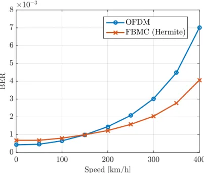
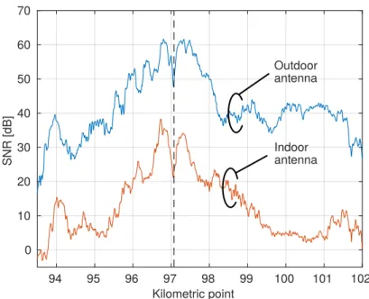
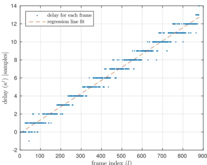
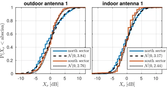
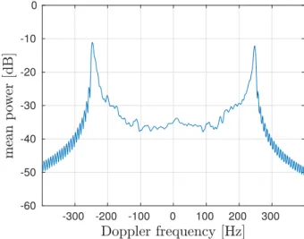
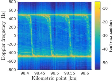
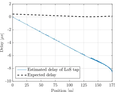
(16) List of Figures 2.1 2.2 2.3 2.4 2.5 2.6 2.7. GTEC Testbed structure . . . . . . . . . . . . . . . . . . . . . . . . . . . . . Picture of the USRP™ B210 board. . . . . . . . . . . . . . . . . . . . . . . . Block diagram of a node of the GTEC Testbed. . . . . . . . . . . . . . . . . . GTEC Testbed node acting as a transmitter. . . . . . . . . . . . . . . . . . . . GTEC 5G Simulator structure for performing simulations. . . . . . . . . . . . GTEC 5G Simulator transmitter structure. . . . . . . . . . . . . . . . . . . . . Examples of frame structures for orthogonal frequency-division multiplexing (OFDM) and filter bank multicarrier (FBMC). . . . . . . . . . . . . . . . . . . 2.8 GTEC 5G Simulator receiver structure. . . . . . . . . . . . . . . . . . . . . . 2.9 BER versus Eb /N0 for the TUx channel model. . . . . . . . . . . . . . . . . . 2.10 BER versus emulated speed for OFDM and FBMC with Hermite prototype filter, TUx channel model and Eb /N0 = 30 dB. . . . . . . . . . . . . . . . . . 2.11 Measurement process using the GTEC 5G Simulator. . . . . . . . . . . . . . . 3.1 3.2 3.3 3.4 3.5 3.6 3.7 3.8 3.9 3.10 3.11 3.12 3.13 3.14 3.15 3.16 3.17. Map of the scenario considered for the measurements. . . . . . . . . . . . . . . Séneca laboratory train (Talgo A-330). . . . . . . . . . . . . . . . . . . . . . . Pictures of the GSM-R site. . . . . . . . . . . . . . . . . . . . . . . . . . . . . Radiation pattern for the transmit antennas. . . . . . . . . . . . . . . . . . . . Onboard measurement equipment. . . . . . . . . . . . . . . . . . . . . . . . . Estimated SNR versus KP for one of the indoor and one of the outdoor antennas. Synchronization signals for FDD LTE. . . . . . . . . . . . . . . . . . . . . . . Exemplary results of delays for a portion of the captured frames. . . . . . . . . Received energy and least-squares fitting. . . . . . . . . . . . . . . . . . . . . Cumulative probabilities of Xσ . . . . . . . . . . . . . . . . . . . . . . . . . . Estimated K-factor for outdoor antenna 1. . . . . . . . . . . . . . . . . . . . . Estimated PDP for outdoor antenna 1. . . . . . . . . . . . . . . . . . . . . . . Normalized power delay profile (PDP) for outdoor antenna 1. . . . . . . . . . . Estimated root mean square (RMS) Delay Spread. . . . . . . . . . . . . . . . . Doppler Spectrum for outdoor antenna 1. . . . . . . . . . . . . . . . . . . . . Doppler Spectrum for outdoor antenna 1. . . . . . . . . . . . . . . . . . . . . Detailed view of the train infrastructure. . . . . . . . . . . . . . . . . . . . . . ix. 10 10 10 11 13 15 16 17 19 21 22 28 29 30 30 32 33 34 38 41 42 43 44 45 46 47 49 50.
(17) 3.18 Normalized PDP for outdoor antenna 1. . . . . . . . . . . . . . . . . . . . . .. 51. 3.19 Estimated Doppler power spectral density (PSD) for outdoor antenna 1. . . . .. 52. 3.20 Condensed parameters for outdoor antenna 1 at 200 km/h. . . . . . . . . . . . .. 53. 4.1. Schematic of the measurement scenario at “La Almudena” subway station. . . .. 58. 4.2. Picture taken from the train cabin while conducting measurements. . . . . . . .. 59. 4.3. GTEC Testbed nodes and antennas used in the measurements. . . . . . . . . .. 60. 4.4. SNR for the eNodeB-train and eNodeB-mobile links. . . . . . . . . . . . . . .. 62. 4.5. Antenna radiation patterns. . . . . . . . . . . . . . . . . . . . . . . . . . . . .. 63. 4.6. Estimated delay of the line-of-sight (LoS) path for the Evolved Node B (eNodeB)-train link, antenna 1, before correction as indicated in Eq. (4.2). . . .. 65. Estimated delay of the LoS path for the eNodeB-train link, antenna 1, after correction as indicated in Eq. (4.2). . . . . . . . . . . . . . . . . . . . . . . . .. 66. 4.8. Gain for the eNodeB-train and eNodeB-mobile links. . . . . . . . . . . . . . .. 68. 4.9. PDP scatter plot for the eNodeB-train link (antenna 1). . . . . . . . . . . . . .. 70. 4.10 PDP scatter plot for the eNodeB-mobile link (antenna 1). . . . . . . . . . . . .. 70. 4.11 Normalized mean PDP (antenna 1). . . . . . . . . . . . . . . . . . . . . . . .. 72. 4.12 RMS delay spread (antenna 1). . . . . . . . . . . . . . . . . . . . . . . . . . .. 74. 4.13 CDF of the delay spread (antenna 1) and fittings. . . . . . . . . . . . . . . . .. 74. 4.14 Doppler PSD for the eNodeB-train link (antenna 1). . . . . . . . . . . . . . . .. 77. 4.15 Doppler PSD for the eNodeB-mobile link (antenna 1). . . . . . . . . . . . . .. 77. 4.16 Mean-centered Doppler PSD for the eNodeB-train link (antenna 1). . . . . . .. 78. 4.17 Mean-centered Doppler PSD for the eNodeB-mobile link (antenna 1). . . . . .. 79. 4.18 Normalized mean-centered Doppler PSD (antenna 1). . . . . . . . . . . . . . .. 80. 4.19 Received power for a single frequency f0 = 0 both for eNodeB-train and eNodeB-mobile links. . . . . . . . . . . . . . . . . . . . . . . . . . . . . . . .. 81. 4.7. 4.20 CDF and fittings of the small-scale fading for the eNodeB-train link (antenna 1). 83 4.21 CDF and fittings of the small-scale fading for the eNodeB-mobile link (antenna 1). . . . . . . . . . . . . . . . . . . . . . . . . . . . . . . . . . . . . . . . . .. 84. 4.22 AIC weights considering small signal windows. . . . . . . . . . . . . . . . . .. 84. 4.23 K-factor for both the eNodeB-train and the eNodeB-mobile links (antenna 1). .. 85. 5.1. Mobile unit equipped with four omni-directional receive antennas mounted on a car and base-station with an X-pol transmit antenna panel. . . . . . . . . . .. 89. Measurement scenario: base-station transmitter and the path followed by the car based on the collected Global Positioning System (GPS) data. . . . . . . .. 89. 5.3. Speed of the car along the path according to the GPS data. . . . . . . . . . . .. 90. 5.4. TD-LTE single-antenna downlink transmitter. . . . . . . . . . . . . . . . . . .. 90. 5.5. Radiation pattern for the horizontal element of the transmit antenna. . . . . . .. 90. 5.2. x.
(18) 5.6 5.7 5.8 5.9 5.10 5.11 5.12 5.13 5.14 5.15. TD-LTE uplink-downlink configuration pattern considered in the measurements for the 10 LTE subframes composing a 10 ms LTE frame. . . . . . . . . . . . . 91 SNR versus the position of the car along the measurement path. . . . . . . . . 93 PDP for antenna 1 along the measurement path. . . . . . . . . . . . . . . . . . 93 Normalized mean PDP for antenna 1. . . . . . . . . . . . . . . . . . . . . . . 94 Doppler PSD for antenna 1. . . . . . . . . . . . . . . . . . . . . . . . . . . . . 95 Delay Spread for antenna 1. . . . . . . . . . . . . . . . . . . . . . . . . . . . . 96 CDF of delay spread for antenna 1 and sections 1, 2, and 3. . . . . . . . . . . . 96 Gain improvements for sections 2 and 3. . . . . . . . . . . . . . . . . . . . . . 97 Diversity gain for Sections 2 and 3 and maximum ratio combining (MRC). . . . 99 Diversity gain for sections 2 and 3. . . . . . . . . . . . . . . . . . . . . . . . . 100. 6.1 6.2 6.3 6.4 6.5 6.6 6.7 6.8 6.9 6.10 6.11 6.12 6.13 6.14 6.15 6.16 6.17 6.18 6.19 6.20 6.21 6.22. FBMC and OFDM pulses. . . . . . . . . . . . . . . . . . . . . . . . . . . . . 107 Block diagram of the performance evaluation setup. . . . . . . . . . . . . . . . 107 PDP and frequency response of TUx, IBx and PAx channel models. . . . . . . 108 Map of the medium-sized office and corridor scenarios. . . . . . . . . . . . . . 110 Map and picture of the small office scenario. . . . . . . . . . . . . . . . . . . . 110 Picture of the medium-sized office scenario with LoS. . . . . . . . . . . . . . . 110 Picture of the corridor scenario with the receiver moving at 3 km/h. . . . . . . 111 BER versus Eb /N0 for the different considered channel models. . . . . . . . . 113 BER versus Eb /N0 for the measurements in four different scenarios. . . . . . . 114 BER versus speed for Eb /N0 = 30 dB for the different considered channel models.115 Example of spectrum compression due to a time interpolation factor I = 2. . . 116 FBMC/OFDM dual-antenna receiver nodes mounted on a car. . . . . . . . . . 118 Measurement scenario with the car trajectory and the location of the base station. 119 Single-antenna base station. . . . . . . . . . . . . . . . . . . . . . . . . . . . . 119 Measurement setup for the high-speed evaluations. . . . . . . . . . . . . . . . 119 Transmitted frame structure in function of the interpolation factor I. . . . . . . 120 Frame structure considered for the measurements. . . . . . . . . . . . . . . . . 120 BER vs SNR for FBMC using the Hermite prototype filter. . . . . . . . . . . . 122 BER vs SNR for the minimum and the maximum emulated speeds considered. . 122 EVM vs SNR for the minimum and the maximum emulated speeds considered. 124 BER vs emulated speed for an SNR value of 23 dB. . . . . . . . . . . . . . . . 125 Coded and uncoded BER versus SNR for the minimum and maximum emulated speeds for FBMC (Hermite case) and 2-PAM constellation. . . . . . . . . . . . 125 6.23 Coded and uncoded BER versus SNR for the minimum and maximum emulated speeds for FBMC (Hermite case) and 4-PAM constellation. . . . . . . . . . . . 126 6.24 Coded and uncoded BER versus SNR for the minimum and maximum emulated speeds for FBMC (Hermite case) and 8-PAM constellation. . . . . . . . . . . . 126 xi.
(19) 6.25 Coded bit error rate (BER) versus SNR for FBMC (8-PAM) and OFDM (64QAM), the maximum emlated speed, and the highest coding rate. . . . . . . . . 6.26 Coded and uncoded BER versus Eb /N0 for the minimum and maximum emulated speeds for FBMC (Hermite case) and 4-PAM constellation. . . . . . . 6.27 Throughput versus SNR for the minimum and maximum emulated speeds. All the modulation schemes are shown. . . . . . . . . . . . . . . . . . . . . . . . 6.28 Throughput versus emulated speed for different SNR values. . . . . . . . . . . 6.29 Throughput versus SNR for the minimum and maximum emulated speeds. . . . 6.30 Relative contribution per constellation and code rate to the total throughput. . . 6.31 Relative contribution per constellation and code rate to the total throughput. . . 7.1 7.2 7.3 7.4 7.5 7.6 7.7 7.8 7.9 7.10 7.11 7.12 7.13 7.14 7.15 7.16 7.17 7.18. Block diagram of the measurement setup. . . . . . . . . . . . . . . . . . . . . Picture of the air part of the measurement equipment . . . . . . . . . . . . . . Ground part of the measurement devices . . . . . . . . . . . . . . . . . . . . . Measurement Scenario I . . . . . . . . . . . . . . . . . . . . . . . . . . . . . Measurement Scenario II . . . . . . . . . . . . . . . . . . . . . . . . . . . . . Picture of the UAV close to the landing point . . . . . . . . . . . . . . . . . . Frame structure considered for the measurements. . . . . . . . . . . . . . . . . SNR for horizontal flights at low-altitude values. . . . . . . . . . . . . . . . . Uncoded BER for horizontal flights at low-altitude values (omnidirectional antenna). . . . . . . . . . . . . . . . . . . . . . . . . . . . . . . . . . . . . . . Uncoded BER for horizontal flights at low-altitude values (directional antenna). Coded BER for horizontal flights at low-altitude values. . . . . . . . . . . . . . Throughput for horizontal flights at low-altitude values . . . . . . . . . . . . . Uncoded BER comparison between OFDM and FBMC for horizontal flights at low-height values (omnidirectional antenna). . . . . . . . . . . . . . . . . . . . Throughput comparison between OFDM and FBMC for horizontal flights at low-height values (omnidirectional antenna). . . . . . . . . . . . . . . . . . . . Power Spectral Density for OFDM and FBMC transmit signals. . . . . . . . . SNR for horizontal flights at different heights. . . . . . . . . . . . . . . . . . . Throughput for horizontal flights at different height.s . . . . . . . . . . . . . . SNR and throughput for vertical flights at different horizontal distances. . . . .. xii. 127 128 129 129 130 130 131 136 137 137 138 138 139 140 142 143 144 145 146 147 148 149 150 151 152.
(20) List of Tables 3.1 3.2 3.3 3.4. Ground antennas orientation. . . . . . . . . . . . . . . . . . LTE testbed configuration parameters. . . . . . . . . . . . . Long Term Evolution (LTE) signal configuration parameters. Estimated path loss parameters. . . . . . . . . . . . . . . . .. . . . .. 31 31 36 43. 4.1 4.2 4.3 4.4. FDD-LTE testbed configuration parameters. . . . . . . . . . . . . . . . . . . . Path loss estimated parameters for the double breakpoint model (estimating d1 ). Path loss estimated parameters for the single breakpoint model. . . . . . . . . . RMS delay spread distribution fittings and 90 % value of CDF for the eNodeBtrain link. . . . . . . . . . . . . . . . . . . . . . . . . . . . . . . . . . . . . . RMS delay spread distribution fittings and 90 % value of CDF for the eNodeBmobile link. . . . . . . . . . . . . . . . . . . . . . . . . . . . . . . . . . . . . AIC weights obtained for the small-scale fading. . . . . . . . . . . . . . . . .. 62 67 68. LTE-TDD parameters used in the measurements. . . . . . . . . . . . . . . . . Delay spread lognormal fittings (µ, σ) for all the antennas and sections. . . . . Diversity gain mean and variance—expressed in natural units— for the different sections, combining methods, and antenna combinations. . . . . . . . . . . . . Excess path gain mean and variance—expressed in natural units—when a single antennas is selected. . . . . . . . . . . . . . . . . . . . . . . . . . . . . . . . .. 91 95. 4.5 4.6 5.1 5.2 5.3 5.4. . . . .. . . . .. . . . .. . . . .. . . . .. . . . .. . . . .. . . . .. . . . .. 75 75 83. 97 98. 6.1 6.2. Main parameters used in the experiments (static environment). . . . . . . . . . 112 Main parameters used in the experiments (high-speed environment). . . . . . . 121. 7.1 7.2 7.3 7.4. Height flight values for the different horizontal flights considered. . . . . Distance values for the vertical flights. . . . . . . . . . . . . . . . . . . . Parameters of the OFDM/FBMC transmit frames . . . . . . . . . . . . . Details of the modulation and coding schemes (MCSs) used for OFDM/FBMC signals. . . . . . . . . . . . . . . . . . . . . . . . . . . .. xiii. . . . . . . . . . the . . .. 139 140 140 141.
(21) Chapter I Introduction Multimedia and data-based services experienced a non-stopping growth over the last few years and are expected to grow even more in the following. People are using more and more their mobile devices to access data-based services for work-related purposes, entertainment or online socialization [SR16]. Moreover, massive machine-type communications (mMTC) are also on the rise (e.g., transport and logistics communications, sensors, Internet of things (IoT), etc.) and will be very important for the new generation of wireless systems. The fourth generation (4G) of wireless communications systems, using the Long Term Evolution (LTE) standards, have been commercially deployed since 2009. 4G systems following the international mobile telecommunications advanced (IMT-Advanced) requirements, as defined by ITU Radiocommunication Sector (ITU-R), provided a very large improvement over the previous third generation (3G). Some of the improvements included the increase of the peak data rate (for both low and high mobility situations), the ability to dynamically share and use the network resources, the usage of scalable channel bandwidths, and the increase of the spectral efficiency. However, in order to cope with the expected increase in the usage of multimedia and data-based services, as well as to support new use cases not possible today, a new generation of wireless systems is required. For this, the fifth generation (5G) wireless communication systems are expected to bring the necessary improvements, including higher data rates, lower latencies, a better energy efficiency, high reliability for communications, etc. 5G wireless systems will support three generic services [P OP +18]: • enhanced mobile broadband (eMBB): This service will be an evolution of the services already provided by 4G, providing stable connections with high peak data rates, low latencies, and moderate rates for users on the cell edges. In this service, different mobility classes are considered, ranging from stationary to high-speed mobility up to 500 km/h [ITU17]. • mMTC: this service is intended for sensors or IoT-like devices. It will support a high number of devices that can be active sporadically and send small data payloads. • ultra-reliable and low-latency communications (URLLC): this service is intended for lowlatency transmissions of small payloads with very high reliability. 1.
(22) 1. Introduction To make all these improvements possible, 5G will use a new physical layer interface defined by the 3rd Generation Partnership Project (3GPP) and known as new radio (NR), as well as a new core network architecture. One of the main effects impacting on wireless communications is the multipath propagation. In wireless communications, the signals reach the receiver from the transmitter following different paths. Usually, a direct line-of-sight (LoS) path exists, but also the signal will be reflected and diffracted by different objects in the environment. Different delayed multipath components are added up at the receiver, hence creating frequency-selective channels. One of the main tasks of a wireless receiver is to equalize the channel, i.e., undoing the effect of the channel on the signal. In this regard, multicarrier modulation techniques allow for solving this problem in a computationally effective way by dividing the channel frequency response into narrower sub-channels in which the frequency selectivity can be considered flat. More specifically, orthogonal frequency-division multiplexing (OFDM) is one of the most used multicarrier modulations today. Another important effect impacting on wireless communications is the Doppler effect, named after the Austrian physicist Christian Doppler, who postulated the effect in 1842. The movement of a receiver relative to the transmitter leads to a frequency shift of the received signal, which is called a Doppler shift. More specifically, each of the multipath components of the signal arriving at the receiver will experience a different Doppler shift depending on the relative angle of arrival with respect to the receiver. Also, as this effect depends on the speed, the magnitude of the frequency shift will be proportional to the relative velocity between the transmitter and the receiver, i.e., higher speeds lead to greater frequency shifts. These shifts on the received paths can create notorious inter-carrier interferences on the received signals when moving at high speeds, for example in the case of high-speed trains (HSTs). For the new air interface of the 5G networks, one of the main questions was the technology to be used. Finally, the 3rd Generation Partnership Project (3GPP) decided that OFDM was adopted for the new 5G networks [T ECa]. This seems a natural choice due to the many advantages provided by OFDM and because OFDM is also the modulation technique used in the 4G LTE standard. Some of the most remarkable features of OFDM are its robustness against multipath (frequency-selective channels), and that it can be implemented very efficiently by using an inverse fast Fourier transform (IFFT) at the transmitter and a fast Fourier transform (FFT) at the receiver. However, the robustness against multi-path channels is achieved by inserting a cyclic prefix (CP) into each OFDM symbol, which reduces the spectral efficiency, whereas the time-domain rectangular-shape of the symbols leads to a large out-of-band power radiation observed in the signal frequency spectrum. Moreover, for high-speed conditions, the large out-of-band power radiation of the sub-carriers will lead to a large inter-carrier interference level. Over the last few years, schemes based on filter bank multicarrier (FBMC) using offset quadrature amplitude modulation (OQAM) have received some attention as a promising 2.
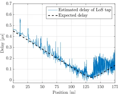
(23) 1. Introduction alternative to OFDM [FAR 11]. These schemes offer some advantages with respect to OFDM. For example, they do not use a CP, hence providing a higher bandwidth efficiency with respect to OFDM; the different users in the uplink do not need to be synchronized, and can yield a better performance in high-speed channels due to a lower inter-carrier interference level.. 1.1. Thesis Overview. Two different parts can be distinguished in this thesis. First, a complete channel characterization is carried out for different scenarios such as HSTs, subways, and vehicle-to-infrastructure (V2I) in roads. Next, the performance of FBMC vs OFDM is experimentally compared in high-speed environments. We have also analyzed the performance of FBMC vs OFDM in the practical use case of a remotely piloted aircraft (RPA). The majority of the work carried out in this thesis has required the design and development of the so-called GTEC 5G simulator, which has been used in conjunction with the GTEC Testbed to perform most of the measurement campaigns and performance evaluations by means of over-the-air transmissions. The present thesis is structured in eight chapters, including this one. A brief summary of each chapter is presented below. Chapter 2 presents in detail a testbed and a modular link-level simulator developed by the GTEC group at the University of A Coruña, known as the GTEC Testbed and GTEC 5G simulator, respectively. This testbed and simulator were developed in order to evaluate the current 4G and future 5G communication techniques, and were used to obtain many of the results presented in the successive chapters. Chapter 3 accounts for the detailed characterization of the downlink between an LTE Evolved Node B (eNodeB) and a HST based on measurements carried out in a commercial HST line. Two links are considered: the one between the eNodeB and the antennas placed outdoors on the train roof, and the direct link between the eNodeB and a receiver inside the train. Such a characterization consists in assessing the path loss, the signal-to-noise ratio (SNR), the K-factor, the power delay profile (PDP), the delay spread, and the Doppler power spectral density (PSD) for different train speeds. Chapter 4 accounts for the characterization of the wireless channel in a modern subway station and its corresponding entrance tunnel, a topic greatly overlooked in the literature. We setup an LTE eNodeB transmitter in the middle of the platform of a modern station in the Madrid Metro, Spain, to cyclically transmit frequency-division duplex (FDD) LTE signals at a carrier frequency of 2.6 GHz with a bandwidth of 10 MHz. Two receivers were used to investigate both the eNodeB-train and the eNodeB-mobile links. The train was moving at a constant speed of 18 km/h from the entrance tunnel until it is completely stopped at the end of the station. Using the multipath components extracted with the space-alternating generalized expectationmaximization (SAGE) algorithm we characterized the wireless channel response for both links based on the following parameters: power delay profile, root mean square delay spread, Doppler 3.
(24) 1. Introduction power spectral density, small-scale fading distribution, and K-factor. Chapter 5 presents the characterization of the wireless channel using LTE signals (employing a time-division duplex mode) in an urban scenario at the University of A Coruña, considering a V2I setup with a car equipped with four receive antennas. We study typical channel parameters such as SNR, PDP, Doppler PSD, and root mean square (RMS) delay profile, together with a diversity gain assessment by means of typical antenna combining methods, namely selection combining (SC), equal gain combining (EGC), and maximum ratio combining (MRC). We show that, in this case, although EGC and MRC offer the best theoretical performance at the expense of a higher complexity, the presence of LoS conditions and a strong SNR difference between the receive antennas yield favorable conditions for simple schemes such as SC. Chapter 6 considers the performance analysis of FBMC. Firstly, the performance of two common prototype filters for FBMC is studied analytically and by means of computer simulations considering standardized channel models for static scenarios. The results are also compared to OFDM. FBMC is next experimentally evaluated through over-the-air transmissions in different environments using the GTEC Testbed, devoting special attention to the performance of FBMC in high-speed scenarios. We also include the results obtained for OFDM signals for comparison purposes. To carry out this analysis, we considered a technique to induce effects caused by highly-time varying channels on multicarrier signals while conducting measurements at low speeds. This technique has been proved to be accurate for the cases of Worldwide Interoperability for Microwave Access (WiMAX) and LTE signals, as well as the waveforms proposed for 5G systems, such as FBMC. Chapter 7 investigates experimentally the feasibility of serving aerial vehicles using LTE network deployments with eNodeB antennas targeting terrestrial coverage. The performed measurement campaign comprised a wide set of results. On the one hand, horizontal flights at eight different height values, ranging from 15 m to 105 m, were performed for two different suburban scenarios with varying obstacle density. On the other hand, vertical flights, from 20 m to 100 m, were also considered for different horizontal distances to the transmitter. In order to study the effect of the transmit antenna radiation pattern, two configurations were considered, one corresponding to an omnidirectional antenna, and the other corresponding to a typical base station antenna. Finally, five different carrier frequency values were considered, from 850 MHz to 3.5 GHz. We transmitted commercial signals (we considered both LTE signals (10 MHz profile) as well as a FBMC-based signals with similar characteristics and bandwidth) and evaluate high-level figures of merit such as (coded and uncoded) bit error rate (BER), error vector magnitude (EVM) and throughput. Finally, Chapter 8 end the thesis by presenting the main conclusions derived from this work and the proposed future work. 4.
(25) 1. Introduction. 1.2. Thesis Methodology and Resources. In this thesis, two different parts can be distinguished. First, we characterized the wireless communication channel for several environments: HSTs, subways, and V2I in roads. Second, the performance of FBMC vs OFDM was experimentally assessed in high-speed environments and in a practical use case of an RPA. For the first part the methodology was the following: • Study the available literature to learn how the wireless communications channels can be analyzed and described based on several parameters. Among others, one of the topics studied was the usage of high resolution parameter estimation (HRPE) algorithms to characterize the channel response. • Perform a characterization of the channel in novel scenarios or with novel characteristics. This characterization was performed using already available measurements, that were carried out in the past in our research group. For the second part where we performed an assessment of the performance of FBMC, the methodology was the following: • Study the available literature to learn the details of FBMC. • Implement a software to evaluate the performance of FBMC and OFDM. This software is the so-called GTEC 5G Simulator which is detailed in Chapter 2. • Perform several measurement campaigns in order to evaluate FBMC and OFDM. First, two measurement campaigns were performed at the University of A Coruña to evaluate the performance of FBMC in high-speed environments. For this, a technique to emulate the effects of high-speed while conducting measurements at low speed was used. Later, a measurement campaign considering an RPA was conducted at the Tonji University, Shanghai. • The performance of FBMC and OFDM was evaluated using the GTEC 5G Simulator. The following resources were employed • Bibliographic resources: scientific publications, information on the web, etc. • The necessary hardware resources for performing the measurements. The specific hardware used for the measurements is explained in the respective chapters of the thesis. • The necessary software for numerical simulation (i.e. MATLAB™), as well as for document edition (LATEX).. 1.3. Co-authored Publications. The work presented in this thesis led to the following co-authored publications included in the list below. 5.
(26) 1. Introduction. Journal Papers 1. Tomás Domínguez-Bolaño, José Rodríguez-Piñeiro, José Antonio García-Naya, Xuefeng Yin, and Luis Castedo. “Measurement-based characterization of train-toinfrastructure 2.6 GHz propagation channel in a modern subway station”. Accepted in IEEE Access, 2018 2. Tomás Domínguez-Bolaño, José Rodríguez-Piñeiro, José Antonio García-Naya, and Luis Castedo. “Experimental characterization and modeling of LTE wireless links in high-speed trains”. Wireless Communications and Mobile Computing, vol. 2017, no. 5079130, 2017, pp. 1–20. DOI : 10.1155/2017/5079130. Conference Papers 1. Tomás Domínguez-Bolaño, José Rodríguez-Piñeiro, José Antonio García-Naya, Xuefeng Yin, and Luis Castedo. “Vehicle-to-infrastructure channel characterization based on LTE measurements”. Proc. of 19th IEEE International Workshop on Signal Processing Advances in Wireless Communications (SPAWC 2018). Kalamata, Greece, 2018 2. Tomás Domínguez-Bolaño, José Rodríguez-Piñeiro, José Antonio García-Naya, and Luis Castedo. “Throughput-based performance evaluation of 5G-candidate waveforms in high speed scenarios”. Proc. of 25th European Signal Processing Conference (EUSIPCO 2017). Kos, Greece, 2017 3. José Rodríguez-Piñeiro, Tomás Domínguez-Bolaño, José Antonio García-Naya, and Luis Castedo Ribas. “Performance assessment of 5G-candidate waveforms in high speed scenarios”. Proc. of 27th IEEE International Symposium on Personal, Indoor and Mobile Radio Communications (PIMRC’16). Valencia, Spain, 2016 4. Tomás Domínguez-Bolaño, José Rodríguez-Piñeiro, José A. García-Naya, and Luis Castedo. “The GTEC 5G link-level simulator”. Proc. of International Workshop on Link- and System-Level Simulations (IWSLS2 2016). Vienna, Austria, 2016, pp. 64–69 5. José Rodríguez-Piñeiro, Martin Lerch, Tomás Domínguez-Bolaño, José Antonio GarcíaNaya, Sebastian Caban, and Luis Castedo. “Experimental assessment of 5G-candidate modulation schemes at extreme speeds”. Proc. of Ninth IEEE Sensor Array and Multichannel Signal Processing Workshop (SAM 2016). Río de Janeiro, Brazil, 2016 6. Tomás Domínguez-Bolaño, José Rodríguez-Piñeiro, José A. García-Naya, and Luis Castedo. “Experimental evaluation of 5G modulation schemes in quasi-static scenarios”. Proc. of 20th International ITG Workshop on Smart Antennas (WSA 2016). Munich, Germany, 2016 7. José Rodríguez-Piñeiro, Tomás Domínguez-Bolaño, Pedro Suárez-Casal, José Antonio García-Naya, and Luis Castedo Ribas. “Affordable evaluation of 5G modulation schemes in high speed train scenarios”. Proc. of ITG Workshop on Smart Antennas 6.
(27) 1. Introduction (WSA 2016). Online access: https://www.vde- verlag.de/proceedings- en/454177072. html. Munich, Germany, 2016. 7.
(28) Chapter II The GTEC Testbed and the GTEC 5G Simulator The recent rapid evolution of wireless communications constitutes a challenge for their versatile and flexible evaluation by means of over-the-air transmissions in different scenarios. In order to evaluate the current fourth generation (4G) and future fifth generation (5G) communication techniques, a testbed and a modular link-level simulator were developed at the GTEC group of the University of A Coruña. The testbed and the simulator were used to obtain the results that will be presented in the successive chapters. In this chapter, the testbed and the simulator are presented in detail. This chapter is mainly based on the following co-authored publication: • Tomás Domínguez-Bolaño, José Rodríguez-Piñeiro, José A. García-Naya, and Luis Castedo. “The GTEC 5G link-level simulator”. Proc. of International Workshop on Link- and System-Level Simulations (IWSLS2 2016). Vienna, Austria, 2016, pp. 64–69 This chapter is structured as follows. Section 2.1 introduces the chapter. Section 2.2 provides an overall description of the GTEC Testbed, including both the hardware and the software elements. We also explain how the GTEC 5G Simulator is integrated into the testbed structure. Section 2.3 describes the simulator architecture in detail, whereas Section 2.4 shows the way to perform simulations, including some exemplary results. Finally, Section 2.5 introduces the typical measurement methodology that we follow to perform evaluations using real world measurements. Section 2.6 concludes the chapter.. 2.1. Introduction. The development of a versatile way of evaluating the performance of a new generations of wireless communications systems by means of over-the-air transmissions under different scenarios is a fundamental issue. In order to allow for the evaluation of the current fourth generation (4G) communication techniques, as well as the new fifth generation (5G) proposals, 8.
(29) 2. The GTEC Testbed and the GTEC 5G Simulator a versatile and flexible testbed and simulator were developed by the GTEC group at the University of A Coruña. The testbed and the simulator are named GTEC Testbed and GTEC 5G Simulator, respectively. The related software and documentation were made publicly available [T EA] under the GPLv3 license [F RE]. The GTEC Testbed allows for performing experimental evaluations, by transmitting signals over the air, as well as receiving the signals for further processing. The GTEC 5G Simulator allows for performing link layer simulations both for orthogonal frequency-division multiplexing (OFDM) and filter bank multicarrier (FBMC) signals (see Chapter 6 for more details on FBMC). It includes fully-functional transmitter and receiver implementations, as well as different channel models and functions for processing the obtained results. Its modular implementation enables us to easily modify or add functionalities by changing or implementing new modules, respectively. Several data structures are defined for parameters and constants, providing a standardized way to configure any module of the simulator. Moreover, the GTEC 5G simulator is fully integrated with the GTEC Testbed, enabling not only to perform simulation-based evaluations, but also to carry out over-theair measurements in different environments. Hence, the GTEC Testbed and the GTEC 5G Simulator are very valuable tools for evaluating wireless communication systems in a versatile and flexible way.. 2.2. The GTEC Testbed. In this section we briefly describe the testbed developed in our research group (GTEC), which was extensively used for experimental evaluations of Worldwide Interoperability for Microwave Access (WiMAX) signals in high speed environments (see [S UÁ +14b; ROD +14; S UÁ +14a]), Long Term Evolution (LTE) signals in subways, railway scenarios and high-speed environments (see Chapters 3 and 4, [ROD +16c; Z HA +16b; F EI +16]). Finally, it has been used also for experimental evaluations of the new waveform proposals for 5G systems (see Chapter 6). The GTEC Testbed allows us to convert previously generated data into electromagnetic waveforms that are transmitted over-the-air, as well as to receive and store the acquired samples for further processing. The testbed consists of several nodes which are evolved versions of the ones described in [ROD +13]. Both the hardware and the software parts of the nodes are described below. Figure 2.1 shows a typical configuration of the testbed, in which one of the nodes is used in transmit-only mode while the other is set up in receive-only mode.. 2.2.1. Hardware. The heart of each node of the GTEC Testbed is an Universal Software Radio Peripheral (USRP™)1 B210 board [R ESa] built from the AD9361 chip [A NA] by Analog Devices, which 1. USRP™ is a registered trademark of National Instruments Corp.. 9.
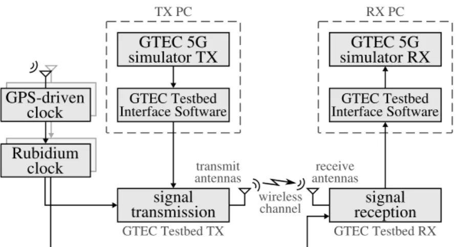
(30) 2. The GTEC Testbed and the GTEC 5G Simulator. GPS-driven clock. TX PC. RX PC. GTEC 5G simulator TX. GTEC 5G simulator RX. GTEC Testbed Interface Software. GTEC Testbed Interface Software. Rubidium clock. transmit antennas. signal transmission. receive antennas. signal reception. wireless channel. GTEC Testbed TX. GTEC Testbed RX. Figure 2.1: GTEC Testbed structure. Exemplary configuration with one transmitter node and one receiver node.. external HPA. Analog Devices AD9361 (70 MHz - 6 GHz). TX DSP 0 TX DSP 1. 2 x DAC 12 bit @ 61.44 MS/s. RX DSP 0 RX DSP 1. 2 x ADC 12 bit @ 61.44 MS/s. clock management. PLL. RF switch network. UHD transport control and time synchronization. VRT-49 2 x 30.72 MS/s. TX LO. fRF. [70 MHz - 6 GHz] [BW: 56 MHz]. RX LO. GTEC Testbed Interface Software SSD. SRS PRS10 rubidium osc. (optional). 1 PPS. Ettus UHD. 10 MHz. 10 MHz aux REF 10 MHz. USB 3.0/2.0 PHY. FPGA Xilinx Spartan 6. 1 PPS. node PC. Ettus USRP B210 (2 × TX/RX). Figure 2.2: Picture of the USRP™ B210 board.. Thunderbolt E-GPS CLK GPS signal. control (RS232). Figure 2.3: Block diagram of a node of the GTEC Testbed.. 10.
(31) 2. The GTEC Testbed and the GTEC 5G Simulator. Figure 2.4: GTEC Testbed node acting as a transmitter. The USRP is connected through its USB 3.0 port to a laptop running a GNU/Linux operating system. On the other side, one of the RF outputs of the USRP is connected to the input port of a high power amplifier.. supports a continuous frequency coverage from 70 MHz to 6 GHz; full-duplex multiple-inputmultiple-output (MIMO) operation with up to two antennas, and a maximum bandwidth of 56 MHz; USB 3.0 connectivity; on-chip 12 bit analog to digital converters (ADCs) and digital to analog converters (DACs) up to 61.44 Msample/s; and configurable transmit and receive gain values. A Rubidium oscillator, optionally driven by a Global Positioning System (GPS)disciplined clock, may also be used at each node to provide very accurate time and frequency synchronization. A picture of the USRP™ B210 board is shown in Fig. 2.2. A block diagram of a node of the GTEC Testbed is shown in Fig. 2.3. In the diagram, the Stanford Research Systems PRS10 (SRS PRS10) and Trimble Thunderbolt E-GPS modules provide the rubidium oscillator and the GPS-disciplined clock, respectively. Both of them are optional. A GPS-disciplined clock available from Ettus can be also used. The advantage of the latter is that it allows for capturing National Marine Electronics Association (NMEA) records to get the position and velocity (among other parameters) of the node.. 2.2.2. Software. USRP™ boards at each node are connected to a laptop equipped with two solid-state drives: one containing a GNU/Linux operating system and the custom-developed measurement software, whereas the other is dedicated to store the transmitted/acquired signals. The laptops are labeled in Fig. 2.1 as “TX PC” (transmitter) and “RX PC” (receiver). There are two main software components used in both nodes, as shown in Fig. 2.1: the GTEC Testbed interface software (GTIS) and the “GTEC 5G Simulator TX/RX”. We show in Fig. 2.4 a picture of a GTEC Testbed node acting as a transmitter, where the USRP™ is connected through its USB 11.
(32) 2. The GTEC Testbed and the GTEC 5G Simulator port to a computer and through one of its radio frequency (RF) output ports to the input port of a high power amplifier. 2.2.2.1. GTEC Testbed Interface Software (GTIS). This software component communicates directly with the USRP™ and is used to set up or change the node configuration, read the signals to be transmitted from disk, and store the acquired samples. We use a custom-developed multi-threaded software implemented in C++ with Boost [DA+] and based on the Ettus USRP™ hardware driver (UHD) [R ESb]. At the receiver, the main thread of the GTIS software pre-processes the samples coming from the USRP™ through the USB 3.0 bus and stores them into a set of circular buffers in the main memory of the host laptop. A secondary thread reads the samples from the buffers and saves them into a dedicated solid-state drive. There is an additional low-priority thread that is responsible for logging important information of the measurements such as the GPS data [ROD 16]. At the transmitter, a single thread is responsible for transmitting the signal samples cyclically. Several wrapper calls were also developed in MATLAB™ to allow for controlling the testbed directly from MATLAB™. 2.2.2.2. GTEC 5G Simulator. This software component is used to generate and process the signals of interest and it is fully integrated with the GTIS part. It could be easily replaced by other software implementations of any desired communication system that meets the constraints of the testbed. For example, the Vienna LTE Simulator [RST16] was integrated with the GTEC Testbed. The GTEC 5G Simulator is described in detail in the following section.. 2.3. The GTEC 5G Simulator. The GTEC 5G Simulator can be used jointly with the GTEC Testbed to perform measurements or in a standalone fashion to perform simulations. In this section we describe its usage in a standalone way.. 2.3.1. Overall Description of the Simulator. The GTEC 5G Simulator was built as a versatile tool to allow us to perform link-level simulations of different kinds of multicarrier modulated signals. Currently, OFDM and FBMC signals are supported. At the transmitter side, signals are generated using a customdeveloped signal generator. For the case of FBMC, two different prototype filters were implemented, namely the one defined by the PHYDYAS project [B EL +10] and the so-called Hermite pulse [HB97]. The latter one is specially suited for transmissions over doubly 12.
(33) 2. The GTEC Testbed and the GTEC 5G Simulator constants generation. parameters. AWGN generation signal generation. signal processing. channel model. GTEC 5G Simulator TX. results. GTEC 5G Simulator RX. Figure 2.5: GTEC 5G Simulator structure for performing simulations.. dispersive channels [HB97]. At the receiver side, a custom-developed receiver is used, which includes algorithms for channel estimation and equalization, as well as time and frequency synchronization. For the case of FBMC signals, channel estimation is not as straightforward as in OFDM, since the lack of orthogonality of FBMC pulses causes interference in the imaginary part of the adjacent symbols. Therefore, channel estimation for FBMC requires using specific algorithms, being the most popular ones those based on the so-called auxiliary pilots. Several auxiliary pilot schemes were implemented on the simulator [JLR03; S TI +10; C UI +15]. The simulator is implemented in a modular way, which enables us to easily modify or add functionalities by changing or implementing new modules, respectively. Several data structures are defined for parameters and constants, providing a standardized way to configure any simulator module.. 2.3.2. Structure of the Simulator. The overall structure of the GTEC 5G Simulator is shown in Fig. 2.5. The GTEC 5G link level simulator can be divided into five basic blocks, namely, “parameters”, “constants generation”, “signal generation”, “channel model,” and “signal processing”. These blocks are described in the following subsections.. 2.3.3. Configuration of Parameters and Constants. To configure the different blocks of our simulator we use a parameters file which is represented in Fig. 2.5 by the “parameters” block. From this file, a MATLAB variable of struct type containing the value of each parameter is generated. This is the first step in setting up the configuration of the different blocks of the system. Among others, the following parameters can be configured: • Number of subcarriers: total number of subcarriers to be considered for the generated signal, including the guard subcarriers. • Number of time symbols: number of symbols, in the time domain, of the generated signal. 13.
(34) 2. The GTEC Testbed and the GTEC 5G Simulator • Subcarriers conforming guard bands: specified as a vector with two elements, indicates the number of guard subcarriers at both sides of the spectrum. • Modulation and demodulation technique to use: OFDM or FBMC. • Modulation dependent setup: specific parameters for the different modulation techniques. For OFDM, the CP length must be specified, whereas for FBMC, the prototype filter to be used must be specified. • Payload setup: different parameters such as the type and modulation order used for the symbols can be configured. Moreover, we can transmit in a single frame several “streams” of data and each one can be configured independently. In the simulator we refer to each stream as a “data block”. For each data block to be inserted in the signal, the following parameters can be configured: – modulation of the symbols: i.e., QAM or PAM. – modulation order of the symbols. – mean power of the symbols: by default, it is 1, but can be changed. – resource elements2 assignment: several resource elements are assigned to the given data block. The modulation, modulation order, and number of resource elements assigned, will determine the maximum number of bits that the data block can carry. – forward error correction (FEC) code: A convolutional code was implemented in the simulator and can be used to correct the transmission errors. Moreover, if the MATLAB LTE toolbox is installed, the LTE turbo code can also be used. The usage of a FEC code can be disabled, which is useful if, for example, we are only interested in results for uncoded bit error rate (BER). – number of uncoded bits in the data block: when a FEC is used, the code rate, or equivalently the number of uncoded bits, must be specified. • Pilot setup: the pilot pattern to be used as well as the modulation and modulation order of the pilot symbols is configured in this point. For the case of FBMC, the usage of auxiliary pilots must be also configured. Currently, the single auxiliary pilot scheme [JLR03; S TI +10], and the so-called coded auxiliary pilot (CAP) scheme [C UI +15] are implemented. • Channel model and noise related parameters: for performing simulations, the channel model to be used and the noise power are configured. • Channel estimation: the channel response is estimated by means of the grid of pilots as configured in the “Pilots setup” point. Zero-forcing (ZF) and minimum mean square error (MMSE) channel estimation algorithms are implemented. • Channel equalization: the received symbols are equalized with the estimated channel response. ZF and MMSE channel equalization algorithms are implemented. 2. The term “resource element” is used here with the same meaning as in the LTE specification, i.e., one symbol in one subcarrier.. 14.
(35) 2. The GTEC Testbed and the GTEC 5G Simulator One block per data stream. Coded bits. Uncoded bits Forward error correction coding. Random data bits generation OFDM. Symbol Matrix. FBMC. Auxiliary pilots addition. Preamble addition Symbol Matrix (incl. preamble). Symbol mapping. Time-frequency grid generation. Signal post-processing Signal in time domain. Pilot symbols. Constellation Symbols. Symbol Matrix (incl. aux. pilots). TX modulator OFDM/FBMC. Constellation Symbols. Signal interpolation for high-speed emulation. Signal in time domain. Signal to be transmitted in time domain. Figure 2.6: GTEC 5G Simulator transmitter structure.. • Synchronization: time and frequency synchronization algorithms were also implemented. For the OFDM case, two synchronization algorithms were implemented, one based on the Schmidl & Cox method [SC97], as well as one custom-made method based on the cyclic prefix (CP). For FBMC, a method based on the one defined in [ZC14] was considered. • High-speed emulation: we implemented in our simulator a method for emulating high-speed receiver velocities designed by our research group and extensively used in previous works (see [ROD +14; ROD +15a; S UÁ +14b; S UÁ +14a; Z HA +16b; ROD +15b; ROD +16b; F EI +16; ROD +16d]). We can configure the high-speed simulation in this point. Another basic block of the system is the “constants generation” block. From the previously established parameters, several constants required by the rest of the blocks are defined. These data include, among others, the following: • Samples of the prototype filter (for the FBMC case). • Channel model related data. • Transmitted pilot symbols. • Different Boolean matrices to access the distinct elements of the time-frequency grids, such as the pilots, the auxiliary pilots (for the FBMC case), or the individual data blocks. • Samples of the preamble used for time and frequency synchronization.. 2.3.4. Transmitter. The transmitter structure is shown in Fig. 2.6. There is no strong dependency between blocks and the configuration of each of them is established by means of the parameters file. This enables for easily modifying or replacing the implementation associated to each block. The first step is to generate the data bits to be transmitted. As stated in Section 2.3.3, our 15.
Figure
+7

Documento similar