© 2014 WIT Press, www.witpress.com
ISSN: 2046-0546 (paper format), ISSN: 2046-0554 (online), http://journals.witpress.com DOI: 10.2495/CMEM-V2-N1-58-70
OPTIMIZED AUTOMATIC SYSTEM TO OBTAIN
ULTRASONIC RADIATION PATTERNS
M. FERNÁNDEZ, C. RODRÍGUEZ, L. ALONSO & J. M. PÉREZ-ORIAElectronics Technology, Systems and Automation Engineering Department, Cantabria University, Spain. ABSTRACT
Due to the need to know and modify the radiation pattern of the ultrasonic sensors, to suit them to a particular application, in this paper is presented an automated measure system to obtain the radia-tion pattern for ultrasonic sensors in air. The system allows to obtain the radiaradia-tion pattern in different conditions, for example for checking the characteristics of the ultrasonic sensors provided by the manufacturer, or for obtaining the modifi cations in the radiation pattern when a mechanical element is coupled to the ultrasonic sensor. In addition, the system has been improved by shortening the mea-surement time and decreasing the volume of data needed to carry out a measure. Furthermore, due to the fact of implementing the system inside a climatic chamber, the system allows to analyze the infl u-ence of environmental factors such as temperature and humidity, plus an evaluation of the degradation behaviour of the ultrasonic sensors in air under conditions of high temperature and humidity. At the end of the paper, two measurements have been done and the results have been compared with the char-acteristics of the radiation pattern provided by the manufacturer. Finally, a robust measurement system is presented, designed to fi nd the modifi cations in the radiation pattern of an ultrasonic sensor when it is coupled to a mechanical element.
Keywords: Automation, measure system, radiation pattern, sensors, signals processing, ultrasounds. 1 INTRODUCTION
Varied and diverse ultrasonic applications can be found in industrial processes, such as measurement of distances and thicknesses [1–3], object recognition [4, 5], quality control, to discover the presence of faults in pieces [6–10], and in applications in medicine [11], such as tumour localization, gynaecological applications, etc.
The principal limitation in the use of ultrasonic sensors is the operation frequency [12, 13]. If the excitation frequency of the ultrasonic sensors is increased, a decrease is produced in their range, but a more directed radiation pattern is achieved. Depending on the application in which the ultrasonic sensors are being used, it may be necessary, for example, to increase the operating distance and direct the beam more. To achieve a greater working range, it is necessary to reduce the frequency. In contrast to obtain a more directed beam, it is necessary to increase the frequency. To obtain both effects simultaneously, without changing the ultra-sonic sensor, there are different techniques to modify the radiation pattern including the use of arrays of sensors or coupling mechanical elements, such us horns, to the ultrasonic sensor. The latter option can be highlighted as it does not increase the hardware complexity of the system and is cheaper and easier to use [14–22]. The geometric and physical characteristics of the coupled element must be carefully chosen to obtain a more suitable radiation pattern. For a specifi c application, it is necessary to obtain a simulated model, and then verify its applicability in an experimental way [23–25].
The ultrasonic radiation pattern gives all the necessary information about the characteris-tics of a sensor, in order to determine whether it can be used in a specifi c application [26, 27].
The radiation pattern of an ultrasonic transducer is generally a data supplied by the manu-facturer. For this reason, the changes produced in it due to the infl uence of different factors (for example temperature, humidity, frequency, size, mechanical elements attached to the own
sensor) can’t be evaluated. The methods to characterize the ultrasonic sensors depend on the specifi c requirements of each problem [28]. In this work, it is presented an automatic system to characterize ultrasonic sensors working in air and derives from the necessity to verify the radiation pattern characteristics given by the manufacturer and, furthermore, it can be used to obtain new characterizations of ultrasonic sensor when it is combined with mechanical elements of different geometries. For this purpose, it is important to design and implement an automatic system that provides a fast, reliable and versatile way to obtain the ultrasonic radiation pattern, both in free radiation case and in the case of a horn coupled to the sensor.
The second section provides a brief description of the independent elements which inte-grate the complete system. The elements used are a positioning system, a data acquisition system and the environmental condition monitoring system. This complete system is placed in a climatic chamber which enables the different environmental conditions to be established.
The third section describes the procedure used to assemble all the parts of the automatic system in a physical way, taking into account all the particularities arising during develop-ment. Moreover, the process to obtain the radiation pattern is described.
The last section of the work describes the behaviour of the automatic system for two different sensors, operating at distinct frequency, with the aim of discovering the radiation pattern. Moreover, this section describes the development of a resource optimization. Finally, a validation of the measurement system developed from the data supplied by the manufacturer is provided.
2 MEASUREMENT SYSTEM DESCRIPTION
Due to the repetitively in the process of characterization or modifi cation of the radiation pat-tern of an ultrasonic sensor, it is necessary to develop an automatic system to carry out this process in a straightforward way. In addition this system must be versatile enough to be able to change the transducer, the mechanical element or the environmental conditions without making a lot of changes. The system presented in this work is made up of several independent subsystems in order to be able to control, to modify and if necessary to adapt the system conditions to the necessities of each application.
2.1 Climatic system
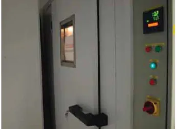
In previous works the infl uence of temperature and humidity on ultrasonic propagation has been studied [29, 30]. It should be highlighted that both humidity and the temperature affect the ultrasonic velocity, although the infl uence of the temperature on the propagation is greater. However, the infl uence of temperature and humidity on the amplitude of the ultrasound is similar. Therefore, it is necessary to obtain the radiation pattern when the temperature and the humidity are known and controllable. Therefore, measurements were made inside a climatic chamber, manufactured by Dycometal, which enables the temperature to be varied from −40°C to 150°C, and the humidity to be varied from 15% to 85% when temperature is between 10°C and 85°C. Figure 1 shows the access to the chamber and the control panel of the climatic chamber. The chamber dimensions are 4.35 m long, 1.50 m wide and 1.90 m high.
Furthermore, in order to visualize the process without changing these climatic conditions, a monitoring system was developed, made up of a camera inside and a monitor outside the chamber. 2.2 Positioning system
To obtain the ultrasonic radiation pattern, it is necessary to sweep the spatial positions to meas-ure the acoustic pressmeas-ure at each point of the workspace. The robot used was a Yamaha SXYBX,
which has three degrees of freedom. The fi rst one allows a linear displacement in the direction of the axis from emitter to receiver. The maximum length of this linear guide is 3 m and it has a precision of 1 mm. The second degree of freedom is the height of the emitter, which has the precision of 1 mm too, although its maximum value is 1.5 m. The third one corresponds to a rotation of the sensor around the vertical axis, which gives the angle between the emission axis and the direction between the emitter and the receiver. Its precision is 0.1°. In Fig. 2, the robot used is shown inside the climatic chamber.
To move the robot it is necessary to use a controller. In this case we chose a controller from the same manufacturer, model RCX40, which enables the control of four degrees of freedom.
Figure 1: Control panel of the climatic chamber.
2.3 Data acquisition system
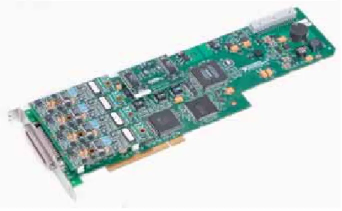
The acquisition system is made up of a PC and a data acquisition card, which is shown in Fig. 3, National Instruments, model NI PCI6110, which has a maximum sampling frequency of 106 samples/second, and it is enough to obtain the echo of ultrasonic sensors in air up to 150 KHz. For the characterization of ultrasonic sensors operating at a higher excitation fre-quency, it would be necessary to use a data acquisition card with a higher sampling velocity or special sampling techniques.
3 MEASUREMENT METHOD DESCRIPTION
Once the hardware system is defi ned, the software part of the system should be developed. In this section, two stages are distinguished. The fi rst stage is the process of acquiring and stor-ing the measurements. Second stage is the processstor-ing stage where the radiation pattern is obtained from the measurements acquired in fi rst stage.
3.1 Measurement system process
From the isolated operation of the systems previously described, it is necessary to assemble the whole system. Figure 4 shows a block diagram in which the connections and relationships between the systems are established.
Two external circuits should be highlighted, the elevator and reducer voltage circuit, which have been added because the data acquisition card and the robot controller work at different voltages.
Before beginning the data capture process, it must be taken into account that the robot requires an origin of the coordinates. This origin allows the robot to adopt the same initial posi-tion, thus avoiding false positions between emitter and receiver. This coordinate origin was chosen at the position in which emitter and receiver were nearest, at the same height and in such a way that the angle between them was 0°. The height was chosen so the emitter was not too close to the fl oor or the ceiling of the climatic chamber, to avoid undesired rebounds. This posi-tion also enabled easy access and the emitter and receiver to be placed at the same height.
The user confi gurable parameters at the beginning of the application are temperature and humidity inside the climatic chamber, the initial and fi nal distance where the user wants to
start the measurement, taking into account the limits established by the robot guide and the frequency necessary to excite the sensor. The measurements will start when the desired tem-perature and humidity have been reached inside the climatic chamber.
To displace the robot to any position, it is necessary that the data acquisition card sends a pulse to the robot controller. Then, the controller, through a program supplied by the manu-facturer, moves the robot to this position. When this movement is fi nished the controller sends a pulse to the data acquisition card confi rming that the robot has moved.
In each position of the robot, the ultrasonic acoustic pressure obtained by the receiver is acquired. In an attempt to reduce errors and undesired noise, in each position, ten ultrasonic echoes are acquired and their average has been saved as the signal to be processed in the next stage.
Figure 5 shows the trajectory followed by the robot. In Step 1, the emitter and receiver are opposite. To choose this point, it was taken into account that the beam pattern is symmetrical
Figure 4: Block diagram of the developed system.
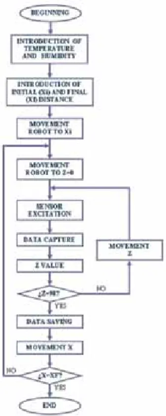
Figure 6: Flowchart of the data capture.
with respect to the axis between emitter and receiver, and so the number of sweep positions adopted by the robot can be reduced by half. Each time the principal program sends a pulse to the controller, it sends an order to the robot to change the degree of freedom corresponding to the angle formed by the emitter and receiver, and so passing the robot into Step 2. When the robot has moved to this new position, the controller sends a pulse to the data acquisition card to verify that it has fi nished its movement. This process is repeated until the angle between emitter and receiver is 90°, as is shown in Step 3. Then, the controller receives a pulse and orders the robot to move to Step 4, when the emitter and receiver are opposite and the distance between them has also decreased.
In Fig. 6 it can be seen the full fl owchart of the data acquisition process. First, the tem-perature and the humidity desired inside the chamber is fi xed by the user. Once these conditions are satisfi ed, the measure will start. After this the user sets the initial and the fi nal distance of the measure. Then the robot goes to the position indicated by the initial distance and with the sensors faced. The emitter is excited by a card pulse, and the echo is saved. Then a movement in the angular position is done. This step is repeated so many times as necessary to achieve 90°. In this moment, the data are saved. Notice that the data contains all the echoes at the same distance but different angular positions. After this, the distance between emitter and receiver is shortened. In the same way as before, this step is repeated until the distance between the sensors reaches the fi nal distance. In this moment the measure fi nishes.
3.2 Process description
The radiation pattern provides the value of acoustic pressure got by the receiver at different points of the space. To obtain this value, the signal has been fi ltered and the Hilbert trans-form is applied to obtain the envelope of the echo. Therefore, the acoustic pressure is the maximum of this envelope at each point. Notice that due to the confi guration, the acoustic pressure searched is the value of the fi rst maximum, which corresponds with the direct dis-tance between the emitter and the receiver. In this way, the possible rebounds with the walls of the chamber are avoided.
Once the fi rst maximum of the signal is obtained at each point depending on the distance and the angle between the emitter and the receiver, the radiation pattern can be plotted in polar or in Cartesian coordinates, changing coordinates via software.
4 PERFORMANCE OF MEASUREMENTS
To obtain the characterization of a radiation pattern of a sensor with the system developed, two hexamite sensors (model HX25TR) were used for measurement, one operating as emitter and the other as receiver, both at a frequency of 25 KHz. These sensors can achieve long distances using suitable electronics. For the distances inside the climatic chamber, there is no necessity to use any additional electronics.
It must be taken into account that the movement of the robot must be synchronized with the excitation of the emitter and the signal obtained by the receiver, and overlap must be avoided. Therefore, the data acquisition by the ultrasonic system is carried out between the pulse that the controller sends to the data acquisition card indicating that the movement has fi nished and the pulse sent by the data acquisition card to the robot controller to order a new movement.
In these conditions a measurement was made, in which the angle between emitter and receiver varied from 0° to 90°, due to the symmetry of the pattern, with a step of 1°. The distance between them was varied from 3.18 m to 0.18 m with a step of 0.01 m. The initial distance of 0.18 m between emitter and receiver will enable mechanical elements to be cou-pled to the sensor in next works, with the objective of modifying and obtaining the new radiation diagram.
Using the Fast Fourier Transform (FFT) the optimal excitation frequency of this sensor and the bandwidth are obtained. The optimal excitation frequency is the frequency that produces the maximum value in the FFT calculated. The bandwidth is obtained from the value of the optimal excitation frequency, and then the frequencies in which the signal has decreased 6dB are calculated. Figure 7 shows the FFT at a distance of 52 cm. With the average of all the measurements, we obtain an optimal excitation frequency of 25.68 KHz and a bandwidth of 1.38 KHz.
Figure 8 shows the radiation pattern of an ultrasonic sensor working at a frequency of 25 KHz in Cartesian coordinates, at a temperature of 20°C and humidity of 80%.
To obtain the width of the principal beam, it is necessary to obtain the maximum of the signal at a specifi c distance, and then the angle is calculated when the amplitude of the signal has decreased 3dB. In our case, the angle obtained was 23.65°. Figure 9 shows the width of the beam at a distance of 52 cm.
The program enables the radiation pattern to be obtained in polar coordinates, as well. Figure 10 shows the radiation pattern of the same sensor, but in polar coordinates.
Due to the large number of points in the workspace, the duration of the full process is very long, approximately 27 hours. With the aim of optimizing this time, a comparison is made between two echoes, at the position where the sensors are opposite and their separation has decreased by 1 cm. For this comparison, it is necessary to carry out real-time pre-processing of both echoes to obtain their maximum value. If the maximum value of the second echo, for the position in which the sensors are 1 cm nearer, does not surpass the maximum value of the previous echo by 10%, the robot moves the sensors 1 cm closer, i.e. the distance becomes 1 cm shorter. This step is repeated successively until the difference between the fi rst and the second echoes is at least 10%. When this is achieved, the acquisition is carried out at this distance and the previously described angular sweep before is carried out from 0° to 90°. Notice that this also produces a reduction in the data volume.
Figure 7: Fast Fourier Transform at 52 cm.
Figure 8: Ultrasonic radiation pattern in Cartesian coordinates for a sensor operating at 25 KHz.
The measurement process also includes an optimization of the dimension of the data saved. To perform this optimization, two consecutive echoes are taken at the same distance, but with a difference in their angular position of 1°. In the same way as was done for the temporal optimization, it is necessary to carry out real-time pre-processing in order to fi nd out whether the maximum value of the second echo captured is 10% smaller than the fi rst echo. If this condition is satisfi ed, the robot is moved without saving data. If not, the echo is saved.
To verify that the system functions correctly both in terms of its temporal optimization and the optimization of the quantity of data saved, a new radiation pattern measurement is
Figure 9: Beam width.
made with two Hexamite sensors working at 40 KHz. The measurement time is noticeably reduced, to about 3 hours, providing a time reduction of 90%. The data volume also decreased to 30% of the initial data volume. In Fig. 11, we can see the FFT of the signal received at 80 cm, where the optimal excitation frequency is 39.62 KHz and the bandwidth is 2.02 KHz.
Figure 12, we can see the radiation pattern of the sensor working at 40 KHz in polar coor-dinates. It can be observed that the beam width has decreased, demonstrating that on increasing the excitation frequency, the directivity of the ultrasonic beam increases.
Figure 11: Fast Fourier Transform at 80 cm.
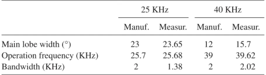
To validate the intelligent automatic system, the data provided by the manufacturer were compared with the data obtained in the experimental measurements in terms of the main beam width, the optimal excitation frequency and the bandwidth. The results obtained are shown in Table 1.
5 CONCLUSIONS
This work describes the development of an automatic system for characterizing ultrasonic sensors and to obtain the radiation pattern, through assembly and coordination of different types of subsystems, namely, positioning system, climatic system and data acquisition system.
This automation originates from the need to obtain the ultrasonic radiation pattern for different sensors and/or in different conditions. Thanks to this automation and the versatility of the system, we can easily fi nd the modifi cations that the radiation patterns undergo when the sensor is changed. In the development of the system, the method for changing the sensor without affecting any part of the system has been considered thoroughly, and for this reason, the connections are made in a zone outside the climatic chamber, which is prepared specifi -cally for this purpose. A system optimization has also been introduced to noticeably reduce the time taken and the volume of data.
In the fi nal part of the work, an experimental validation of the measurement system has been carried out, using two sensors of Hexamite and the characteristics of the radiation pat-tern given by the manufacturer. The similarity in the results allows to validate the measurement system implemented and developed to characterize ultrasonic sensors working in air.
This system enables the modifi cations of the radiation characteristics to be precisely obtained when a mechanical element is coupled to the sensor, in order to provide the horn characteristics to obtain the most appropriate radiation pattern for the application.
Moreover, the ultrasonic sensor behaviour with different environmental conditions and operational limits can also be studied.
ACKNOWLEDGMENTS
This work was carried out with the aid of the Spanish Ministry of Science and Innovation within the project DPI 2007-64295.
REFERENCES
[1] Carullo, A. & Parvis, M., An ultrasonic sensor for distance measurement in automo-tive applications. IEEE Sensors Journal, 1(2), pp. 143–147, 2001. doi: http://dx.doi. org/10.1109/JSEN.2001.936931
Table 1: The comparison between the data provided by the manufacturer and the data obtained in the measurements.
25 KHz 40 KHz
Manuf. Measur. Manuf. Measur.
Main lobe width (°) 23 23.65 12 15.7
Operation frequency (KHz) 25.7 25.68 39 39.62
[2] Egaña, A., Seco, F. & Ceres, R., Processing of ultrasonic echo envelopes for object location with nearby receivers. IEEE Transactions on Instrumentation and Measure-ment, 57(12), pp. 2751–2755, 2008. doi: http://dx.doi.org/10.1109/TIM.2008.926408
[3] Abellanas, A., Frizera, A., Ceres, R., Raya, R. & Calderón, L., Ultrasonic time of fl ight estimation in assistive mobility: improvement of the model-echo fi tting. Proceedings Eurosensors XXII, Dresden, Germany, pp. 464–467, 2008.
[4] Pérez-Oria, J. & Groba, A.M., Object recognition using ultrasonic sensors in robotic applications. XIX Annual Conference of the IEEE Industrial Electronics Society, IECON93, Hawaii, USA, 1993.
[5] Llata, J.R., Sarabia, E.G. & Oria, J.P., Pattern recognition with ultrasonic sensors: a neural network evaluation. Sensor Review, 21(1), pp. 45–57, 2001. doi: http://dx.doi. org/10.1108/02602280110365653
[6] Rodríguez Martínez, J.A., Vitola Oyaga, J. & Sandoval Cantor, S.P., Diseño y construc-ción de un sistema para examen no destructivo de fallas y defectos en metales utilizando señales ultrasónicas. Revista Eia, ISSN: 1794-1237.
[7] Arce, J., Llata, J.R., Sarabia, E.G. & Oria, J.P., Automatic fault detection using ultra-sonic techniques: expert system vs signal processing. IEEE International Symposium on Industrial Electronics, Pretoria, South Africa, 1998.
[8] Pérez-Oria, J., Rentería, L.A., Rodríguez, C., Fernández, M. & Llata, J.R., Ultrasonic identifi cation techniques of defective pieces in hostile production environments. Forum Acusticum 2002, Sevilla, Spain, 2002.
[9] Rodríguez, C., Fernández, M., Alonso, L., Pérez-Oria, J., Ibarra, M., Arce, J. & Gutierrez, J., Automatización de un sistema de detección de defectos en piezas metáli-cas. XXXI Jornadas de Automática, JA2010, Jaen, España, 2010.
[10] Ramirez Gomez, F., Fernández Soler, M.A., Alonso Roldán, A., Delojo Morcillo, G., Valdecantos Martinez, C. & de los Ríos Rubalcaba, J.M., Métodos de ensayos no destructivos (Tomo I), Inta: Madrid, 1996.
[11] Álvarez Fernández, J.A. & Pérez Quintero, R., Ultrasonidos y «vida encefálica». Medicina Intensiva, 30(3), pp. 113–115, 2006. doi: http://dx.doi.org/10.1016/S0210-5691(06)74484-9
[12] Kinsler, L.E., Frey, A.R., Coppens, A.B. & Sanders, J.V., Fundamentals of Acoustics, Wiley, cop.: New York, 1982.
[13] Eisner, E., Complete solutions of Webster Horn equation. Journal of the Acoustical Society of America, 41, p. 1126, 1967.
[14] Alonso, L., Rodríguez, C., Fernández, M., Robla, S., Sarabia, E.G. & Pérez-Oria, J., Conformación mediante bocinas de lóbulos de radiación de sensores ultrasónicos. XXV Jornadas de Automática, JA2004, Ciudad Real (España), 2004.
[15] Alonso, L., Pérez-Oria, J.M., Fernández, M., Rodríguez, C. & Robla, S., Qualitative analysis of the infl uence of horns on ultrasonic lobes. Proceedings of Control and Applications, IASTED2005, Cancún (México), 2005.
[16] Udawalpola, R. & Berggren, M., Optimization of an acoustic horn with respect to effi ciency and directivity. International Journal for Numerical Methods in Engineering,
73(11), pp. 1571–1606, 2007. doi: http://dx.doi.org/10.1002/nme.2132
[17] Udawalpola, R., Wadbro, E. & Berggren, M., Optimization of a variable mouth acous-tic horn. International Journal for Numerical Methods in Engineering, 85, pp. 591–606, 2011. doi: http://dx.doi.org/10.1002/nme.2982
[18] Bright, A., Analysis of a Folded Horn. Audio Engineering Society Convention Paper, 2003.
[19] Webster, A.G., Acoustical impedance and the theory of horns and of the phonograph. Proceedings of the National Academy of Sciences of the United States of America, pp. 275–282, 1919. Reprinted in J. Audio Engineering Soc., 25, pp. 24–28, 1977. [20] Bängtsson, E., Noreland, D. & Berggren, M., Shape optimization of an acoustic horn.
Computer Methods in Applied Mechanics and Engineering, 192(11–12), pp. 1533–1571, 2003. doi: http://dx.doi.org/10.1016/S0045-7825(02)00656-4
[21] Wadbro, E. & Berggren, M., Topology optimization of an acoustic horn computer methods. Applied Mechanics and Engineering, 196, pp. 420–436, 2006. doi: http:// dx.doi.org/10.1016/j.cma.2006.05.005
[22] Martin, P.A., The horn-feed problem: sound waves in a tube joined to a cone, and related problems. Journal of Engineering Mathematics, 71(3), pp. 291–304, 2011. doi: http:// dx.doi.org/10.1007/s10665-011-9454-8
[23] Fernández, M., Rodríguez, C., Alonso, L. & Pérez-Oria, J., Simulación del diagrama de radiación ultrasónico modifi cado por bocinas y validación experimental del modelo de elementos fi nitos. XXVII Jornadas de Automática, JA2006, Almería (España), 2006. [24] Fernández, M., Rodríguez, C., Pérez-Oria, J.M., Ibarra, M. & Alonso, L., Ultrasonic
sensors with mechanical couplers: simulation and validation. Proceedings of the 10th International Conference on Computational and Mathematical Methods in Science and Engineering, CMMSE2010, Almeria (España), 2010.
[25] Noreland, D., Udawalpola, R., Seoane, P., Wadbro, E. & Berggren, M., An effi cient loudspeaker horn designed by numerical optimization: an experimental study. Technical Report, Umeå University (Sweden), 2010.
[26] Leo, L. & Beranek, A., Acoustical Measurements, Editorial E. H. S.: Buenos Aires, 1961.
[27] Murata Manufacturing Co., L. Ultrasonic sensors. Application Manual, available at http://www.murata.com/products/catalog/pdf/s15e.pdf
[28] Gutiérrez, M.I., Leija, L. & Vera, A., Determinación y Evaluación del Campo Acústico de Transductores Ultrasónicos para Fisioterapia. Simposio de Metrología, Santiago de Querétaro, México, 2008.
[29] Alonso Rentería, L., Rodríguez, C., Fernández, M., Robla, S. & Pérez-Oria, J.M., Compensation of environmental parameters for driving-aid ultrasonic systems in foggy conditions. Proceedings of World Automation Congress, WAC2004, Sevilla (España), 2004.
[30] Cacicedo, E., Freire, T., Martín, J.M., Calderon, L. & Ceres, R., Ultrasonics- temperature shapes the envelope. Sensor Review, 14(4), pp. 19–23, 1994. doi: http:// dx.doi.org/10.1108/EUM0000000004234