Escuela Técnica Superior de Ingeniería de Telecomunicación
TESIS DOCTORAL
Analysis and Design of Enhanced Planar Devices Using
Multiconductor Transmission Lines With
Interconnected Alternate Lines
Autor:
JUAN JOSÉ SÁNCHEZ MARTÍNEZ
Director:
ENRIQUE MÁRQUEZ SEGURA
EDITA: Publicaciones y Divulgación Científica. Universidad de Málaga
Esta obra está sujeta a una licencia Creative Commons:
Reconocimiento - No comercial - SinObraDerivada (cc-by-nc-nd): Http://creativecommons.org/licences/by-nc-nd/3.0/es
Cualquier parte de esta obra se puede reproducir sin autorización pero con el reconocimiento y atribución de los autores.
No se puede hacer uso comercial de la obra y no se puede alterar, transformar o hacer obras derivadas.
Abstract ix
Acknowledgments xi
Acronyms xiii
1. Introduction 1
1.1. Contextual Framework . . . 1
1.2. Motivation and Objectives . . . 3
1.3. Thesis Outline . . . 4
1.4. Publications . . . 5
References . . . 7
2. Phase Shifters 11 2.1. Introduction . . . 11
2.2. Analysis and Design Procedure . . . 13
2.3. Open- and Short-Circuited Wire-Bonded MTL . . . 19
2.4. Experimental Results . . . 21
2.5. Conclusion . . . 22
References . . . 23
3. Baluns 25 3.1. Introduction . . . 25
3.2. Analysis and Design Procedure . . . 27
3.2.1. Balun Architecture . . . 27
3.2.2. Theoretical Study . . . 27
3.2.3. Bandwidth Considerations . . . 32
3.3. Reconfigurable Measurement Test Set for Differential Circuit Characterization 40
3.3.1. Introduction . . . 40
3.3.2. Measurement Technique . . . 40
3.3.3. Implementation and Characterization . . . 41
3.3.4. Measurement Verification . . . 45
3.4. Conclusion . . . 46
References . . . 48
4. MTL-Based Stubs 51 4.1. Introduction . . . 51
4.2. Theoretical Analysis . . . 53
4.2.1. One-Port Wire-Bonded MTL Equivalent to Open- or Short-Circuited Shunt Stubs . . . 55
4.2.2. One-Port Wire-Bonded MTL Equivalent to a Pair of Parallel or Series Short- and Open-Circuited Shunt Stubs . . . 58
4.3. Design of an Artificial TL with LH Pass-Band Behaviour and Improved Out-of-Band Rejection . . . 61
4.4. Experimental Validation . . . 65
4.5. Conclusion . . . 68
References . . . 69
5. Ultra-Wideband Differential Bandpass Filters 71 5.1. Introduction . . . 71
5.2. Analysis and Design Procedure . . . 72
5.2.1. Single-Section Differential Filter . . . 73
5.2.2. Double-Section Differential Filter . . . 79
5.3. Experimental Validation . . . 83
5.4. Conclusion . . . 85
References . . . 86
6. Selective Wideband Quasi-Elliptic Bandpass Filters 89 6.1. Introduction . . . 89
6.2. Analysis and Design Procedure . . . 91
6.2.1. Single- and Double-Section Open-Circuited Wire-Bonded MTLs . . . 92
6.2.2. Shunt Short-Circuited Wire-Bonded MTL . . . 97
6.2.3. Asymmetrical Topology . . . 99
6.2.4. Symmetrical Topology . . . 102
6.2.5. Calculation of Even- and Odd-Mode Impedances . . . 110
6.3. Experimental Validation . . . 111
6.4. Conclusion . . . 115
7. Conclusions 119
7.1. Summary and Thesis Achievements . . . 119
7.2. Future Work . . . 121
A. Characterization of a MTL as a Pair of Coupled Lines 123 References . . . 127
B. Solution of Cubic Equations 129 References . . . 130
C. Summary in Spanish 131 C.1. Introducción . . . 131
C.1.1. Marco Contextual . . . 131
C.1.2. Motivación y Objetivos . . . 134
C.1.3. Estructura de la Tesis . . . 134
C.1.4. Publicaciones . . . 136
C.2. Desfasadores de Tipo Reflexivo . . . 138
C.2.1. Analisis y Principio de Funcionamiento . . . 138
C.2.2. Modelos Equivalentes para MTL en Abierto o en Cortocircuito . . . . 141
C.2.3. Validación Experimental . . . 141
C.3. Baluns: Conversión del Modo Común al Modo Diferencial . . . 141
C.3.1. Análisis y Caracterización . . . 141
C.3.2. Sistema de Medida Reconfigurable Para Dispositivos Diferenciales . . 144
C.4. Dispositivos de un Puerto . . . 145
C.4.1. Análisis y Caracterización . . . 145
C.5. Filtros Diferenciales Paso Banda de Banda Ancha . . . 148
C.5.1. Análisis y Caracterización . . . 148
C.6. Filtros Paso Banda Cuasi-Elípticos . . . 150
C.6.1. Análisis y Caracterización . . . 150
C.7. Conclusiones . . . 153
First of all, I would like to express my gratitude to my supervisor Enrique Márquez Segura for giving me the opportunity to work during these last four years on different interesting topics. Thanks to him for his encouragement and discussions during the research process.
I would also like to thank Carlos Camacho Peñalosa and Teresa Martín Gue-rrero for their help and support. To my fellow lab-mates Yak and Elena for the good moments that we have spent together. Thanks to all of them for their com-pany along the way.
I also want to thank Prof. Stepan Lucyszyn for allowing me to be part of the Optical and Semiconductor Devices group at Imperial College London during three months. I am gratefully with his warm welcome and advices during my stay.
In addition, I would like to thank Luis Díez, José Antonio Cortés and Francisco Javier Cañete. They are outstanding researchers in power line communications (PLC) and it was a pleasure to work with them before starting this PhD.
Last but not least, I would like to thank my family. Really, they deserve all my gratefulness because without their love and patient, this thesis would have not been possible.
ADM Amplitude Difference Measure.
BMC Broadband Multilayer Capacitor.
CMRR Common-Mode-Rejection Ratio.
CRLH Composite Right/Left Handed.
DMRR Differential-Mode-Rejection Ratio.
DUT Device Under Test.
FDM Frequency Difference Measure.
FSV Feature Selective Validation.
GDM Global Difference Measure.
LH Left-Handed.
MEMS Micro-Electro-Mechanical Systems.
MMR Multiple-Mode Resonators.
MoM Method of Moments.
MTL Multiconductor Transmission Line.
RF Radio Frequency.
RH Right-Handed.
TEM Transverse Electro-Magnetic. TL Transmission Line.
TRL Thru-Reflect-Line.
UWB Ultra-Wide-Band.
Introduction
T
hepresent chapter will attempt to summarize the content of this dissertation. Section1.1begins with a description of the contextual framework upon which this work is built. Thereby, Section1.2presents the motivations and goals of this project. The aims and organi-zation of this thesis with a brief outline of the main contents of each chapter are presented in Section1.3. Finally, the publications that have been derived from this work are summarized in1.4.
1.1. Contextual Framework
Coupled-line structures play an important role in many distributed RF and microwave circuits [1–7]. As circuit elements, coupled lines have been widely employed in baluns, directional couplers, phase shifters, impedance transformers, dc blocks, interdigital capacitors, filters, and spiral inductors. Planar edge-coupled lines with lines in the same plane are usually employed in microstrip technology. Nevertheless, they are not suitable for tight coupling values because they require a very small spacing between lines. Thus, edge-coupled structures are intended for coupling factors to about 10 or 8 dB, while for tighter couplings of the order of 2 to 3 dB, broadside-coupled lines are used [2]. This aspect is very important because in many practical circuits tight couplings of around 3 dB are required. Therefore, other alternatives that include multilayer configurations, Lange couplers or tandem couplers are employed [2].
applications of the parallel coupled transmission lines. In addition, there are different types of coupled filters, but the most common are paralled-coupled-line [11], interdigital [12, 15], combline [19] and hairpin line [20,21] filters.
Parallel coupled lines configuration is attractive for realizing microstrip bandpass filters for broadband applications where the selectivity is not severe. Approximate design and syn-thesis formulas have been well documented for determining the dimensions of each stage for an all-pole bandpass filter [1]. The design of parallel-coupled line filters was introduced in [11], which have been refined or modified for specific conditions or applications [2]. To derive these formulas, each coupled stage is modeled as a two-port network of two quarter-wave transmission line sections with an impedance inverter in between. However, this approxima-tion has only a good accuracy when the filter has a relatively small bandwidth around the center frequency. Therefore, filters designed using immittance inverter theory are best applied to narrow or moderate bandwidth filters.
In recent years, since conventional filter theory is based on the narrow-band assumption, several techniques in the design of ultra-wideband (UWB) filters have been proposed [22]. One of the proposed topologies is based on multiple-mode resonators (MMR) with stepped-impedance or stub-loaded configuration [23]. Most of these MMR-based filters combine in-put/output parallel coupled lines with different types of MMR structures. The formation of the desired ultra-wide passband is dependent on the coupling strength of the two input/output structures.
Reflection type phase shifters based on coupled structures consist of a 3-dB directional coupler and two identical reflection terminations. When equal power split and phase quadra-ture are maintained between the coupled and direct ports, perfect input and output matching with zero insertion loss is achieved. The relative phase shift is controlled by the reflection coefficient of the reflection terminations, and the bandwidth of operation is determined by both the coupler and the reactive loads [5]. Consequently, for this application it is necessary to use tight couplers.
Coupled-line structures are also used to synthesize baluns. A balun is a transformer used to convert an unbalanced input signal into a balanced differential output one. Different baluns configurations have been reported by using sections of single or coupled transmission lines. Planar baluns based on coupled lines can be divided into two groups, quarter-wave coupled line baluns and Marchand coupled-line baluns [2]. Marchand baluns are probably the most popular [24]. Marchand balun consists of two sections of quarter-wavelength coupled lines and in order to broaden the bandwidth a strong coupling level for the two coupled-line sections is required. However, the main limitation is its poor balanced output ports matching and isolation [25].
by connecting several lines in an interdigital manner. One implementation of this idea is the Lange coupler [26], an interdigitated microstrip coupler that consists of three or more lines with alternate lines tied together. Other alternatives to increase the coupling are the use of multi-layer broadside coupled-structures, which is difficult to build on ceramic or mono-lithic substrates, as well as tandem sections or branch-line couplers, which have a narrower bandwidth.
The Lange coupler is a multiconductor directional coupler in which the mutual capacitance between the lines can be increased without the need for a very small space between them. By increasing the mutual capacitance the coupling between lines increases [2]. The design equations of a k-line interdigital coupler in terms of the even- and odd-mode impedances of a pair of coupled lines are given in [27,28].
More recently, multiconductor coupled lines with interconnected alternate lines have been used to synthesize enhanced interdigital capacitors. The resulting device is the so-called wire-bonded interdigital capacitor, which exhibits a greater bandwidth since undesired resonances at higher frequencies are eliminated [29]. In an interdigitated directional coupler the electrical length of the transmission lines is 90o at the center frequency of operation. On the contrary,
the lines in the interdigital capacitor are always shorter than a quarter of wavelength in order to show a capacitive behaviour. An analytical model (valid for an even number of conductors) of this new circuit was published in [30] while an exact analysis (valid for any number of lines) was derived in [31]. Therefore, it can be noted that multiconductor coupled-line structures can be very attractive in order to design new devices or improving the performance of existing circuits. These structures provide greater coupling factors and can be analytically dealt with.
1.2. Motivation and Objectives
As described in previous section, coupled-line structures consisting of two single lines have been extensively used. Nevertheless, given that there is a direct relation between the achiev-able operational bandwidth and the coupling factor, the use of multiconductor transmission lines (MTL) appear ideal for wideband devices. Besides, thanks to the modeling and charac-terization of multiple coupled lines, it will be possible to obtain analytical design equations [27,30,31].
1.3. Thesis Outline
This work, divided into six chapters, deals with the analysis and design of specific enhanced components such as phase shifters, baluns and filters.
In Chapter 2, multiconductor transmission lines are investigated to synthesize minia-turized and broadband reflection-type phase shifters. The analysis of wire-bonded MTLs is accomplished and generalized in order to extend the traditional theory where 3-dB quarter-wavelength directional couplers are usually employed. In this chapter some basic circuit pa-rameters are established and two general equivalent circuits are obtained for two particular arrangements, when both coupled and direct ports are open or short-circuited. These simple equivalent circuits and the theory developed in this chapter will be used through the rest of the work.
InChapter 3, a novel generalized design procedure of broadband planar baluns with two MTLs to convert single-ended input signals into differential signals is presented. Closed-form design equations to have perfect amplitude and phase balance are obtained. By using this balun, a new reconfigurable test set for the characterization of differential devices is designed and fabricated.
In Chapter 4, the analysis of MTL components when used as shunt stubs is presented. A general study is accomplished and some physical insights into the frequency behaviour of the different one-port MTL structures are provided. To validate the design equations, two artificial transmission lines with left-handed bandpass response and improved out-of-band rejection are synthesized.
Once the MTL elements have been thoroughly analyzed as two-port and one-port circuits in Chapters 2, 3, and 4, the next two Chapters use this theory to design bandpass filters. A systematic design procedure of ultra-wideband differential bandpass filters is presented in Chapter 5. Single- and double-section filters are considered to have a Butterworth or Chebyshev frequency response and some prototypes are manufactured to assess the developed theory.
Chapter 6 focuses on the study of high-selectivity filters with a quasi-elliptic frequency response. Two asymmetric and symmetric configurations are proposed and analyzed. These new topologies are suitable for implementing three- and/or five-pole bandpass filters. The experimental results demonstrate that both structures are suitable to synthesize bandpass filter with sharp cut-off slopes.
1.4. Publications
Phase Shifter
1
2
3
4
k-3
k-2
k-1
k 1
...
2 3
4 Phase Shifter
Phase Shifter
Phase Shifter
Phase Shifter
MTL
Chapter 2Chapter 3
Chapter 4
Chapter 5
Chapter 6
Phase Shifter Balun / Reconfigurable
Test Set
Stubs
Differential Bandpass
Filters
Quasi-Elliptic Bandpass
Filters [32][33]
[34][35][36][37]
[38][39][40][41][42]
[43][44]
[45][46][47]
Figure 1.1.: Thesis structure and contributions.
The following publications have been derived from the work developed in this thesis (see Fig.1.1).
Journals
• [38] J. J. Sánchez-Martínez, E. Márquez-Segura, P. Otero, and C. Camacho-Peñalosa "Artificial Transmission Line with Left/Right-Handed Behavior Based on Wire Bonded Interdigital Capacitors," Progr. Electromagn. Res. B, vol. 11, pp. 245-264, 2009.
• [32] J. J. Sánchez-Martínez and E. Márquez-Segura, “Analytical Study of Wide-band Bandpass Filters Based on Wire-Bonded Multiconductor Transmission Lines With LH Behaviour,”Progr. Electromagn. Res. Lett., vol. 31, pp. 1-13, 2012.
• [39] J. J. Sánchez-Martínez and E. Márquez-Segura, “Comments on ’Wideband Coupled-Line Microstrip Filters With High-Impedance Short-Circuited Stubs’,” IEEE Microw. Wireless Compon. Lett., vol. 22, no. 9, p. 492, Sep. 2012.
Progr. Electromagn. Res., vol. 134, pp. 169-187, 2013.
• [40] J. J. Sánchez-Martínez, E. Márquez-Segura, and C. Camacho-Peñalosa, “Analysis of wire-bonded multiconductor transmission-line-based stubs,” IEEE Trans. Microw. Theory Tech., vol. 61, no. 4, pp. 1467-1476, Apr. 2013.
• [33] J. J. Sánchez-Martínez and E. Márquez-Segura, “Analysis of wire-bonded multicon-ductor transmission line-based phase-shifting sections,” J. Electromagn. Waves Appl.,
vol. 27, no. 16, pp. 1997-2009, Sep. 2013.
• [45] J. J. Sánchez-Martínez, E. Márquez-Segura and S. Lucyszyn, “Design of Com-pact Wideband Bandpass Filters Based on Multiconductor Transmission Lines With Interconnected Alternate Lines,”IEEE Microw. Wireless Compon. Lett., vol. 24, no. 7,
pp. 454-456, Jul. 2014.
• [43] J. J. Sánchez-Martínez and E. Márquez-Segura, “Analytical Design of Wire-Bonded Multiconductor Transmission Line-Based Ultra-Wideband Differential Bandpass Fil-ters,” Accepted to be published inIEEE Trans. Microw. Theory Tech., Jun. 2014. • [46] J. J. Sánchez-Martínez, E. Márquez-Segura and S. Lucyszyn, “Synthesis and
De-sign of High-Selectivity Wideband Quasi-elliptic Bandpass Filters Using Multiconductor Transmission Lines,” Submitted toIEEE Trans. Microw. Theory Tech., Apr. 2014.
International Conferences
• [41] J. J. Sánchez-Martínez, E. Márquez-Segura, and C. Camacho-Peñalosa, "Analysis of Composite Left/Right-Handed Transmission Line Using Shunt Wire Bonded Inter-digital Capacitors," in 4th Young Scientist Meeting on Metamaterials (YSMM), Feb. 2011, ISBN: 978-84-693-9971-2.
• [42] J. J. Sánchez-Martínez, E. Márquez-Segura, and C. Camacho-Peñalosa,“Synthesis of CRLH-TLs Based on a Shunt Coupled-line Section,” in 42nd European Microwave Conference (EuMC), Oct. 2012, pp. 675-678.
• [35] S. Cobos-Bandera, J. J. Sánchez-Martínez, and E. Márquez-Segura, “Mems-based reconfigurable test-set for differential and common mode measurement using a two-port network analyzer,” in 42nd European Microwave Conference (EuMC), Oct. 2012.
Spanish National Conferences
• [37] J. J. Sánchez-Martínez and E. Márquez-Segura, “Análisis de un Balun Basado en Líneas de Transmisión Multiconductoras,” in XXVII Simposium Nacional de la Unión Científica Internacional de Radio (URSI), Sep. 2012, ISBN: 978-84-695-4326-9.
• [47] J. J. Sánchez-Martínez and E. Márquez-Segura, “Análisis y Diseño de Filtros Paso Banda con Alta Selectividad Espectral Basados en Líneas de Transmisión Multiconduc-toras,” in XXVIII Simposium Nacional de la Unión Científica Internacional de Radio (URSI), Sep. 2013, ISBN: 978-84-941537-1-6.
• [44] J. J. Sánchez-Martínez and E. Márquez-Segura, “Análisis y Diseño de Filtros Difer-enciales Basados en Líneas Acopladas,” Accepted in XXIX Simposium Nacional de la Unión Científica Internacional de Radio (URSI), Sep. 2014.
References
[1] G. L. Mattahei, L. Young, and E. M. T. Jones, Microwave Filters, Impedance-Matching Networks, and Coupling Structures, M. A. House, Ed. Norwood, 1985.
[2] R. Mongia, I. Bahl, and P. Bhartia,RF and Microwave Coupled-Line Circuits. Norwood, MA: Artech House, 1999.
[3] J. A. B. Faria, Multiconductor Transmission-line Structures: Modal Analysis Techniques. New York: Wiley, 1993.
[4] I. C. Hunter,Theory and Design of Microwave Filters, Stevenage, Ed. U.K.: IEE Press, 2001.
[5] I. D. Robertson and S. Lucyszyn,RFIC and MMIC Design and Technology. London, UK: IEE Press, 2001.
[6] J.-S. Hong and M. J. Lancaster,Microstrip Filters for RF/Microwave Applications, K. Chang, Ed. Wiley-Interscience, 2001.
[7] C. Caloz and I. Itoh, Electromagnetic Metamaterials: Transmission Line Theory and Microwave Appli-cations. Wiley-Interscience, 2006.
[8] S. Cohn and R. Levy, “History of Microwave Passive Components with Particular Attention to Directional Couplers,”IEEE Trans. Microw. Theory Tech., vol. 32, no. 9, pp. 1046–1054, Sep. 1984.
[9] R. Levy and S. Cohn, “A History of Microwave Filter Research, Design, and Development,”IEEE Trans. Microw. Theory Tech., vol. 32, no. 9, pp. 1055–1067, Sep. 1984.
[10] E. M. T. Jones and J. T. Bolljahn, “Coupled-Strip-Transmission-Line Filters and Directional Couplers,” IRE Trans. Microw. Theory Tech., vol. 4, no. 2, pp. 75–81, Apr. 1956.
[11] S. B. Cohn, “Parallel-Coupled Transmission-Line-Resonator Filters,”IRE Trans. Microw. Theory Tech., vol. 6, no. 2, pp. 223–231, Apr. 1958.
[12] G. Matthaei, “Interdigital Band-Pass Filters,” IRE Trans. Microw. Theory Tech., vol. 10, no. 6, pp. 479–491, Nov. 1962.
[13] R. Levy, “General Synthesis of Asymmetric Multi-Element Coupled-Transmission-Line Directional Cou-plers,”IEEE Trans. Microw. Theory Tech., vol. 11, no. 4, pp. 226–237, Jul. 1963.
[15] R. Wenzel, “Exact Theory of Interdigital Band-Pass Filters and Related Coupled Band-Pass Structures,” IEEE Trans. Microw. Theory Tech., vol. 13, no. 5, pp. 559–575, Sep. 1965.
[16] E. Cristal, “Coupled-Transmission-Line Directional Couplers with Coupled Lines of Unequal Character-istic Impedances,”IEEE Trans. Microw. Theory Tech., vol. 14, no. 7, pp. 337–346, Jul. 1966.
[17] G. Zysman and A. Johnson, “Coupled transmission line networks in an inhomogeneous dielectric medium,”IEEE Trans. Microw. Theory Tech., vol. 17, no. 10, pp. 753–759, Oct. 1969.
[18] V. Tripathi, “Asymmetric Coupled Transmission Lines in an Inhomogeneous Medium,” IEEE Trans. Microw. Theory Tech., vol. 23, no. 9, pp. 734–739, Sep. 1975.
[19] R. Wenzel, “Synthesis of Combline and Capacitively Loaded Interdigital Bandpass Filters of Arbitrary Bandwidth,”IEEE Transactions on Microwave Theory and Techniques, vol. 19, no. 8, pp. 678–686, Aug. 1971.
[20] E. Cristal and S. Frankel, “Hairpin-Line and Hybrid Hairpin-Line/Half-Wave Parallel-Coupled-Line Fil-ters,”IEEE Trans. Microw. Theory Tech., vol. 20, no. 11, pp. 719–728, Nov. 1972.
[21] U. H. Gysel, “New Theory and Design for Hairpin-Line Filters,” IEEE Trans. Microw. Theory Tech., vol. 22, no. 5, pp. 523–531, May 1974.
[22] Z.-C. Hao and J.-S. Hong, “Ultrawideband Filter Technologies,”IEEE Microw. Mag., vol. 11, no. 4, pp. 56–68, Jun. 2010.
[23] S. Sun and L. Zhu, “Multiple-resonator-based bandpass filters,” IEEE Microw. Mag., vol. 10, no. 2, pp. 88–98, Apr. 2009.
[24] M. Tsai, “A new compact wideband balun,” inIEEE Microwave and Millimeter-Wave Monolithic Circuits Symposium, 1993, pp. 123–125.
[25] M. Chongcheawchamnan, C. Y. Ng, K. Bandudej, A. Worapishet, and I. Robertson, “On miniaturiza-tion isolaminiaturiza-tion network of an all-ports matched impedance-transforming marchand balun,”IEEE Microw. Wireless Compon. Lett., vol. 13, no. 7, pp. 281–283, Jul. 2003.
[26] J. Lange, “Interdigitated Strip-Line Quadrature Hybrid,” inMicrowave Symposium, 1969 G-MTT Inter-national, May 1969, pp. 10–13.
[27] W. Ou, “Design Equations for an Interdigitated Directional Coupler,” IEEE Trans. Microw. Theory Tech., vol. 23, no. 2, pp. 253–255, Feb. 1975.
[28] A. Presser, “Interdigitated microstrip coupler design,”IEEE Trans. Microw. Theory Tech., vol. 26, no. 10, pp. 801–805, Oct. 1978.
[29] F. Casares-Miranda, P. Otero, E. Márquez-Segura, and C. Camacho-Peñalosa, “Wire Bonded Interdigital Capacitor,”IEEE Microw. Wireless Compon. Lett., vol. 15, no. 10, pp. 700–702, Oct. 2005.
[30] E. Márquez-Segura, F. Casares-Miranda, P. Otero, C. Camacho-Peñalosa, and J. Page, “Analytical Model of the Wire-Bonded Interdigital Capacitor,”IEEE Trans. Microw. Theory Tech., vol. 54, no. 2, pp. 748– 754, Feb. 2006.
[31] J. Page, E. Márquez-Segura, F. Casares-Miranda, J. Esteban, P. Otero, and C. Camacho-Peñalosa, “Exact Analysis of the Wire-Bonded Multiconductor Transmission Line,”IEEE Trans. Microw. Theory Tech., vol. 55, no. 8, pp. 1585–1592, Aug. 2007.
[32] J. J. Sánchez-Martínez and E. Márquez-Segura, “Analytical Study of Wide-band Bandpass Filters Based on Wire-Bonded Multiconductor Transmission Lines With LH Behaviour,” Progr. Electromagn. Res. Lett., vol. 31, pp. 1–13, 2012.
[34] ——, “Generalized analytical design of broadband planar baluns based on wire-bonded multiconductor transmission lines,”Progr. Electromagn. Res., vol. 134, pp. 169–187, 2013.
[35] S. Cobos-Bandera, J. J. Sánchez-Martínez, and E. Márquez-Segura, “Mems-based reconfigurable test-set for differential and common mode measurement using a two-port network analyzer,” in42nd European Microwave Conference (EuMC), Oct. 2012, pp. 601–604.
[36] ——, “Sistema de Medida Reconfigurable para la Caracterización de Dispositivos Diferenciales de Mi-croondas,” inXXVII Simposium Nacional de la Unión Científica Internacional de Radio (URSI), Sep. 2012, ISBN: 978-84-695-4326-9.
[37] J. J. Sánchez-Martínez and E. Márquez-Segura, “Análisis de un Balun Basado en Líneas de Transmisión Multiconductoras,” inXXVII Simposium Nacional de la Unión Científica Internacional de Radio (URSI), Sep. 2012, ISBN: 978-84-695-4326-9.
[38] J. J. Sánchez-Martínez, E. Márquez-Segura, P. Otero, and C. Camacho-Peñalosa, “Artificial Transmission Line with Left/Right-Handed Behavior Based on Wire Bonded Interdigital Capacitors,” Progr. Electro-magn. Res. B, vol. 11, pp. 245–264, 2009.
[39] J. J. Sánchez-Martínez and E. Márquez-Segura, “Comments on ’Wideband Coupled-Line Microstrip Filters With High-Impedance Short-Circuited Stubs’,” IEEE Microw. Wireless Compon. Lett., vol. 22, no. 9, p. 492, Sep. 2012.
[40] J. J. Sánchez-Martínez, E. Márquez-Segura, and C. Camacho-Peñalosa, “Analysis of wire-bonded multi-conductor transmission-line-based stubs,”IEEE Trans. Microw. Theory Tech., vol. 61, no. 4, pp. 1467– 1476, Apr. 2013.
[41] ——, “Analysis of Composite Left/Right-Handed Transmission Line Using Shunt Wire Bonded Interdig-ital Capacitors,” in 4th Young Scientist Meeting on Metamaterials (YSMM), Feb. 2011, ISBN: 978-84-693-9971-2.
[42] ——, “Synthesis of CRLH-TLs Based on a Shunt Coupled-line Section,” in42nd European Microwave Conference (EuMC), Oct. 2012, pp. 675–678.
[43] J. J. Sánchez-Martínez and Márquez-Segura, “Analytical Design of Wire-Bonded Multiconductor Trans-mission Line-Based Ultra-Wideband Differential Bandpass Filters,”Submitted to IEEE Trans. Microw. Theory Tech., Mar. 2014.
[44] J. J. Sánchez-Martínez and E. Márquez-Segura, “Análisis y Diseño de Filtros Diferenciales Basados en Líneas Acopladas,” inenviado a XXIX Simposium Nacional de la Unión Científica Internacional de Radio (URSI), Sep. 2014.
[45] J. J. Sánchez-Martínez, E. Márquez-Segura, and S. Lucyszyn, “Design of Compact Wideband Band-pass Filters Based on Multiconductor Transmission Lines With Interconnected Alternate Lines,”IEEE Microw. Wireless Compon. Lett., vol. 24, no. 7, pp. 454–456, Jul. 2014.
[46] J. J. Sánchez-Martínez, Márquez-Segura, and S. Lucyszyn, “Synthesis and Design of High-Selectivity Wideband Quasi-elliptic Bandpass Filters Using Multiconductor Transmission Lines,”Submitted to Trans. Microw. Theory Tech., Apr. 2014.
Phase Shifters
T
he use of coupled lines to realize reflection-type phase shifters is well known.Neverthe-less, in this chapter the analysis of wire-bonded multiconductor transmission lines is accomplished and generalized in order to extend the traditional theory where 3-dB quarter-wavelength directional couplers are usually employed. Therefore, it will be demonstrated that this kind of reflection phase shifters, where the coupled and direct ports are terminated with reactive loads, can be designed for any coupling level. Analytical design equations are derived to compute both the insertion and return losses as well as the operating frequency band as a function of the coupling factor of the MTL. Furthermore, two general equivalent circuits as a function of the number of strips are derived for two particular arrangements, when both coupled and direct ports are open or short-circuited. These simple equivalent circuits provide some insight into the physical behaviour of the MTL and are expedient to the design of fil-tering structures and 90o and -90o phase shifters. These equations and models will be used
through the rest of chapters.
2.1. Introduction
1 2 3 4
k-3 k-2 k-1 k
3 2
1 4
...
(a)
1 2 3 4
k-3 k-2 k-1
k 2
1
...
ρL
ρL
ZL
ZL
(b)
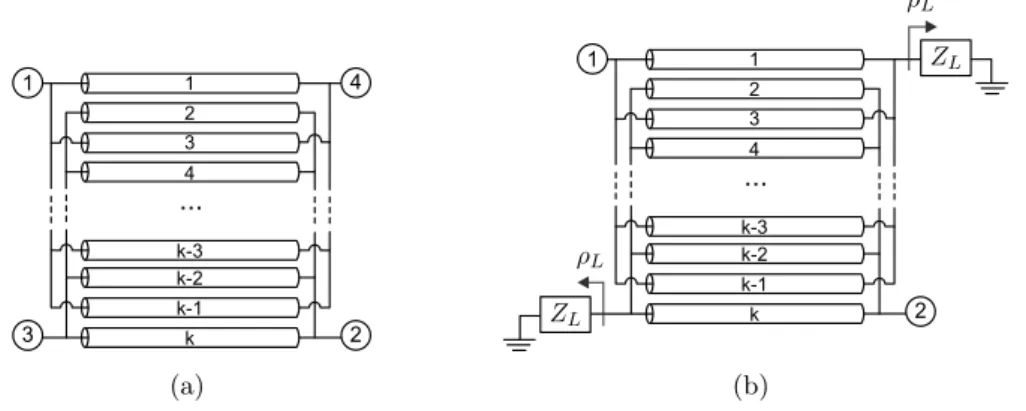
Figure 2.1.: Transmission line equivalent of (a) a four-port wire-bonded MTL and of (b) a two-port wire-bonded MTL with reactive loads at the coupled and direct ports.
and telephone because of its inherent resistance to external noise sources. Other advantages of differential signalling are reduced even-order harmonics and increased dynamic range. Consequently, baluns are important and pre-eminent devices in balanced microwave front-end circuit such as balanced mixers, push-pull amplifiers, phase shifters, balanced modulators, two-wire antennas, and other applications.
In this chapter, a thorough and comprehensive study of reflection-type phase shifters by using wire-bonded multiconductor transmission lines (MTL) is carried out. The focus of this analysis is on finding the number of conductors and the even- and odd-mode impedances of the wire-bonded MTL (Fig. 2.1(a)) to achieve a required performance according to insertion losses, return losses and operating bandwidth. Notwithstanding, given that the use of open-and short-circuited coupled lines has been fostered for realizing bopen-andpass or bopen-andstop filters [3,4], wideband baluns [5,6] and composite right/left handed transmission lines (CRLH) [7– 10], two general equivalent circuits as a function of the number of conductors and the coupling factor are presented. These two new circuits extend the known models for the classic two-strip coupled lines [3,5] and thus, they can be easily used to derive the design equations of filters based on cascaded wire-bonded MTL sections.
Furthermore, the presented theoretical analysis emphasizes the worth of employing open-and short-circuited wire-bonded MTLs to design widebopen-and baluns with good input match, amplitude and phase balance, and excellent output isolation. Many different balun topologies have been proposed in the literature [11–14], but most of them have either a narrow-band performance or poor balanced output ports matching and isolation (e.g. Marchand baluns). Therefore, based on the theory and new equivalent circuits developed in next chapter it will proved that wire-bonded MTL-based baluns overcome most of the awkward limitations of recently published baluns.
design and manufacture two critical- and over-coupling open- and short-circuited wire-bonded MTLs (-90o and +90o).
2.2. Analysis and Design Procedure
The wire-bonded MTL is a four-port device where the ends of alternate strips are connected by bonding wires (see Fig.2.1(a)). Therefore, a wire-bonded MTL is a particular configuration of multiconductor transmission lines [5,15,16]. The interconnections among alternate strips broaden the operating frequency band of the MTL by eliminating undesired resonances and allow the use of simplified analytical models. Assuming ideal short circuits across alternate conductors the equivalent model of a wire-bonded MTL can be simplified as a pair of coupled lines [4,5].
The input admittance matrix of a wire-bonded MTL was derived in [17] and design equa-tions for an interdigital directional coupler were obtained. However, a new approach is accom-plished in this work to obtain general design equations of reflection-type phase shifters based on wire-bonded MTLs. When losses are neglected and the coupling between non-adjacent strips is negligible, the admittance matrix of the wire-bonded MTL can be expressed as [17]
[YL]=j
−Mcotθ −Ncotθ Ncscθ Mcscθ
−Ncotθ −Mcotθ Mcscθ Ncscθ Ncscθ Mcscθ −Mcotθ −Ncotθ Mcscθ Ncscθ −Ncotθ −Mcotθ
(2.1)
whereθis the electrical length of the fingers, and M and N are defined by
M = k
2Y11+
k
2 −1
Y2
12
Y11
(2.2a)
N = (k−1)Y12. (2.2b)
Admittances Y11 and Y12 are calculated as
Y11=
1
2(Yoo+Yoe), Y12=−
1
2(Yoo−Yoe), (2.3)
where Yoo and Yoe represent the odd and even mode admittances, respectively, of a pair of
adjacent lines andk, which is even, stands for the number of conductors or strips in the case
of planar technology (excluding the ground plane). When no losses are considered Yoo and Yoe are real numbers and it happens that
M >0, N <0, M2 > N2. (2.4)
assumed, and that the electrical length of the fingers θ is the average value of the even- and
odd-mode electrical lengths θe and θo, given by
θ= θe+θo
2 . (2.5)
Therefore, the presented model is conditioned by several assumptions. First, pure TEM and lossless propagation are assumed, where the effective relative permittivity is computed from the values of the even- and odd- modes of a pair of adjacent conductors as
√ǫ
ref f =
√ǫ
ref f e+√ǫref f o
2 . (2.6)
Second, the coupling between non-adjacent strips is neglected. Third, the bonding wires across alternate strips are considered ideal short circuits (bonding wires very short compared to the wavelength) and thus, the connections can be neglected and the equivalent model of a wire-bonded MTL can be simplified as a pair of coupled lines [4,5,18] (see AppendixA). Finally, the model was developed for a wire-bonded MTL with an even number of conductors [17]. The validity and accuracy of these approximations have been investigated and validated in [5–7,9,18–22], where it was demonstrated an excellent agreement between experimental and analytical results.
If all the four ports are loaded with the characteristic impedanceZ0 [17,23]
Z0= √ 1
M2−N2, (2.7)
the S-parameters of the wire-bonded MTL (Fig. 2.1(a)) can be expressed as
[S] =
0 0 α β
0 0 β α
α β 0 0
β α 0 0
, (2.8)
where α andβ are computed as
α= √ csinθ 1−c2cos2θe
j(π/2+φ), β=
√ 1−c2
√
1−c2cos2θe
jφ, (2.9)
φ being
φ= arctan
−sinθ
√
1−c2cosθ
. (2.10)
cis the coupling coefficient of a quarter-wavelength k-line coupler given by
c=−N
M =
(k−1)(Z2
oe−Zoo2 )
2ZoeZoo+ (k−1)(Zoe2 +Zoo2 )
1 2 3 4
k-3 k-2 k-1
k 2
1
...
ρL
ρL
β ρLβ2
ρLβα
α ρLα2
ρLαβ
ZL
ZL Input
Output
Figure 2.2.:Transmitted and reflected signals inside a two-port wire-bonded MTL, designed by means of (2.7), with reactive loads at the coupled and direct ports.
From (2.8) it is easy to note that if (2.7) is met, the wire-bonded MTL behaves as a backward-wave directional coupler [5] with its four input ports perfectly matched, with perfect isolation between port 1-3 and 2-4, andα and β stand for the quantity of transmitted signal
to the coupled and direct ports, respectively. Therefore, when a signal is incident at port 1, the power is divided between ports 3 (α) and 4 (β) and no power reaches port 2 (see
Fig.2.1(a)). Furthermore, from (2.9) follows that the maximum value of coupling is c, that
happens atθ=90o.
One of the main applications of wire-bonded MTLs is the design of reflection type phase shifters by connecting reactive loads to the direct and coupled ports as shown in Fig.2.1(b). Traditionally a coupling factor of c=-3 dB has been employed to design the phase shifter [24,25], but in this work it is studied and verified that this is one particular solution. Hence, it is demonstrated that if the wire-bonded MTL is properly designed, any coupling levelccan
be used and that the higher the coupling factor the broader the operating frequency band. Assuming that both loadsZL are equal, the reflection coefficientρL is defined by
ρL=
ZL−Z0
ZL+Z0
=|ρL|ej∠ρL, (2.12)
and the S-parameters of the resultant two-port structure can be easily computed as
S11=ρL
α2+β2, S21= 2ρLαβ. (2.13)
The physical meaning of (2.13) is graphically illustrated in Fig. 2.2. It can be seen that the input signal is split according to α and β to the coupled and direct ports. Then, the
signals are reflected (ρL) and pass back through the wire-bonded MTL, being superimposed
manipulations, the S11and S21 parameters can be expressed as
S11=|ρL|1−
c2(1 + sin2θ)
1−c2cos2θ e
j(∠ρL+2φ) (2.14a)
S21=|ρL|
2c√1−c2sinθ
1−c2cos2θ e
j(∠ρL+2φ+π/2). (2.14b)
From (2.14) and (2.10) it is straightforward to determine that the coupling factorc
condi-tions both the input match (2.14a) and insertion loss (2.14b), but also the slope of the phase response (2.10). However, from these relationships it follows that if (2.7) is satisfied and two identical variable reactive loads are employed with |ρL|=1, any coupling factor c could be
used to design a tunable phase shifter. The coupling level c determines the insertion and
return losses, but clearly the use of c=-3 dB is one out of the possible solutions. The relative phase difference between the output and the input signals can be controlled and adjusted by the phase of the reactive loads. Besides, from (2.14a) the following relation is obtained
θd= arcsin
r 1
c2 −1
!
, (2.15)
that establishes the electrical lengthsθdwhere the input match is perfect (S11=0) as a function
of c. Figure 2.3(a) draws the magnitude of S11 and S21 for several coupling values, and as
can be deduced from (2.15), only for values of c greater than 1/√2 the wire-bonded MTL
is perfectly matched, at one, c= 1/√2 (c=-3 dB), or two frequencies c >1/√2 (c <-3 dB).
As a result, the wire-bonded MTL can be designed to have either a flat (θd=90o) or a ripple
response (θd6=90o). This behaviour in frequency can be easily explained and understood if we
think that the input port is only matched when equal power split between the coupled and direct ports is maintained (|α|=|β|= 1/√2) and the superimposed signals at the input port are anti-phase and thus cancel (2.9)(2.14). Therefore, at the frequencies where the loaded wire-bonded MTL is matched, the coupling level α is always -3 dB, but only when θd=90o
happens thatα=c=-3 dB. Consequently, it is clear that if we refer toc, an over-coupled wire-bonded MTL is required to have perfect match at a value of θd6=π/2 (α=-3 dB,c <-3 dB).
If we analyze the wire-bonded MTL forθ=θd (2.15), the following relations are obtained
αθd =
1 √
2e
j(φθd+π/2), β
θd =
1 √
2e
jφθd, φ
θd=−arctan
q
1 + 2 tanθ2
d
, (2.16)
and consequently |S11|=0 and |S21|=1 (2.13). Finally, Fig. 2.3(b) represents the phase of
S21 when ZL = ∞ (ρL=1) and ZL = 0 (ρL=-1) for several c values. It is noticeable that
for a particular ZL, all curves take the same value at θ=π/2, but their slope depend on c.
Besides, it is seen that by controlling the reactive loads it is possible to adjust the phase of
0 0.5 1 1.5 2 0 0.1 0.2 0.3 0.4 0.5 0.6 0.7 0.8 0.9 1
θ 0 π/4 π/2 3π/2 π
S11 S21
|
S11
|
or
|
S21
|
c= -5 dB
c= -3 dB
c= -2 dB
f /fo
(a)
0 0.5 1 1.5 2
-270 -180 -90 0 90 180 270
ρL=-1
ρL=1
θ 0 π/4 π/2 3π/2 π
c c
c= -5 dB
c= -3 dB
c= -2 dB
∠
S21
(
o)
f /fo
(b)
Figure 2.3.: (a) Magnitude of S11 and S21, and (b) phase of S21 of a wire-bonded MTL
designed by means of (2.7) with two identical reflection loads ZL (|ρL|= 1) at its coupled
and direct ports (Figure 2.1(b)) for several coupling values. For the phase of S21, ZL=∞
(ρL=1) andZL=0 (ρL=-1) have been used.
The preceding analysis is specially useful and provides some insight into the design of compact wire-bonded MTLs. As known, the operating bandwidth is maximum when the electrical length of the wire-bonded MTL isπ/2 at the center design frequency, but a shorter
MTL with perfect input match at the design frequency can be also achieved by means of (2.15). For example, if we want to use a wire-bonded MTL of length λ/8, the structure can
be easily designed by solving (2.15) for θd=π/4. In that case, the necessary coupling factor c
should be -1.76 dB andθd corresponds to the center frequency fo. However, it is important
to remark that this design solution has only relevance for narrow operating bandwidths because the symmetric bandwidth respect to the center design frequency will be reduced. This behaviour can be observed in Fig.2.4(a), where the input and return loss of two wire-bonded MTLs designed for two coupling levels, -1 dB and -2 dB, and their associated bandwidths of operation are represented. The length of both MTLs is 0.085λ (θ=30.6o) and 0.25λ (θ=90o)
at the design frequency fo, for c=-1 dB and c=-2 dB, respectively. Therefore, the size of
the -1 dB wire-bonded MTL is reduced by 66% compared to that of the -2 dB MTL, but its operating bandwidth is extremely narrowed. This design approach could be also used to obtain compact dual-band phase shifting sections, beingθd and π−θd the electrical lengths
at the dual design center frequencies.
However, it is worth to mention that these coupling factors imply some practical limitations in order to achieve the required high even- and odd-modes impedances values. Therefore, the use of wire-bonded MTLs is advisable to achieve such tight coupling factors that would be unapproachable with only two strips without any backside aperture. If k=2, by using
the design equations (2.7), (2.11) and (2.15) for the wire-bonded MTL of length 0.085λ, it
-30 -25 -20 -15 -10 -5 0 BW BW
θd=30.6o θd=50o
0 π/4 π/2 3π/2 π
S11lim
S11 S21
c= -2 dB
c= -1 dB
S1 1 or S2 1 (d B ) θ(rad) fo fo (a)
-4.5 -4 -3.5 -3 -2.5 -2 0 20 40 60 80 100 120 140 cmax cmin
S11lim=-30 dB S11lim=-20 dB S11lim=-15 dB S11lim=-10 dB
F B W (% ) c(dB) (b)
Figure 2.4.: (a) Magnitude of S-parameters and associated bandwidths (BW for S11 <
-10 dB) for two wire-bonded MTLs with length 0.085λ and 0.25λ at the design frequency fo. (b) Operating bandwidth of a quarter-wavelength wire-bonded MTL as a function of the
coupling level that guarantees that the minimum insertion loss is under a threshold limit valueS11lim(dB)=[-30, -20, -15, -10].
presented in [26], where a coupled structure of length 0.083 λ is employed. However, in
[26] authors carry out a parametric study to obtain the values of such even- and odd-mode impedances for two lines, while in this work we provide general closed-form design equations that can be easily employed to obtain the mode impedances for any length and irrespective of the number of conductors.
From Fig. 2.3(a) and Fig. 2.4(a), we can also observe that if a quarter-wavelength wire-bonded MTL is considered at the design center frequency (θ=π/2), there are two limit cou-pling factors, minimum and maximum factors, in order to guarantee that return losses at mid-band frequency are under a threshold value. Being S11lim the threshold limit value, the
minimum and maximum allowed coupling factors can be computed as
c2 = 1∓S11lim
2 (2.17)
Thus from (2.17), if a typical limit value of S11 = 10−1/2 (-10 dB) is used, we obtain
c=-4.66 dB and c=-1.82 dB, approximately, as the limit coupling values that could be used
to design the quarter-wave wire-bonded MTL. Furthermore, the associated bandwidths can be easily computed as
F BW(%) = 200 1− 2
πarccos
s
2c2−1 +S 11lim c2(1 +S
11lim)
!
. (2.18)
The result of evaluating (2.18) for several threshold limit values S11lim is depicted in
of operation are reduced as S11lim decreases. Therefore, taking into account the presented
study, it can be concluded that any coupling factorc within the limit values determined by (2.17) can be used for designing phase-shifting sections, but that there is a trade-off between the selected coupling factor and both, the bandwidth and the insertion loss.
2.3. Open- and Short-Circuited Wire-Bonded MTL
In previous section, a wire-bonded MTL loaded with reactive loads at the coupled and direct ports has been analyzed and some design rules have been deduced as a function of the coupling factor. However, in this point the study is extended for two particular arrangements, when two open or short circuits are used as loads. These two configurations are widely employed in designing filters, baluns, impedance transformers, DC blocks, interdigital capacitors, and spiral inductors [3–10]. Therefore, two general equivalent circuits for the open- and short-circuited wire-bonded MTL that provide some physical insight into their frequency behaviours and that can be easily used by designers, are obtained in this section.
By using the admittance matrix of a four-port wire-bonded MTL [17], and after some algebraic manipulations, it is straightforward to obtain the following equations for the two-port loaded wire-bonded MTLs,
[Z]oc=j 1 N
c
c+ 1cotθ
" 1 0 0 1
# −j 1
N c2 c2−1
"
cotθ cscθ
cscθ cotθ
#
(2.19)
[Y]sc=jN1−c c cotθ
" 1 0 0 1
# +jN
"
cotθ cscθ
cscθ cotθ
#
(2.20)
whereZ andY are the impedance and admittance matrices, and subscriptsoc andscstand
for the open-circuited and short-circuited MTL, respectively. Now, from (2.19) and (2.20), it is worth to notice that both devices are equivalent to a circuit consisting of a transmission-line section with two stubs, series open stubs for the open-circuited MTL, and shunt short stubs for the short-circuited MTL. These equivalent circuits are shown in Fig. 2.5, where it is remarkable that, while the electrical length of the main line for the open-circuited MTL is
θ, the equivalent transmission line for the short-circuited MTL isθ+π. Therefore, there is
an additional 180-degrees phase shift because of the short-circuited ends of the wire-bonded MTL [5].
1 2 2
1
...
θ Z
Soc,θ
Z0oc,θ
(a)
1 2
2 1
...
θ
ZSsc,θ
Z0sc,θ+π
(b)
Figure 2.5.: Equivalent circuits for (a) open-circuited and (b) short-circuited wire-bonded MTLs.
circuits (see Fig. 2.5) for the open- and short-circuited wire-bonded MTLs are given by
Z0oc=
−1
N c2
1−c2=
(k−1) (Zoe−Zoo) (Zoe+Zoo)2
2 [(k−1)Zoe+Zoo] [(k−1)Zoo+Zoe] (2.21a)
ZSoc=
−1
N c
1 +c =
Zoo(Zoe+Zoo)
(k−1)Zoe+Zoo
(2.21b)
Z0sc =
−1
N =
2ZoeZoo
(k−1) (Zoe−Zoo) (2.22a)
ZSsc =
−1
N c
1−c =
Zoe(Zoe+Zoo)
(k−1)Zoo+Zoe
. (2.22b)
Whenk=2, these equations simplify to
Z0oc =
Zoe−Zoo
2 , ZSoc =Zoo, Z0sc =
2ZoeZoe Zoe−Zoe
, ZSsc =Zoe, (2.23)
that are equal to the given in [3, 5] for a two-line coupled-line section. Furthermore, as can be seen in Fig. 2.5, whenθ=90 degrees the stubs in both equivalent circuits appear as open
circuit across the main transmission line [5]. Therefore, from (2.21a) and (2.22a), it is easy to deduce that a quarter-wavelength open- or short-circuited wire-bonded MTL is advisable to synthesize low- or high-impedance transmission line sections, respectively, with characteristic impedances Z0oc and Z0sc.
short-circuited wire-bonded MTLs: their duality. Both MTLs, when properly designed, are dual circuits and thus, are suited for implementing planar broadband baluns. In that sense, the equivalent circuits shown in Fig.2.5, are useful to design both MTLs.
2.4. Experimental Results
To validate the theory and analysis carried out in Sections2.2and2.3, two quarter-wavelength opencircuited and shortcircuited wirebonded MTLs with coupling factors of 3 dB and -2.6 dB, are designed, manufactured and measured at a design frequency offo=3.5 GHz with
a characteristic impedance Z0=50 Ω (2.7)(2.2)(2.11). These coupling factors, critical- and
over-coupling levels, are computed according to (2.15) to have one or two frequencies of maximum input match within the operating frequency band at approximately θd=90o and θd=65o, respectively.
The employed substrate is Rogers 4350B with a relative permittivity of 3.66 and thickness of 30 mil. Two six-line (k=6) wire-bonded MTLs with a length of 13.6 mm are designed, the first one with a line-width (W) of 121µm and spacing (S) of 131µm for c=-3 dB, and the
second one withW=114 µm andS=106 µm forc=-2.6 dB. The number of strips kis chosen taking into account the required tight coupling values and it is conditioned by our fabrication capability, which limits the minimum widthW and spacingSbetween conductors to 100 µm.
Figure2.6represents the measured S-parameters for both open- and short-circuited MTLs. The magnitude of S11 and S21 parameters are depicted in Fig. 2.6(a) and Fig.2.6(b), while
the phase ofS21is shown in Fig.2.6(c). From these curves, it is possible to observe the very
good agreement between the theory presented in Section 2.2 and the measurements. The theoretical operating bandwidths, computed by means of (2.18) and consideringS11=-10 dB
1 2 3 4 5 6 -45 -40 -35 -30 -25 -20 -15 -10 -5 0 S21 S11
c=-3 dB c=-2.6 dB
S1
1
or
S21
(d
B
)
Frequency (GHz)
(a)
1 2 3 4 5 6
-45 -40 -35 -30 -25 -20 -15 -10 -5 0 S21 S11
c=-3 dB c=-2.6 dB
S11
or S2 1 (d B ) Frequency (GHz) (b)
1 2 3 4 5 6
-180 -135 -90 -45 0 45 90 135 180 c c c c
c=-3 dB c=-2.6 dB
∠ S2 1 ( o) Frequency (GHz) (c)
Figure 2.6.: Measured magnitude of S11 and S21 of the manufactured six-line (a)
open-circuited and (b) short-open-circuited wire-bonded MTLs. (c) Phase of S21 for the fabricated
open- and short-circuited MTLs (c=[-2.6,-3] dB).
2.5. Conclusion
baluns, impedance transformers, and other microwave circuits. The analytical study carried out has been assessed by designing and manufacturing two critical- and over-coupling open-and short-circuited wire-bonded MTLs.
References
[1] R. Garver, “Broad-band diode phase shifters,”IEEE Trans. Microw. Theory Tech., vol. 20, no. 5, pp. 314 – 323, May 1972.
[2] I. D. Robertson and S. Lucyszyn,RFIC and MMIC Design and Technology. London, UK: IEE Press, 2001.
[3] G. L. Mattahei, L. Young, and E. M. T. Jones, Microwave Filters, Impedance-Matching Networks, and Coupling Structures, M. A. House, Ed. Norwood, 1985.
[4] D. Pozar,Microwave Engineering, 2nd ed. New York: Wiley, 1998.
[5] R. Mongia, I. Bahl, and P. Bhartia,RF and Microwave Coupled-Line Circuits. Norwood, MA: Artech House, 1999.
[6] J. J. Sánchez-Martínez and E. Márquez-Segura, “Generalized analytical design of broadband planar baluns based on wire-bonded multiconductor transmission lines,”Progr. Electromagn. Res., vol. 134, pp. 169–187, 2013.
[7] J. J. Sánchez-Martínez, E. Márquez-Segura, P. Otero, and C. Camacho-Peñalosa, “Artificial Transmission Line with Left/Right-Handed Behavior Based on Wire Bonded Interdigital Capacitors,”Progr. Electro-magn. Res. B, vol. 11, pp. 245–264, 2009.
[8] A. Safwat and T. M. Abuelfadl, “Coupled lines from filter to composite right/left handed-cells,”Progr. Electromagn. Res. B, vol. 26, pp. 451–469, 2010.
[9] J. J. Sánchez-Martínez and E. Márquez-Segura, “Analytical Study of Wide-band Bandpass Filters Based on Wire-Bonded Multiconductor Transmission Lines With LH Behaviour,” Progr. Electromagn. Res. Lett., vol. 31, pp. 1–13, 2012.
[10] J. J. Sánchez-Martínez, E. Márquez-Segura, and C. Camacho-Peñalosa, “Synthesis of CRLH-TLs Based on a Shunt Coupled-line Section,” in 42nd European Microwave Conference (EuMC), Oct. 2012, pp. 675–678.
[11] Z.-Y. Zhang, Y.-X. Guo, L. C. Ong, and M. Chia, “A new wide-band planar balun on a single-layer pcb,” IEEE Microw. Wireless Compon. Lett., vol. 15, no. 6, pp. 416–418, Jun. 2005.
[12] C.-H. Tseng and C.-L. Chang, “Wide-band balun using composite right/left-handed transmission line,” Electron. Lett., vol. 43, no. 21, pp. 1154–1155, Nov. 2007.
[13] R. Phromloungsri, M. Chongcheawchamnan, and I. Robertson, “Inductively compensated parallel coupled microstrip lines and their applications,”IEEE Trans. Microw. Theory Tech., vol. 54, no. 9, pp. 3571–3582, Sep. 2006.
[14] J.-L. Li and S.-W. Qu, “Miniaturised branch-line balun with bandwidth enhancement,”Electron. Lett., vol. 43, no. 17, pp. 931–932, Aug. 2007.
[15] J. A. B. Faria,Multiconductor Transmission-line Structures: Modal Analysis Techniques. New York: Wiley, 1993.
[17] W. Ou, “Design Equations for an Interdigitated Directional Coupler,” IEEE Trans. Microw. Theory Tech., vol. 23, no. 2, pp. 253–255, Feb. 1975.
[18] C.-S. Lin, P.-S. Wu, M.-C. Yeh, J.-S. Fu, H.-Y. Chang, K.-Y. Lin, and H. Wang, “Analysis of multicon-ductor coupled-line marchand baluns for miniature mmic design,” IEEE Trans. Microw. Theory Tech., vol. 55, no. 6, pp. 1190–1199, Jun. 2007.
[19] D. Kajfez and B. Vidula, “Design equations for symmetric microstrip dc blocks,”IEEE Trans. Microw. Theory Tech., vol. 28, no. 9, pp. 974–981, Sep. 1980.
[20] F. Casares-Miranda, P. Otero, E. Márquez-Segura, and C. Camacho-Peñalosa, “Wire Bonded Interdigital Capacitor,”IEEE Microw. Wireless Compon. Lett., vol. 15, no. 10, pp. 700–702, Oct. 2005.
[21] E. Márquez-Segura, F. Casares-Miranda, P. Otero, C. Camacho-Peñalosa, and J. Page, “Analytical Model of the Wire-Bonded Interdigital Capacitor,”IEEE Trans. Microw. Theory Tech., vol. 54, no. 2, pp. 748– 754, Feb. 2006.
[22] J. Page, E. Márquez-Segura, F. Casares-Miranda, J. Esteban, P. Otero, and C. Camacho-Peñalosa, “Exact Analysis of the Wire-Bonded Multiconductor Transmission Line,”IEEE Trans. Microw. Theory Tech., vol. 55, no. 8, pp. 1585–1592, Aug. 2007.
[23] A. Presser, “Interdigitated microstrip coupler design,”IEEE Trans. Microw. Theory Tech., vol. 26, no. 10, pp. 801–805, Oct. 1978.
[24] S. Lucyszyn and I. Robertson, “Synthesis techniques for high performance octave bandwidth 180 deg; analog phase shifters,”IEEE Trans. Microw. Theory Tech., vol. 40, no. 4, pp. 731 –740, Apr. 1992.
[25] ——, “Analog reflection topology building blocks for adaptive microwave signal processing applications,” IEEE Trans. Microw. Theory Tech., vol. 43, no. 3, pp. 601 –611, Mar. 1995.
Baluns
T
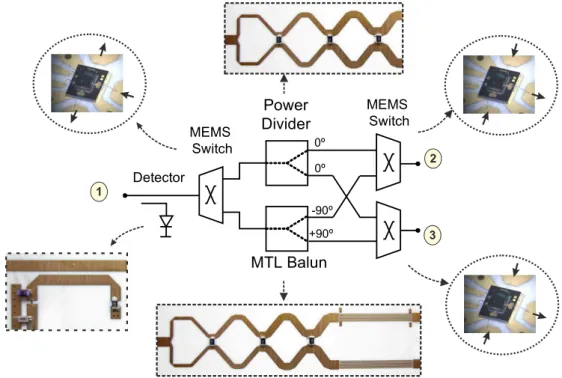
hetheoretical analysis presented in Chapter2emphasizes the worth of employingopen-and short-circuited wire-bonded MTLs to design widebopen-and baluns with good input match, amplitude and phase balance. Thus, in Section3.2a novel generalized design procedure of broadband planar baluns based on wire-bonded multiconductor transmission lines (MTL) is presented. The proposed balun consists of two parts. The first one is an in-phase power divider, which equally splits the input power through its two outputs. The later are two MTLs with wire bonding between alternate conductors configured to introduce +90 and -90 degrees phase shift respectively, so that the balanced output signal has a 180 degree phase difference. In Section 3.2.2 design equations in order to calculate the design parameters of both multiconductor elements are obtained. These equations allow the proper dimensions of both MTLs to be computed irrespective of the number of conductors and the coupling factor. Thus, in Section3.2.4, a prototype of such balun is fabricated to validate the theory.
Finally, a reconfigurable test set for the characterization of differential devices by using a commercial two-port vector network analyzer is presented in Section3.3. The MTL balun is used to convert single-ended input signals to differential signals, providing the required good port matching and high reverse isolation.
3.1. Introduction
1
3
...
...
...
...
2
1 2
3
1 2
1 2
MTL
MTL
W S ℓ
Power Divider
180oPhase Shifter
Figure 3.1.: Architecture of the balun consisting of an in-phase power divider and two wire-bonded multiconductor transmission lines. A snapshot of a wire-wire-bonded MTL in microstrip technology is included.
the literature, but it is possible to establish two main groups. The first group comprises those baluns that consists of an equal in-phase power divider connected to a phase-shifting section to achieve the required 180-degree phase difference at the output ports. The second group consists of baluns that are designed from a symmetric four-port circuit with one of its ports open-circuited, short-circuited or loaded with an arbitrary impedance. Within the first group, some examples can be found in [1–3]. In [1], a noncoupled-line 180o phase shifter was
connected to the outputs of the divider and a composite right/left-handed transmission line was used in [2, 3]. However, the main drawback of these baluns is to achieve a good phase balance in a wide frequency band. Respect to the second group, we can include Marchand baluns [4–12], branch-line baluns [13, 14] and other circuits based on the same principle [15–18]. Among these baluns, Marchand baluns are probably the most popular. Marchand balun consists of two sections of quarter-wavelength coupled lines and in order to broaden the bandwidth a strong coupling level for the two coupled-line sections is required [19]. However, the main limitation is its poor balanced output ports matching and isolation. Therefore, based on the theory and new equivalent circuits developed in Chapter 2, it is proved that wire-bonded MTL-based baluns overcome most of the awkward limitations of recently published baluns.
isolation. The last condition improves the main Marchand balun drawback, its poor balanced output ports matching and isolation [23]. For the phase shifter section, short-circuited and open-circuited coupled lines have been employed in [20] and [21] but, there is lack of both a design procedure and analysis for wire-bonded multiconductor transmission lines (MTL). The presented balun circumvents the limited output isolation and narrow operating bandwidth of most of the recently published baluns. Consequently, the use of wire-bonded MTLs is advisable in designing wideband baluns because both short- and open-circuited MTLs are dual components (see Fig.2.6), and if they are properly designed a perfect theoretical output amplitude and phase balance can be achieved at all frequencies.
3.2. Analysis and Design Procedure
3.2.1. Balun Architecture
The circuit schematic of the proposed planar balun, consisting of a power divider connected to two wire-bonded multiconductor transmission lines, is sketched in Fig.3.1. The power divider splits the input signal into two equal amplitude in-phase signals. Then, the two output signals pass through a pair of short-circuited and open-circuited MTLs configured to introduce +90 and -90 degrees phase shift respectively, over each signal. Therefore, output signals have equal amplitude and 180 degrees phase difference. According to the power divider, the Wilkinson divider seems to be a good choice because it provides equal power split, high output ports isolation and good match at all three ports. Besides, the Wilkinson can be designed with multiple stages in order to enlarge its bandwidth and fulfill the frequency band requirements.
3.2.2. Theoretical Study
A wire-bonded multiconductor transmission line is a four-port device and its input admittance matrix can be found in [24]. By placing open- or short-circuits at its diagonal ports, the two-port circuits drawn in the insets of Fig.3.1are obtained. These two circuits were previously analyzed in Section 2.3 and two equivalent circuit models were derived. Nevertheless, the study carried out in this section gives us some insights into the physical behaviour of both MTLs and provides the necessary analytical equations to properly design the proposed balun. When losses are neglected and coupling between non adjacent strips is negligible, both devices are characterized by the following admittance matrices
[Y]o=
(M2−N2) sinθ M2cos2θ−N2
"
jMcosθ jN
jN jMcosθ
#
(3.1)
[Y]s=
1 sinθ
"
−jMcosθ jN
jN −jMcosθ
#
where the subscripts oand sstand for the open-circuit or short-circuit boundary conditions
respectively.θis the electrical length of the conductors (2.5), andM and N, defined in (2.2), can be written as
M = (k−1)(Zoe2 +Zoo2 ) + 2ZoeZoo
2(Zoe+Zoo)ZoeZoo
, N = (k−1)(Zoo−Zoe) 2ZoeZoo
, (3.3)
where Zoe andZoo are the odd and even modes impedances of a pair of adjacent lines andk
relates to the number of strips. It is important to remark that in previous equations it has been considered that both wire-bonded MTLs are equal and only the boundary conditions, short-circuit or open-circuit, are changed. Besides, pure TEM and lossless propagation are assumed, beingθthe average value of the even- and odd-mode electrical lengths (Section2.2).
The propagation constant of the two-port structures obtained can be calculated from (3.1) and (3.2) as [25]
cosh(γℓ) = (Y11Y22)
1/2
Y21
, (3.4)
being ℓthe length of the MTL. When both wire-bonded MTLs are assumed lossless (3.4) is
simply given by
βoℓ= cos−1
−MN cosθ
, βsℓ= cos−1
M
N cosθ
(3.5)
where clearly it is observed that βs = βo +π. Thus, the output signals of the open- and
short-circuited MTLs are always 180 degree out-of-phase at all frequencies. Nevertheless, such equations are deduced considering that input and output ports are perfectly matched. The image impedances of both circuits can be calculated from (3.1) and (3.2) as
ZIo =
N2−M2cos2θ1/2
(M2−N2) sinθ , ZIs =
sinθ
(N2−M2cos2θ)1/2 (3.6)
As seen, both image impedances are different and depend on the electrical length of the MTL. Consequently, it is necessary to find out some design rule in order to obtain 180 degrees differential phase and equal amplitude outputs. By means of simple transformations [25] and after some algebraic manipulations, the reflection S11 and transmission S21 coefficients of
each wire-bonded MTL (see the insets in Fig. 3.1) are given by
S11i=
Ki2(N2−M2cos2θ)−Z02
∆i
(3.7a)
S21i=
2GiKiZ0N
j∆i
, (3.7b)
where Z0 is the reference impedance, the subindex i can be o or s depending on whether


![Table 3.3.: Comparisons among some published baluns and the designed balun. Ref f o (GHz) BW (%) I (dB) PB ( o ) AB (dB) [1] 2.4 64 >15 ±5 0.3 [2] 2 76 ±10 0.7 [3] 0.915 49 >16 ±6 0.5 [4] 13 77 ±4 1 [5] 1.2 35 >15 ±5 0.6 [6] 1 64 ±2 0.2 [7] 0.9 44](https://thumb-us.123doks.com/thumbv2/123dok_es/6357535.783808/53.892.220.691.190.701/table-comparisons-published-baluns-designed-balun-ref-ghz.webp)