SOLUCIÓN DE ESTUDIOS DE CASOS BAJO EL USO DE TECNOLOGÍA CISCO
FRANCISCO ALDEMAR OLIVA GUEVARA
UNIVERSIDAD ABIERTA Y A DISTANCIA UNAD
ESCUELA CIENCIAS BÁSICAS, TECNOLOGÍA E INGENIERÍA ECBTI DIPLOMADO CISCO
SOLUCIÓN DE ESTUDIOS DE CASOS BAJO EL USO DE TECNOLOGÍA CISCO
FRANCISCO ALDEMAR OLIVA GUEVARA
Diplomado en redes como opción de grado
GIOVANNI ALBERTO BRACHO TUTOR
UNIVERSIDAD ABIERTA Y A DISTANCIA UNAD
ESCUELA CIENCIAS BÁSICAS, TECNOLOGÍA E INGENIERÍA ECBTI DIPLOMADO CISCO
Valle del Guamuéz 19, dic, 2018)
NOTA DE ACEPTACION
______________________________ ______________________________ ______________________________ ______________________________ ______________________________ ______________________________ ______________________________
______________________________ Presidente del jurado
AGRADECIMIENTOS
Doy gracias a Dios principalmente por permitirme culminar con éxito los estudios. Al tutor Giovanni Alberto Bracho por su apoyo y dedicación.
A mi esposa, mis padres, mis hermanos y compañeros por su ayuda incondicional.
TABLA DE CONTENIDO
INTRODUCIÓN _________________________________________________________ 8
OBJETIVOS _____________________________________________________________ 9
DESARROLLO DE LOS ESCENARIOS 1 y 2 ________________________________ 10
1. Escenario 1 ________________________________________________________ 10
1.2 Los puertos de red que no se utilizan se deben deshabilitar. _________________ 12
1.3 La información de dirección IP R1, R2 y R3 debe cumplir con la tabla ... 12
1.3.1 Configuración del ISP ... 12
1.3.2 Configuración de R1 ... 13
1.3.3 Configuración de R2 ... 14
1.3.4 Configuracion R 3 ... 16
1.4 Laptop20, Laptop21, PC20, PC21, Laptop30, Laptop31, PC30 y PC31 deben obtener información IPv4 del servidor DHCP. ... 17
1.5 R1 debe realizar una NAT con sobrecarga sobre una dirección IPv4 pública. ... 19
1.6 R1 debe tener una ruta estática predeterminada al ISP que se configuró y que incluye esa ruta en el dominio RIPv2. ... 19
R2 es un servidor de DHCP para los dispositivos conectados al puerto FastEthernet0/0. .... 19
1.7 R2 debe, además de enrutamiento a otras partes de la red, ruta entre las VLAN 100 y 200. 20 1.8 El Servidor0 es sólo un servidor IPv6 y solo debe ser accesibles para los dispositivos en R3 (ping). ... 20
1.9 La NIC instalado en direcciones IPv4 e IPv6 de Laptop30, de Laptop31, de PC30 y obligación de configurados PC31 simultáneas (dual-stack). ... 21
1.10 La interfaz FastEthernet 0/0 del R3 también deben tener direcciones IPv4 e IPv6 configuradas (dual- stack). ... 21
1.11 R1, R2 y R3 intercambian información de routing mediante RIP versión 2. ... 22
1.12 R1, R2 y R3 deben saber sobre las rutas de cada uno y la ruta predeterminada desde R1. ... 23
1.13 Verifique la conectividad. Todos los terminales deben poder hacer ping entre sí y a la dirección IP del ISP. Los terminales bajo el R3 deberían poder hacer ipv6-ping entre ellos y el servidor. ... 23
_______________________________________________________________________ 25
2.1. Configurar el direccionamiento IP acorde con la topología de red para cada uno de
los dispositivos que forman parte del escenario ... 26
2.1.1 Configuración del direccionamiento ip de Internet PC ... 26
2.1.2 Configuración de Web Server ... 26
2.1.3 Configuración de R1 ... 26
2.1.4 Configuración del R2 ... 27
2.1.5 Configuración del R3 ... 28
2.1.6 Configuración de “S1” ... 29
2.1.7 Configuración de “S3” ... 29
2.1.8 Configuración del direccionamiento ip de “PC-A” ... 29
2.1.9 Configuración del direccionamiento ip de “PC-C” ... 30
2.2 Configurar el protocolo de enrutamiento OSPFv2 bajo los siguientes criterios: ... 30
2.2.1 Configuración en R1 ... 30
2.2.2 Configuración en R2 ... 31
2.2.3 Configuración en R3 ... 31
Visualizar tablas de enrutamiento y routers conectados por OSPFv2 ... 32
2.4 Visualizar lista resumida de interfaces por OSPF en donde se ilustre el costo de cada interface ... 32
2.5 Visualizar el OSPF Process ID, Router ID, Address summarizations, Routing Networks, and passive interfaces configuradas en cada router. ... 32
2.6 Configurar VLANs, Puertos troncales, puertos de acceso, encapsulamiento, Inter-VLAN Routing y Seguridad en los Switches acorde a la topología de red establecida. ... 33
2.6.1 Se configuramos la seguridad en R1 ... 33
2.6.2 Seguridad en el router R2 ... 33
2.6.3 Configuración de seguridad en R3 ... 34
2.6.4 Configuración de seguridad en S1 ... 34
2.6.5 Seguridad en S3 ... 34
2.6.6 Configuracion de vlan en S1 ... 35
2.6.7 Configuración vlan en S3 ... 36
2.7 En el Switch 3 deshabilitar DNS lookup ... 37
2.8 Asignar direcciones IP a los Switches acorde a los lineamientos. ... 37
2.8.1 Configuración de direcciones IP en S1 ... 37
2.8.2 Configuración de direcciones IP en S3 ... 37
2.9 Desactivar todas las interfaces que no sean utilizadas en el esquema de red. ... 38
2.9.1 Desactivar interfaces en S1 ... 38
2.9.2 Desactivar interfaces en S3 ... 38
2.10 Implement DHCP and NAT for IPv4 ... 39
2.11 Configurar R1 como servidor DHCP para las VLANs 30 y 40. ... 39
2.12 Reservar las primeras 30 direcciones IP de las VLAN 30 y 40 para configuraciones estáticas. ... 40
2.14 Configurar al menos dos listas de acceso de tipo estándar a su criterio en para restringir o permitir tráfico desde R1 o R3 hacia R2. ... 41
2.15 Configurar al menos dos listas de acceso de tipo extendido o nombradas a su criterio en para restringir o permitir tráfico desde R1 o R3 hacia R2. ... 41
2.16 Verificar procesos de comunicación y redireccionamiento de tráfico en los routers mediante el uso de Ping y Traceroute. ... 42
CONCLUSIONES _______________________________________________________ 43
INTRODUCIÓN
Las redes de comunicación, nos ayudan a comunicarnos con personas de diferentes partes
del mundo, es una herramienta fundamental, que con ella podemos trabajar desde casa,
estudiar, hacer llamadas y video llamadas, estar informados de las cosas que pasan por el
mundo entero, también hacer negocios.
A continuación en esta actividad conoceremos sobre implementación NAT, de los
servidores DHCP, RIPV2 y el Routing entre VLAN, los enlaces troncales y los códigos
OBJETIVOS
Desarrollar los dos escenarios planteados con su respectiva documentación de cada proceso
realizado como son:
El escenario uno configuración de PAT, servidor DHCP configuración de vlan,
direcciones trocales con su debida documentación en IPv4 y IPv6.
Escenario dos configuración de dirección IP protocolos de enrutamiento OSPFv2
listas de acceso, creación y configuración de Vlan puertos trocales y DHCP en
DESARROLLO DE LOS ESCENARIOS 1 y 2
1.
Escenario 1
Tabla de direccionamiento
El administr ador
Interfaces Dirección IP Máscara de subred y Gatewa predetermi nado
ISP S0/0/0 200.123.211.1 255.255.255.0 N/D
R1
Se0/0/0 200.123.211.2 255.255.255.0 N/D
Se0/1/0 10.0.0.1 255.255.255.252 N/D
Se0/1/1 10.0.0.5 255.255.255.252 N/D
R2
Fa0/0,100 192.168.20.1 255.255.255.0 N/D
Fa0/0,200 192.168.21.1 255.255.255.0 N/D
Se0/0/0 10.0.0.2 255.255.255.252 N/D
Se0/0/1 10.0.0.9 255.255.255.252 N/D
R3
Fa0/0 192.168.30.1 255.255.255.0 N/D
2001:db8:130::9C0:80F:3 01
/64 N/D
Se0/0/0 10.0.0.6 255.255.255.252 N/D
Se0/0/1 10.0.0.10 255.255.255.252 N/D
SW2 VLAN 100 N/D N/D N/D
VLAN 200 N/D N/D N/D
Tabla de asignación de VLAN y de puertos
Tabla de enlaces troncales
Dispositivo local
Interfaz local
Dispositivo remoto
SW2 Fa0/2-3 100
Situación
En esta actividad, demostrará y reforzará su capacidad para implementar NAT, servidor de DHCP, RIPV2 y el routing entre VLAN, incluida la configuración de direcciones IP, las VLAN, los enlaces troncales y las subinterfaces. Todas las pruebas de alcance deben realizarse a través de ping únicamente.
Descripción de las actividades
1.1SW1 VLAN y las asignaciones de puertos de VLAN deben cumplir con la tabla
1.
Switch> enable Switch# config t
PC20 NIC DHCP DHCP DHCP
PC21 NIC DHCP DHCP DHCP
PC30 NIC DHCP DHCP DHCP
PC31 NIC DHCP DHCP DHCP
Laptop20 NIC DHCP DHCP DHCP
Laptop21 NIC DHCP DHCP DHCP
Laptop30 NIC DHCP DHCP DHCP
Laptop31 NIC DHCP DHCP DHCP
Dispositivo VLAN Nombre Interf
az
SW2 100 LAPTOPS Fa0/2-3
SW2 200 DESTOPS Fa0/4-5
Enter configuration commands, one per line. End with CNTL/Z. Switch(config)# no ip domain-lookup
Switch(config)# hostname S2 S2(config)# vlan 100
S2(config-vlan)# no shut
% Invalid input detected at '^' marker. S2(config-vlan)# exit
S2(config)# int vlan100 S2(config-if)#
%LINK-5-CHANGED: Interface Vlan100, changed state to up
S2(config-if)# exit
S2(config)# int range f0/2-3
S2(config-if-range)# switchport access vlan 100 S2(config-if-range)#exit
S2(config)# vlan 200 S2(config-vlan)# exit S2(config)# int range f0/4-5
S2(config-if-range)# switchport access vlan 200 S2(config-if-range)# exit
S2(config)# no shut
1.2 Los puertos de red que no se utilizan se deben deshabilitar.
S2(config-if-range)# int range f0/6-24 S2(config-if-range)# shutdown
%LINK-5-CHANGED: Interface FastEthernet0/6, changed state to administratively down
S2(config-if-range)# exit
1.3
La información de dirección IP R1, R2 y R3 debe cumplir con la
tabla
1.3.1 Configuración del ISP
Router> ENABLE Router# config t
Enter configuration commands, one per line. End with CNTL/Z. Router(config)# no ip domain-lookup
ISP(config)# li con 0
ISP(config-line)# password cisco ISP(config-line)# login
ISP(config-line)# logging synchronous ISP(config-line)# exit
ISP(config)# line vty 0 15 ISP(config-line)#password cisco ISP(config-line)# login
ISP(config-line)# exit
ISP(config)# banner motd # prohibido el acceso no autorizado # ISP(config)# int s0/0/0
ISP(config-if)# ip address 200.123.211.1 255.255.255.0 ISP(config-if)# no shut
%LINK-5-CHANGED: Interface Serial0/0/0, changed state to down ISP(config-if)#
1.3.2 Configuración de R1
Router> enable Router# config t
Enter configuration commands, one per line. End with CNTL/Z. Router(config)# no domain-lookup
^
% Invalid input detected at '^' marker. Router(config)# no ip domain-lookup Router(config)# hostname R1
R1(config)# service password-encryption R1(config)#enable secret class
R1(config)# line con 0
R1(config-line)# password cisco R1(config-line)#login
R1(config-line)#logging synchronous R1(config-line)# exit
R1(config)# line vty 0 15
R1(config-line)# password cisco R1(config-line)#login
R1(config-line)# exit
R1(config)# banner # acceso denegado a personal no autorizado # ^
% Invalid input detected at '^' marker.
R1(config)# banner motd # acceso denegado a personal no autorizado # R1(config)# int s0/0/0
R1(config-if)# no shutdown
R1(config-if)#
%LINK-5-CHANGED: Interface Serial0/0/0, changed state to up
R1(config-if)#
%LINEPROTO-5-UPDOWN: Line protocol on Interface Serial0/0/0, changed state to up
R1(config-if)# R1(config-if)# exit R1(config)# int s0/1/0
R1(config-if)# ip address 10.0.0.1 255.255.255.252 R1(config-if)# clock rate 128000
This command applies only to DCE interfaces R1(config-if)# no shutdown
%LINK-5-CHANGED: Interface Serial0/1/0, changed state to down R1(config-if)# exit
R1(config)# int s0/1/1
R1(config-if)# ip address 10.0.0.5 255.255.255.252 R1(config-if)# clock rate 128000
This command applies only to DCE interfaces R1(config-if)# no shutdown
%LINK-5-CHANGED: Interface Serial0/1/1, changed state to down R1(config-if)# wr copy run start
^
% Invalid input detected at '^' marker. R1(config-if)# end
R1#
%SYS-5-CONFIG_I: Configured from console by console
R1# copy run start
Destination filename [startup-config]? Building configuration...
[OK] R1#
1.3.3 Configuración de R2
Router(config)# hostname R2
R2(config)# service password-encryption
R2(config-subif)# encapsulation dot1Q 20
R2(config-subif)# ip address 192.168.20.1 255.255.255.0 R2(config-subif)# int f0/0.200
R2(config-subif)# encapsulation dot1Q 21
R2(config-subif)# ip address 192.168.21.1 255.255.255.0 R2(config-subif)# exit
R2(config)# int f0/0 R2(config-if)# no shut
R2(config-if)#
%LINK-5-CHANGED: Interface FastEthernet0/0, changed state to up
%LINK-5-CHANGED: Interface FastEthernet0/0.100, changed state to up
%LINK-5-CHANGED: Interface FastEthernet0/0.200, changed state to up
R2(config-if)# exit R2(config)# int s0/0/0
R2(config-if)# ip address 10.0.0.2 255.255.255.252 R2(config-if)# clock rate 128000
R2(config-if)# no shut
%LINK-5-CHANGED: Interface Serial0/0/0, changed state to down R2(config-if)#
R2(config-if)# exit R2(config)# int s0/0/1
R2(config-if)# ip address 10.0.0.9 255.255.255.252 R2(config-if)# no shut
%LINK-5-CHANGED: Interface Serial0/0/1, changed state to down R2(config-if)#R2(config-if)# ip address 10.0.0.2 255.255.255.252 R2(config-if)# clock rate 128000
R2(config-if)# no shut
R2(config-if)#
%LINK-5-CHANGED: Interface Serial0/0/0, changed state to up
R2(config-if)# exit R2(config)# inte
%LINEPROTO-5-UPDOWN: Line protocol on Interface Serial0/0/0, changed state to up
R2(config)# inte s0/0/1
R2(config-if)# ip address 10.0.0.9 255.255.255.252 R2(config-if)# clock rate 128000
R2(config-if)#
%LINK-5-CHANGED: Interface Serial0/0/1, changed state to up
R2(config-if)#
%LINEPROTO-5-UPDOWN: Line protocol on Interface Serial0/0/1, changed state to up
1.3.4 Configuracion R 3
Router> enable Router# config t
Enter configuration commands, one per line. End with CNTL/Z. Router(config)# no ip domain-lookup
Router(config)# hostname R3
R3(config)# service password-encryption R3(config)# enable secret class
R3(config)# line con 0
R3(config-line)# password cisco R3(config-line)# login
R3(config-line)# loggin synchronous R3(config-line)# exit
R3(config)# line vty 0 15
R3(config-line)# password cisco R3(config-line)# login
R3(config-line)# exit
R3(config)# banner motd # Prohibido el acceso # R3(config)# int s0/0/0
R3(config-if)# ip address 10.0.0.2 255.255.255.252 R3(config-if)# clock rate 128000
This command applies only to DCE interfaces R3(config-if)# no shut
%LINK-5-CHANGED: Interface Serial0/0/0, changed state to down R3(config-if)# exit
R3(config)# int s0/0/1
R3(config-if)# ip address 10.0.0.10 255.255.255.252 R3(config-if)# clock rate 128000
R3(config-if)# no shut
R3(config-if)# exit R3(config)# int f0/0
R3# copy run start
Destination filename [startup-config]? Building configuration...
[OK] R3#
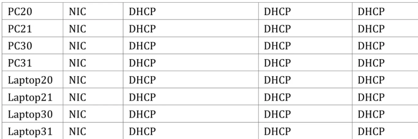
1.4Laptop20, Laptop21, PC20, PC21, Laptop30, Laptop31, PC30 y PC31
deben obtener información IPv4 del servidor DHCP. Laptop 20
Laptop 21
Pc20
Laptop 30
Laptop31
Pc30
1.5R1 debe realizar una NAT con sobrecarga sobre una dirección IPv4 pública. Asegúrese de que todos los terminales pueden comunicarse con Internet pública (haga ping a la dirección ISP) y la lista de acceso estándar se llama INSIDE-DEVS.
R1> enable R1# config t
Enter configuration commands, one per line. End with CNTL/Z.
R1(config)# ip nat pool NAT-POOL2 200.123.211.1 200.123.211.14 netmask 255.255.255.0
R1(config)# access-list 1 permit 192.168.0.0 0.0.255.255
R1(config)#ip nat inside source list 1 pool NAT-POOL2 overload R1(config)# interface serial0/0/0
R1(config-if)# ip nat inside
R1(config-if)# interface serial0/0/0 R1(config-if)# ip nat outside
R1(config-if)#%SYS-5-CONFIG_I: Configured from console by console
R1# show ip nat statistics
Total translations: 0 (0 static, 0 dynamic, 0 extended) Outside Interfaces: Serial0/0/0
Inside Interfaces: Hits: 0 Misses: 0 Expired translations: 0 Dynamic mappings: -- Inside Source
access-list 1 pool public_access refCount 0 pool public_access: netmask 255.255.255.224 start 200.123.210.4 end 200.123.210.10
type generic, total addresses 7 , allocated 0 (0%), misses 0
1.6R1 debe tener una ruta estática predeterminada al ISP que se configuró y que
incluye esa ruta en el dominio RIPv2.
10.0.0.0/30 via 200.123.211.1
R2 es un servidor de DHCP para los dispositivos conectados al puerto FastEthernet0/0.
R2(config)#ip dhcp pool desktops
R2(dhcp-config)#network 192.168.20.0 255.255.255.0 R2(dhcp-config)#default-router 192.168.20.1
R2(dhcp-config)#network 192.168.21.0 255.255.255.0 R2(dhcp-config)#default-router 192.168.20.1
R2(dhcp-config)# end
R2(config)# ip dhcp pool desktops
R2(dhcp-config)# network 192.168.30.0 255.255.255.0 R2(dhcp-config)# default-router 192.168.30.1
R2(dhcp-config)# end R2#
1.7R2 debe, además de enrutamiento a otras partes de la red, ruta entre las
VLAN 100 y 200.
R2(config)#int f0/0.100
R2(config-subif)# encapsulation dot1Q 100
R2(config-subif)#ip address 192.168.20.1 255.255.255.0 R2(config-subif)#int f0/0.200
R2(config-subif)# encapsulation dot1Q 200
R2(config-subif)#ip address 192.168.21.1 255.255.255.0 R2(config-subif)# exit
R2(config)# int f0/0
1.8El Servidor0 es sólo un servidor IPv6 y solo debe ser accesibles para los
dispositivos en R3 (ping).
R3(config)# ipv6 unicast-routing R3(config)# int f0/0
R3(config-if)#ipv6 address 200:db8:130::9c0:80F:301/64 R3(config-if)# exit
1.9La NIC instalado en direcciones IPv4 e IPv6 de Laptop30, de Laptop31, de PC30 y obligación de configurados PC31 simultáneas (dual-stack). Las direcciones se deben configurar mediante DHCP y DHCPv6.
Laptop 30 y 31
Pc30 y 31
1.10 La interfaz FastEthernet 0/0 del R3 también deben tener
R3(config)# ip dhcp pool desktops
R3(dhcp-config)#network 192.168.30.0 255.255.255.0 R3(dhcp-config)#default-router 192.168.30.1
R3(config)#ipv6 dhcp pool prueba
R3(config-dhcpv6)#prefix-delegation pool prueba R3(config-dhcpv6)# exit
R3(config)#ipv6 general-prefix prueba 2001:db8:130::9c0:80f:300/64 R3(config)#ipv6 local pool prueba 2001:db8:130::9c0:80f:310/40 64 R3(config)# interface f0/0
R3(config-if)#ipv6 dhcp server prueba R3(config-if)# end
R3#
1.11R1, R2 y R3 intercambian información de routing mediante RIP versión 2.
1.11.1 Configuración router rip
R1> enable R1# config t
Enter configuration commands, one per line. End with CNTL/Z. R1(config)# router rip
R1(config-router)# version 2
R1(config-router)#network 200.123.211.0 R1(config-router)#network 10.0.0.0 R1(config-router)#
R2# config t
Enter configuration commands, one per line. End with CNTL/Z. R2(config)# router rip
R2(config-router)# version 2
R2(config-router)# network 192.168.20.0 R2(config-router)# network 192.168.21.0 R2(config-router)# network 10.0.0.0 R2(config-router)#
R3> enable R3# confi t
Enter configuration commands, one per line. End with CNTL/Z. R3(config)# router rip
R3(config-router)# version 2
R3(config-router)# exit R3(config)#
R3# show ip route
Gateway of last resort is 10.0.0.5 to network 0.0.0.0
10.0.0.0/30 is subnetted, 3 subnets
R 10.0.0.0 [120/1] via 10.0.0.5, 00:00:15, Serial0/0/0 C 10.0.0.4 is directly connected, Serial0/0/0
C 10.0.0.8 is directly connected, Serial0/0/1
R 192.168.20.0/24 [120/2] via 10.0.0.5, 00:00:15, Serial0/0/0 R 192.168.21.0/24 [120/2] via 10.0.0.5, 00:00:15, Serial0/0/0 C 192.168.30.0/24 is directly connected, FastEthernet0/0 R 200.123.211.0/24 [120/1] via 10.0.0.5, 00:00:15, Serial0/0/0 R* 0.0.0.0/0 [120/1] via 10.0.0.5, 00:00:15, Serial0/0/0
R3#
1.12 R1, R2 y R3 deben saber sobre las rutas de cada uno y la ruta
predeterminada desde R1.
R1# show protocol Global values:
Internet Protocol routing is enabled
FastEthernet0/0 is administratively down, line protocol is down FastEthernet0/1 is administratively down, line protocol is down Serial0/0/0 is up, line protocol is up
Internet address is 200.123.211.2/24
Serial0/0/1 is administratively down, line protocol is down Serial0/1/0 is up, line protocol is up
Internet address is 10.0.0.1/30 Serial0/1/1 is up, line protocol is up Internet address is 10.0.0.5/30
Vlan1 is administratively down, line protocol is down
1.13 Verifique la conectividad. Todos los terminales deben poder hacer
Ping de la laptop30 a la pc 21 192.168.20.1 y al ISP 200.123.211.1
2.
Escenario 2
2.1. Configurar el direccionamiento IP acorde con la topología de red para cada uno de los dispositivos que forman parte del escenario
Realizamos la topología como se muestra en la figura
2.1.1 Configuración del direccionamiento ip de Internet PC
Seleccionamos la configuración IP estática y configuramos lo siguiente: IP address: 209.165.200.230
Mascara de subred: 255.255.255.248 Gateway predeterminado: 209.165.200.225
2.1.2 Configuración de Web Server
Seleccionamos la configuración IP estática y configuramos lo siguiente: IP address: 10.10.10.10
Mascara de subred: 255.255.255.0 Gateway predeterminado: 10.10.10.1
2.1.3 Configuración de R1
Router>enable
Router#configure terminal
Enter configuration commands, one per line. End with CNTL/Z. Router(config)#hostname R1
R1(config)#int s0/0/0
R1(config-if)#description connection to R2
R1(config-if)#clock rate 128000 R1(config-if)#no shutdown
%LINK-5-CHANGED: Interface Serial0/0/0, changed state to down R1(config-if)#
R1(config-if)#exit
R1(config)#ip route 0.0.0.0 0.0.0.0 s0/0/0 R1(config)#
2.1.4 Configuración del R2
Router>enable
Router#configure terminal
Enter configuration commands, one per line. End with CNTL/Z. Router(config)#hostname R2
R2(config)#int s0/0/1
R2(config-if)#descrip connection to R1
R2(config-if)#ip add 172.31.21.2 255.255.255.252 R2(config-if)#no shutdown
R2(config-if)#
%LINK-5-CHANGED: Interface Serial0/0/1, changed state to up
%LINEPROTO-5-UPDOWN: Line protocol on Interface Serial0/0/1, changed state to up
R2(config-if)#int s0/0/0
R2(config-if)#descrip connection to R3
R2(config-if)#ip add 172.31.23.1 255.255.255.252 R2(config-if)#clock rate 128000
R2(config-if)#no shutdown
%LINK-5-CHANGED: Interface Serial0/0/0, changed state to down R2(config-if)#int f0/0
R2(config-if)#descrip Internet PC
R2(config-if)#ip add 209.165.200.225 255.255.255.248 R2(config-if)#no shutdown
R2(config-if)#
%LINK-5-CHANGED: Interface FastEthernet0/0, changed state to up
%LINEPROTO-5-UPDOWN: Line protocol on Interface FastEthernet0/0, changed state to up
R2(config-if)#int f0/1
R2(config-if)#ip address 10.10.10.1 255.255.255.0 R2(config-if)#no shutdown
%LINK-5-CHANGED: Interface FastEthernet0/1, changed state to up
%LINEPROTO-5-UPDOWN: Line protocol on Interface FastEthernet0/1, changed state to up
R2(config-if)#description connection to web server R2(config-if)#exit
R2(config)#ip route 0.0.0.0 0.0.0.0 f0/0 R2(config)#
%LINK-5-CHANGED: Interface Serial0/0/0, changed state to up
%LINEPROTO-5-UPDOWN: Line protocol on Interface Serial0/0/0, changed state to up
2.1.5 Configuración del R3
Router>enable
Router#configure terminal
Enter configuration commands, one per line. End with CNTL/Z. Router(config)#hostname R3
R3(config)#int s0/0/1
R3(config-if)#description connection to R2
R3(config-if)#ip add 172.31.23.2 255.255.252.252 Bad mask 0xFFFFFCFC for address 172.31.23.2 R3(config-if)#ip add 172.31.23.2 255.255.255.252 R3(config-if)#no shutdown
R3(config-if)#
%LINK-5-CHANGED: Interface Serial0/0/1, changed state to up int l
%LINEPROTO-5-UPDOWN: Line protocol on Interface Serial0/0/1, changed state to up
^
% Invalid input detected at '^' marker. R3(config-if)#int lo4
R3(config-if)#
%LINK-5-CHANGED: Interface Loopback4, changed state to up
%LINEPROTO-5-UPDOWN: Line protocol on Interface Loopback4, changed state to up
R3(config-if)#ip address 192.168.4.1 255.255.255.0 R3(config-if)#no shutdown
R3(config-if)#
%LINK-5-CHANGED: Interface Loopback5, changed state to up
%LINEPROTO-5-UPDOWN: Line protocol on Interface Loopback5, changed state to up
R3(config-if)#ip add 192.168.5.1 255.255.255.0 R3(config-if)#no shutdown
R3(config-if)#int lo6
R3(config-if)#
%LINK-5-CHANGED: Interface Loopback6, changed state to up
%LINEPROTO-5-UPDOWN: Line protocol on Interface Loopback6, changed state to up
R3(config-if)#ip add 192.168.6.1 255.255.255.0 R3(config-if)#exit
R3(config)#ip route 0.0.0.0 0.0.0.0 s0/0/1 R3(config)#
2.1.6 Configuración de “S1”
Switch>enable
Switch#configure terminal
Enter configuration commands, one per line. End with CNTL/Z. Switch(config)#no ip domain-lookup
Switch(config)#hostname S1 S1(config)#exit
S1#
%SYS-5-CONFIG_I: Configured from console by console
2.1.7 Configuración de “S3”
Switch>enable
Switch#configure terminal
Enter configuration commands, one per line. End with CNTL/Z. Switch(config)#no ip domain-lookup
Switch(config)#hostname S3 S3(config)#exit
S3#
%SYS-5-CONFIG_I: Configured from console by console
2.1.8 Configuración del direccionamiento ip de “PC-A”
Seleccionamos la configuración IP por DHCP y nos queda de la siguiente manera: IP address: 169.254.139.60
2.1.9 Configuración del direccionamiento ip de “PC-C”
Seleccionamos la configuración IPpor DHCP y nos queda de la siguiente manera: IP address: 169.254.236.160
Mascara de subred: 255.255.0.0 Gateway predeterminado: 0.0.0.0
2.2 Configurar el protocolo de enrutamiento OSPFv2 bajo los siguientes criterios:
OSPFv2 area 0
Configuration Item or Task Specification
Router ID R1 1.1.1.1
Router ID R2 5.5.5.5
Router ID R3 8.8.8.8
Configurar todas las interfaces LAN como pasivas
Establecer el ancho de banda para enlaces seriales en 256 Kb/s Ajustar el costo en la métrica de S0/0 a 9500
2.2.1 Configuración en R1
R1>enable
R1#configure terminal
Enter configuration commands, one per line. End with CNTL/Z. R1(config)#router ospf 1
R1(config-router)#router-id 1.1.1.1
R1(config-router)#Reload or use "clear ip ospf process" command, for this to take effect
R1(config-router)#no router-id 1.1.1.1 R1(config-router)#router-id 1.1.1.1
R1(config-router)#Reload or use "clear ip ospf process" command, for this to take effect
R1(config-router)#network 172.31.21.0 0.0.0.3 area 0 R1(config-router)#network 192.168.30.0 0.0.0.255 area 0 R1(config-router)#network 192.168.40.0 0.0.0.255 area 0 R1(config-router)#network 192.168.200.0 0.0.0.255 area 0 R1(config-router)#passive-interface f0/0
R1(config-router)#exit R1(config)#int s0/0/0
2.2.2 Configuración en R2
R2>enable
R2#configure terminal
Enter configuration commands, one per line. End with CNTL/Z. R2(config)#router ospf 1
R2(config-router)#router-id 5.5.5.5
R2(config-router)#network 172.31.21.0 0.0.0.3 area 0 R2(config-router)#
02:12:01: %OSPF-5-ADJCHG: Process 1, Nbr 1.1.1.1 on Serial0/0/1 from LOADING to FULL, Loading Done
R2(config-router)#network 172.31.23.0 0.0.0.3 area 0 R2(config-router)#network 172.31.23.0 0.0.0.3 area 0 R2(config-router)#network 172.31.21.0 0.0.0.3 area 0 R2(config-router)#network 10.10.10.0 0.0.0.255 area 0 R2(config-router)#passive-interface f0/0 R2(config-router)#interface s0/0/0 R2(config-if)#bandwidth 256 R2(config-if)#interface s0/0/1 R2(config-if)#bandwidth 256 R2(config-if)#interface s0/0/0 R2(config-if)#ip ospf cost 9500
R2(config-if)#
2.2.3 Configuración en R3
R3>enable
R3#configure terminal
Enter configuration commands, one per line. End with CNTL/Z. R3(config)#router ospf 1
R3(config-router)#router-id 8.8.8.8
R3(config-router)#network 172.31.23.0 0.0.0.3 area 0 R3(config-router)#
02:25:30: %OSPF-5-ADJCHG: Process 1, Nbr 5.5.5.5 on Serial0/0/1 from LOADING to FULL, Loading Done
R3(config-router)#network 192.168.4.0 0.0.0.255 area 0 R3(config-router)#passive-interface lo4 R3(config-router)#passive-interface lo5 R3(config-router)#passive-interface lo6 R3(config-router)#exit R3(config)#int s0/0/1 R3(config-if)#bandwidth 256 R3(config-if)#ip ospf cost 9500
R3(config-if)#exit
Visualizar tablas de enrutamiento y routers conectados por OSPFv2
R2>enable
R2#show ip ospf neighbor
Neighbor ID Pri State Dead Time Address Interface 1.1.1.1 0 FULL/ - 00:00:30 172.31.21.1 Serial0/0/1
8.8.8.8 0 FULL/ - 00:00:39 172.31.23.2 Serial0/0/0
2.4 Visualizar lista resumida de interfaces por OSPF en donde se ilustre el costo
de cada interface
Para este paso se utiliza el comando show ip ospf interface brief pero este comando no es soportado por Packet tracert
R2#show ip ospf interface brief ^
% Invalid input detected at '^' marker.
2.5 Visualizar el OSPF Process ID, Router ID, Address summarizations, Routing
Networks, and passive interfaces configuradas en cada router.
R2#show ip protocols
Routing Protocol is "ospf 1"
Outgoing update filter list for all interfaces is not set Incoming update filter list for all interfaces is not set Router ID 5.5.5.5
Number of areas in this router is 1. 1 normal 0 stub 0 nssa Maximum path: 4
Routing for Networks: 172.31.21.0 0.0.0.3 area 0 172.31.23.0 0.0.0.3 area 0 10.10.10.0 0.0.0.255 area 0 Passive Interface(s): FastEthernet0/0
Routing Information Sources: Gateway Distance Last Update 1.1.1.1 110 00:28:05
2.6 Configurar VLANs, Puertos troncales, puertos de acceso, encapsulamiento, Inter-VLAN Routing y Seguridad en los Switches acorde a la topología de red establecida.
2.6.1 Se configuramos la seguridad en R1
R1>enable
R1#configure terminal
Enter configuration commands, one per line. End with CNTL/Z. R1(config)#enable secret class
R1(config)#line con 0 R1(config-line)#pass cisco R1(config-line)#login R1(config-line)#line vty 0 4 R1(config-line)#pass cisco R1(config-line)#login R1(config-line)#exit R1(config)#service pass
R1(config)#service password-encryption
R1(config)#banner motd #Prohibido El Acceso No Autorizado# R1(config)# exit
R1#copy running-config startup-config Destination filename [startup-config]? Building configuration...
[OK]
2.6.2 Seguridad en el router R2
R2>enable
R2#configure terminal
Enter configuration commands, one per line. End with CNTL/Z. R2(config)#enable secret class
R2(config)#line con 0 R2(config-line)#pass cisco R2(config-line)#login R2(config-line)#line vty 0 4 R2(config-line)#pass cisco R2(config-line)#login R2(config-line)#exit
R2(config)#service password-encryption
R2(config)#banner motd #Prohibido El Acceso No Autorizado# R2(config)#exit
R2#copy running-config startup-config Destination filename [startup-config]? Building configuration...
2.6.3 Configuración de seguridad en R3
R3>enable
R3#configure terminal
Enter configuration commands, one per line. End with CNTL/Z. R3(config)#enable secret class
R3(config)#line con 0 R3(config-line)#pass cisco R3(config-line)#login R3(config-line)#exit
R3(config)#service password-encryption
R3(config)#banner motd #Prohibido El Acceso No Autorizado# R3(config)#exit
R3#
%SYS-5-CONFIG_I: Configured from console by console
R3#copy running-config startup-config Destination filename [startup-config]? Building configuration...
[OK]
2.6.4 Configuración de seguridad en S1
S1>enable Password:
S1#configure terminal
Enter configuration commands, one per line. End with CNTL/Z. S1(config)#enable secret class
S1(config)#line con 0 S1(config-line)#pass cisco S1(config-line)#login S1(config-line)#line vty 0 4 S1(config-line)#pass cisco S1(config-line)#login
S1(config-line)#service password-encryption
S1(config)#banner motd #Prohibido El Acceso No Autorizado# S1(config)#exit
S1#
%SYS-5-CONFIG_I: Configured from console by console
S1#copy running-config startup-config Destination filename [startup-config]? Building configuration...
[OK]
2.6.5 Seguridad en S3
S3#configure terminal
Enter configuration commands, one per line. End with CNTL/Z. S3(config)#hostname S3
S3(config)#no ip domain-lookup S3(config)#enable secret class S3(config)#line con 0
S3(config-line)#pass cisco S3(config-line)#login S3(config-line)#line vty 0 4 S3(config-line)#pass cisco S3(config-line)#login S3(config-line)#exit
S3(config)#service password-encryption
S3(config)#banner motd #Prohibido El Acceso No Autorizado# S3(config)#exit
S3#
%SYS-5-CONFIG_I: Configured from console by console
2.6.6 Configuracion de vlan en S1
S1#configure terminal
Enter configuration commands, one per line. End with CNTL/Z. S1(config)#no ip domain-lookup
S1(config)#vlan 30 S1(config-vlan)#name Administracion S1(config-vlan)#vlan 40 S1(config-vlan)#name Mercadeo S1(config-vlan)#vlan 200 S1(config-vlan)#name Mantenimiento S1(config-vlan)#exit
S1(config)#int vlan 200 S1(config-if)#
%LINK-5-CHANGED: Interface Vlan200, changed state to up
S1(config-if)#ip address 192.168.200.2 255.255.255.0 S1(config-if)#no shut
S1(config-if)#exit
S1(config)#ip default-gateway 192.168.200.1 S1(config)#interface f0/3
S1(config-if)#switchport mode trunk
S1(config-if)#
%LINEPROTO-5-UPDOWN: Line protocol on Interface FastEthernet0/3, changed state to down
%LINEPROTO-5-UPDOWN: Line protocol on Interface FastEthernet0/3, changed state to up
S1(config-if)#switchport trunk native vlan 1 S1(config-if)#interface f0/24
S1(config-if)#switchport mode trunk
S1(config-if)#switchport trunk native vlan 1
S1(config-if)#interface range fa0/1-2, fa0/4-23, GigabitEthernet0/1-2 S1(config-if-range)#switchport mode access
S1(config-if-range)#interface fa0/1 S1(config-if)#switchport mode access S1(config-if)#switchport access vlan 30
S1(config-if)#interface range fa0/2, fa0/4-23, GigabitEthernet0/1-2 S1(config-if-range)#no shutdown
2.6.7 Configuración vlan en S3
Prohibido El Acceso No Autorizado
User Access Verification
Password:
S3>enable Password:
S3#configure terminal
Enter configuration commands, one per line. End with CNTL/Z. S3(config)#hostname S3
S3(config)#no ip domain-lookup S3(config)#vlan 30
S3(config-vlan)#name Administracion S3(config-vlan)#vlan 40
S3(config-vlan)#name Mercadeo S3(config-vlan)#vlan 200
S3(config-vlan)#name Mantenimiento S3(config-vlan)#exit
S3(config)#int vlan 200 S3(config-if)#
%LINK-5-CHANGED: Interface Vlan200, changed state to up
%LINEPROTO-5-UPDOWN: Line protocol on Interface Vlan200, changed state to up
S3(config-if)#ip address 192.168.200.3 255.255.255.0 S3(config-if)#no shutdown
S3(config-if)#exit
S3(config)#ip default-gateway 192.168.200.1 S3(config)#interface f0/3
S3(config-if)#switchport mode trunk
S3(config-if)#switchport trunk native vlan 1
S3(config-if-range)#switchport mode access S3(config-if-range)#interface fa0/1
S3(config-if)#switchport mode access S3(config-if)#switchport access vlan 40 S3(config-if)#
S3(config-if)#interface range fa0/2, fa0/4-24, GigabitEthernet0/1-2 S3(config-if-range)#shutdown
2.7 En el Switch 3 deshabilitar DNS lookup
S3#configure terminal
Enter configuration commands, one per line. End with CNTL/Z. S3(config)#no ip domain-lookup
S3(config)#exit S3#
%SYS-5-CONFIG_I: Configured from console by console
2.8 Asignar direcciones IP a los Switches acorde a los lineamientos.
2.8.1 Configuración de direcciones IP en S1
S1#configure terminal
Enter configuration commands, one per line. End with CNTL/Z. S1(config)#int vlan 200
S1(config-if)#ip address 192.168.200.2 255.255.255.0 S1(config-if)#no shutdown
S1(config-if)#exit
S1(config)#ip default-gateway 192.168.200.1
2.8.2 Configuración de direcciones IP en S3
Prohibido El Acceso No Autorizado
User Access Verification
Password:
S3>enable Password:
S3#configure terminal
Enter configuration commands, one per line. End with CNTL/Z. S3(config)#int vlan 200
S3(config-if)#ip address 192.168.200.3 255.255.255.0 S3(config-if)#no shutdown
S3(config)#ip default-gateway 192.168.200.1 S3(config)#
2.9 Desactivar todas las interfaces que no sean utilizadas en el esquema de red.
2.9.1 Desactivar interfaces en S1
S1#configure terminal
Enter configuration commands, one per line. End with CNTL/Z. S1(config)#
S1(config)#interface range fa0/1-2, fa0/4-23, GigabitEthernet0/1-2 S1(config-if-range)#switchport mode access
S1(config-if-range)#interface fa0/1 S1(config-if)#switchport mode access S1(config-if)#switchport access vlan 30
S1(config-if)#interface range fa0/2, fa0/4-23, GigabitEthernet0/1-2 S1(config-if-range)#shutdown
S1(config-if-range)#
2.9.2 Desactivar interfaces en S3
S3>enable Password:
S3#configure terminal
Enter configuration commands, one per line. End with CNTL/Z. S3(config)#int vlan 200
S3(config-if)#ip address 192.168.200.3 255.255.255.0 S3(config-if)#no shutdown
S3(config-if)#exit
S3(config)#ip default-gateway 192.168.200.1 S3(config)#
S3(config)#interface range fa0/1-2, fa0/4-24, GigabitEthernet0/1-2 S3(config-if-range)#switchport mode access
S3(config-if-range)#int fa0/1
S3(config-if)#switchport mode access S3(config-if)#switchport access vlan 40
S3(config-if)#interface range fa0/2, fa0/4-24, GigabitEthernet0/1-2 S3(config-if-range)#shutdown
2.10Implement DHCP and NAT for IPv4
Configuracion para R1
R1#configure terminal
Enter configuration commands, one per line. End with CNTL/Z. R1(config)#ip dhcp excluded-address 192.168.30.1 192.168.30.30 R1(config)#ip dhcp pool Administracion
R1(dhcp-config)#network 192.168.30.0 255.255.255.0 R1(dhcp-config)#default-router 192.168.30.1
R1(dhcp-config)#dns-server 10.10.10.11 R1(dhcp-config)#end
R1#
%SYS-5-CONFIG_I: Configured from console by console
R1#enable
R1#configure terminal
Enter configuration commands, one per line. End with CNTL/Z. R1(config)#ip dhcp excluded-address 192.168.40.1 192.168.40.30 R1(config)#ip dhcp pool Mercadeo
R1(dhcp-config)#network 192.168.40.0 255.255.255.0 R1(dhcp-config)#default-router 192.168.40.1
R1(dhcp-config)#dns-server 10.10.10.11 R1(dhcp-config)#end
R1#
%SYS-5-CONFIG_I: Configured from console by console
2.11
Configurar R1 como servidor DHCP para las VLANs 30 y 40.
R1#configure terminal
Enter configuration commands, one per line. End with CNTL/Z. R1(config)#ip dhcp excluded-address 192.168.30.1 192.168.30.30 R1(config)#ip dhcp excludded-address 192.168.40.1 192.168.40.30 ^
% Invalid input detected at '^' marker.
R1(config)#ip dhcp excluded-address 192.168.40.1 192.168.40.30 R1(config)#ip dchp pool Administracion
^
% Invalid input detected at '^' marker.
R1(config)#ip dhcp pool ADMINISTRACION R1(dhcp-config)#dns-server 10.10.10.11 R1(dhcp-config)#domain-name ccna-unad.com ^
% Invalid input detected at '^' marker.
R1(dhcp-config)#network 192.168.30.0 255.255.255.0 R1(dhcp-config)#exit
R1(config)#exit
2.12Reservar las primeras 30 direcciones IP de las VLAN 30 y 40 para
configuraciones estáticas.
Configurar DHCP pool para VLAN 30
Name: ADMINISTRACION DNS-Server: 10.10.10.11 Domain-Name: ccna-unad.com Establecer default gateway.
Configurar DHCP pool para VLAN 40
Name: MERCADEO DNS-Server: 10.10.10.11 Domain-Name: ccna-unad.com Establecer default gateway.
R1#configure terminal
Enter configuration commands, one per line. End with CNTL/Z. R1(config)#ip dhcp excluded-address 192.168.31.1 192.168.31.30 R1(config)#ip dhcp excluded-address 192.168.31.1 192.168.31.30 R1(config)#no ip dhcp excluded-address 192.168.31.1 192.168.31.30 R1(config)#ip dhcp excluded-address 192.168.30.1 192.168.30.30 R1(config)#ip dhcp excluded-address 192.168.40.1 192.168.40.30 R1(config)#ip dhcp pool Administracion
R1(dhcp-config)#dns-server 10.10.10.11 R1(dhcp-config)#domain-name ccna-unad.com ^
% Invalid input detected at '^' marker.
R1(dhcp-config)#default-router 192.168.30.1
R1(dhcp-config)#network 192.168.30.0 255.255.255.0 R1(dhcp-config)#ip dhcp pool Mercadeo
R1(dhcp-config)#dns-server 10.10.10.11 R1(dhcp-config)#domain-name ccna-unad.com ^
% Invalid input detected at '^' marker.
R1(dhcp-config)#default-router 192.168.40.1
R1(dhcp-config)#network 192.168.40.0 255.255.255.0
R1(dhcp-config)#
2.13Configurar NAT en R2 para permitir que los host puedan salir a internet
Enter configuration commands, one per line. End with CNTL/Z. R2(config)#access-list 1 permit 192.168.30.1 0.0.0.255
R2(config)#access-list 1 permit 192.168.40.1 0.0.0.255 R2(config)#no access-list 1 permit 192.168.30.1 0.0.0.255 R2(config)#no access-list 1 permit 192.168.40.1 0.0.0.255 R2(config)#access-list 1 permit 192.168.30.0 0.0.0.255 R2(config)#access-list 1 permit 192.168.40.0 0.0.0.255 R2(config)#access-list 1 permit 192.168.4.0 0.0.3.255
R2(config)#ip nat pool INTERNET 209.165.200.225 209.165.200.228 netmask 255.255.255.248
R2(config)#ip nat inside source list 1 pool INTERNET
R2(config)#ip nat inside source static 10.10.10.10 209.165.200.229
R2(config)#
2.14Configurar al menos dos listas de acceso de tipo estándar a su criterio en para
restringir o permitir tráfico desde R1 o R3 hacia R2.
R2#configure terminal
Enter configuration commands, one per line. End with CNTL/Z.
R2(config)#access-list 101 permit tcp any host 209.165.200.229 eq www R2(config)#access-list 101 permit icmp any any echo-reply
R2(config)#int f0/0
R2(config-if)#ip access-group 101 in R2(config-if)#int s0/0/1
R2(config-if)#ip access-group 101 out R2(config-if)#int s0/0/0
R2(config-if)#ip access-group 101 out R2(config-if)#int f0/1
R2(config-if)#ip access-group 101 out R2(config-if)#
2.15Configurar al menos dos listas de acceso de tipo extendido o nombradas a su
criterio en para restringir o permitir tráfico desde R1 o R3 hacia R2.
R2#configure terminal
Enter configuration commands, one per line. End with CNTL/Z. R2(config)#ip nat inside source static 10.10.10.10 209.165.200.229 R2(config)#int f0/0
R2(config-if)#ip nat outside R2(config-if)#int f0/1 R2(config-if)#ip nat inside R2(config-if)#end
%SYS-5-CONFIG_I: Configured from console by console
R2#configure terminal
Enter configuration commands, one per line. End with CNTL/Z. R2(config)#access-list 1 permit 192.168.30.0 0.0.0.255
R2(config)#access-list 1 permit 192.168.40.0 0.0.0.255 R2(config)#access-list 1 permit 192.168.4.0 0.0.3.255
R2(config)#ip nat pool INTERNET 209.165.200.225 209.165.200.228 netmask 255.255.255.248
R2(config)#ip nat inside source list 1 pool INTERNET R2(config)#
2.16Verificar procesos de comunicación y redireccionamiento de tráfico en los
routers mediante el uso de Ping y Traceroute.
Verificación con el comando ping
2.16.1 Ping de R1 a R2
2.16.2 Ping de R2 A R3
CONCLUSIONES
En el desarrollo del escenario uno me ayuda a poner en práctica el conocimiento
e investigar las diferentes formas de activar una red ya que nos ayuda a tener
comunicación entre varios computadoras, acortando distancia e implementando
seguridad en ella.
En el escenario se aplicó la configurar de VLAN, accesos troncal, DHCP,
RIPv2 y NAT con sobrecarga la cual ayuda a cambia varias IP privada en una
IP publica,
Escenario dos se logró la configuración de dirección IP protocolos de
enrutamiento OSPFv2 listas de acceso, creación y configuración de VLAN
BIBLIOGRAFÍA
Macfarlane, J. (2014). Network Routing Basics : Understanding IP Routing in Cisco Systems. Recuperado
de http://bibliotecavirtual.unad.edu.co:2048/login?url=http://search.ebscohost.c om/login.aspx?direct=true&db=e000xww&AN=158227&lang=es&site=ehost-live
Temática: Asignación de direcciones IP
CISCO. (2014). Asignación de direcciones IP. Fundamentos de Networking. Recuperado de
https://static-course-assets.s3.amazonaws.com/ITN50ES/module8/index.html#8.0.1.1
Temática: VLANs
CISCO. (2014). VLANs. Principios de Enrutamiento y Conmutación. Recuperado de
https://static-course-assets.s3.amazonaws.com/RSE50ES/module3/index.html#3.0.1.1
Temática: OSPF de una sola área
CISCO. (2014). OSPF de una sola área. Principios de Enrutamiento y Conmutación. Recuperado de
https://static-course-assets.s3.amazonaws.com/RSE50ES/module8/index.html#8.0.1.1
Temática: DHCP
CISCO. (2014). DHCP. Principios de Enrutamiento y Conmutación. Recuperado de