DIPLOMADO DE PROFUNDIZACION CISCO PRUEBA DE HABILIDADES PRÁCTICAS CCNP
ANDRÉS MAURICIO SERRANO QUENGUAN
UNIVERSIDAD NACIONAL ABIERTA Y A DISTANCIA - UNAD ESCUELA DE CIENCIAS BÁSICAS, TECNOLOGÍA E INGENIERÍA - ECBTI INGENIERÍA
DIPLOMADO DE PROFUNDIZACION CISCO PRUEBA DE HABILIDADES PRÁCTICAS CCNP
ANDRÉS MAURICIO SERRANO QUENGUAN
Diplomado de opción de grado presentado para optar el título INGENIERO ELECTRÓNICO
DIRECTOR:
MSc. GERARDO GRANADOS ACUÑA
UNIVERSIDAD NACIONAL ABIERTA Y A DISTANCIA - UNAD ESCUELA DE CIENCIAS BÁSICAS, TECNOLOGÍA E INGENIERÍA - ECBTI INGENIERÍA
NOTA DE ACEPTACIÓN
_________________________________________ _________________________________________ _________________________________________ _________________________________________ _________________________________________
_________________________________________ Firma del presidente del jurado
_________________________________________ Firma del jurado
________________________________________ Firma del jurado
4
AGRADECIMIENTOS
5
CONTENIDO
AGRADECIMIENTOS 04
CONTENIDO 05
LISTA DE TABLAS 06
LISTA DE FIGURAS 07
RESUMEN 09
ABSTRACT 10
INTRODUCCIÓN 11
DESARROLLO 12
1 Escenario 1 12
2 Escenario 2 23
3 Escenario 3 29
CONCLUSIONES 46
6
LISTA DE TABLAS
Tabla 1. Configuración Loopback en R1. 17
Tabla 2. Direccionamiento Loopback en R5. 19
Tabla 3. Configuración R1. 24
Tabla 4. Configuración R2. 24
Tabla 5. Configuración R3. 24
Tabla 6. Configuración R4. 24
Tabla 7. Direcciones de VLAN. 37
7
LISTA DE FIGURAS
Figura 1. Escenario 1. 12
Figura 2. Simulación Escenario 1. 12
Figura 3. Enrutamiento R3. 20
Figura 4. Enrutamiento mediante SHOW IP ROUTE en R1. 22 Figura 5. Enrutamiento mediante SHOW IP ROUTE en R5. 22
Figura 6. Escenario 2. 23
Figura 7. Simulación Escenario 2. 23
Figura 8. Comando SHOW IP BGP y SHOW IP ROUTE en AS1. 25
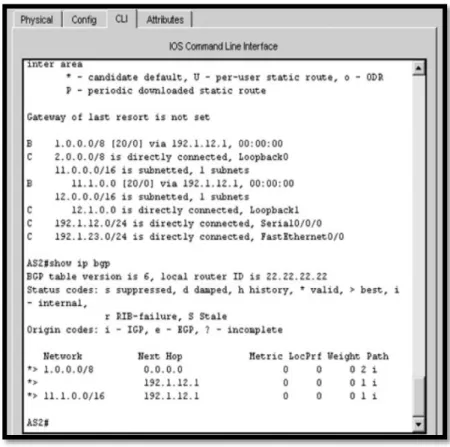
Figura 9. Comando SHOW IP BGP en AS2. 26
Figura 10. Comando SHOW IP ROUTE y SHOW IP BGP en AS3. 27 Figura 11. Comando SHOW IP ROUTE y SHOW IP BGP en AS4. 28
Figura 12. Escenario 3. 29
Figura 13. Simulación Escenario 3. 29
Figura 14. Configuración VTP SWITCH 1. 31
Figura 15. Configuración VTP SWITCH 2. 32
Figura 16. Configuración VTP SWITCH 3. 32
Figura 17. Enlace Trunk entre SWTICH1 con comando SHOW
INTERFACE TRUNK. 33
Figura 18. Enlace Trunk entre SWTICH2 con comando SHOW
INTERFACE TRUNK. 34
Figura 19. Enlace Trunk con comando SHOW INTERFACE
TRUNK en SWITCH1. 35
Figura 20. VLAN10 en SWITCH1. 36
Figura 21. VLAN 10 20 30 99 en SWITCH2. 37
Figura 22. Conectividad Extremo a Extremo. 43
8
Figura 24. Ping SWITCH 2 a SWITCH 1 SWITCH 3. 44
Figura 25. Ping SWITCH 3 a SWITCH 1 SWITCH 2. 44
Figura 26. Ping SWITCH 3. 45
9
RESUMEN
La prueba de habilidades prácticas para el curso DIPLOMADO DE
PROFUNDIZACIÓN CISCO CCNP, se realiza para abordar y conocer los temas de importancia que conforman el curso como forma de aprendizaje acerca del proceso de enrutamiento y configuración avanzado usando equipos activos en la conformación de redes como switches, router y otros elementos que conforman una red; segmentándola usando las VLAN para enviar paquetes por la red de destino a través de equipos conectados transportando el tráfico por capa dos y capa tres respectivamente ocupando protocolos como: IP, OSPF, usando rutas estáticas y evidenciando adyacencias convergentes en la red. También se desarrollan temas que forman parte del módulo CCNP ROUTE R&S y al módulo CCNP SWITCH R&S. En el presente trabajo abordaremos dos
escenarios en los cuales demostraremos las habilidades para desarrollar la configuración y administración de dispositivos de Networking orientados al diseño de redes escalables y de conmutación, cuyos conocimientos fueron obtenidos en el transcurso del curso de profundización. Se utilizará además para la simulación en software Packet Tracer.
Palabras Clave:
10
ABSTRACT
The test of practical skills for the CISCO CCNP DIPLOMA DEPTHENING course, is made to approach and to know the important subjects that conform the course as form of learning about the process of routing and advanced configuration using active equipment in the conformation of networks like switches, router and other elements that conform a network; segmenting it using the VLANs to send
packages by the destiny network through connected equipment transporting the traffic by layer two and layer three respectively occupying protocols like IP, OSPF, using static routes and evidencing converged adjacencies in the network. We also develop topics that are part of the CCNP ROUTE R&S module and the CCNP SWITCH R&S module. In this paper we will address two scenarios in which we will demonstrate the skills to develop the configuration and management of networking devices oriented to the design of scalable and switching networks, whose
knowledge was obtained during the course of the in-depth course. It will also be used for simulation in Packet Tracer software.
Keywords:
11
INTRODUCCIÓN
El CCNP (Cisco Certified NetWork Professional) es la certificación profesional de Cisco System ubicada en el centro de la pirámide que representa las
certificaciones de este gigante de las comunicaciones. El CCNA (Cisco Certified NetWork Associate) es la base y la escala inicial de las certificaciones de redes Cisco y el CCIE (Cisco Certified Intemetwork Expert) es la cima a la que todo profesional de las redes quisiera llegar.
A continuación, se desarrolla el trabajo en base a la prueba de habilidades prácticas para el curso DIPLOMADO DE PROFUNDIZACIÓN CISCO CCNP y a través de la cual se pondrá a prueba los niveles de comprensión y solución de problemas relacionados con diversos aspectos de Networking. Donde a través de los conocimientos adquiridos desde entorno de conocimiento que nos proporciona el curso, como la investigación individual se pudo consolidar el producto final, esto con el fin de planificar, implementar, verificar y solucionar problemas de redes empresariales locales y de área amplia. El curso de profundización CCNP, busca que los Profesionales indaguen en este campo emergente de las Redes y
12
DESARROLLO
1. Escenario 1
Figura 1. Escenario 1.
13
1.1. Aplique las configuraciones iniciales y los protocolos de enrutamiento para los routers R1, R2, R3, R4 y R5 según el diagrama. No asigne passwords en los routers. Configurar las interfaces con las direcciones que se
muestran en la topología de red.
Se procede a configurar cada uno de los enrutadores. 1, 2, 3, 4, 5
Se asignan nombre y protocolos de comunicación mediante EIGRP que fueron asignados.
Router 1:
Router> Ingreso a modo privilegiado
Router>enable Ingreso a modo de configuración
Router#configure terminal Enter configuration commands, one per line. End with CNTL/Z.
Router(config)#hostname R1 Asigno nombre al router R1(config)#no ip domain-lookup
R1(config)#line con 0
R1(config-line)# logging synchronous R1(config-line)# exec-timeout 0 0 R1(config-line)#exit
R1(config)# interface loopback 1
%LINK-5-CHANGED: Interface Loopback1, changed state to up
%LINEPROTO-5-UPDOWN: Line protocol on Interface Loopback1, changed state to up
R1(config-if)#interface serial 0/0/1 Configuración de interfaz serial 1 R1(config-if)#ip address 10.103.12.2 255.255.255.0
R1(config-if)#clock rate 128000 Configuración del reloj R1(config-if)#no shutdown Interfaz activa
%LINK-5-CHANGED: Interface Serial0/0/1, changed state to down R1(config-if)#exit
14
Router 2: Router>
Router>enable
Router#configure terminal Router(config)#hostname R2 R2(config)#no ip domain-lookup R2(config)#line con 0
R2(config-line)# logging synchronous R2(config-line)# exec-timeout 0 0 R2(config-line)#exit
R2(config)# interface loopback 2
%LINK-5-CHANGED: Interface Loopback2, changed state to up
%LINEPROTO-5-UPDOWN: Line protocol on Interface Loopback2, changed state to up
R2(config-if)#interface serial 0/0/0
R2(config-if)#ip address 10.103.12.1 255.255.255.0 R2(config-if)#no shutdown
%LINK-5-CHANGED: Interface Serial0/0/0, changed state to down R2(config-if)#interface serial 0/0/1
R2(config-if)#ip address 10.103.23.2 255.255.255.0 R2(config-if)#no shutdown
R2(config-if)#exit R2(config)#exit
Router#configure terminal R2(config)#router ospf 1
R2(config-router)#router-id 2.2.2.2
R2(config-router)#network 10.103.12.0 0.0.0.255 area 0 R2(config-router)#network 10.103.23.0 0.0.0.255 area 0 R2(config-if)#exit
15
Router 3: Router>
Router>enable
Router#configure terminal Router(config)#hostname R3 R3(config)#no ip domain-lookup R3(config)#line con 0
R3(config-line)# logging synchronous R3(config-line)# exec-timeout 0 0 R3(config-line)#exit
R3(config)# interface loopback 3
%LINK-5-CHANGED: Interface Loopback3, changed state to up
%LINEPROTO-5-UPDOWN: Line protocol on Interface Loopback3, changed state to up
R3(config-if)#interface serial 0/0/0
R3(config-if)#ip address 10.103.23.1 255.255.255.0 R3(config-if)#clock rate 128000
R3(config-if)#no shutdown R3(config-if)#exit
%LINEPROTO-5-UPDOWN:Line protocol on Int Serial0/0/0, changed state to up R3(config)#exit
R3(config)# interface loopback 3 R3(config-if)#interface serial 0/0/1
R3(config-if)#ip address 172.29.34.2 255.255.255.0 R3(config-if)#no shutdown
%LINK-5-CHANGED: Interface Serial0/0/1, changed state to down R3(config-if)#exit
16 Router 4: Router> Router>enable Router#configure terminal Router(config)#hostname R4 R4(config)#no ip domain-lookup R4(config)#line con 0
R4(config-line)# logging synchronous R4(config-line)# exec-timeout 0 0 R4(config-line)#exit
R4(config)# interface loopback 4
%LINK-5-CHANGED: Interface Loopback4, changed state to up
%LINEPROTO-5-UPDOWN: Line protocol on Interface Loopback4, changed state to up
R4(config-if)#interface serial 0/0/0
R4(config-if)#ip address 172.29.34.1 255.255.255.0 R4(config-if)#no shutdown
R4(config-if)#interface serial 0/0/1
R4(config-if)#ip address 172.29.45.2 255.255.255.0 R4(config-if)#no shutdown
%LINK-5-CHANGED: Interface Serial0/0/1, changed state to down R4(config-if)#exit
%LINK-5-CHANGED: Interface Serial0/0/0, changed state to up R4(config)#exit Router 5: Router> Router>enable Router#configure terminal Router(config)#hostname R5 R5(config)#no ip domain-lookup R5(config)#line con 0
R5(config-line)# logging synchronous R5(config-line)# exec-timeout 0 0 R5(config-line)#exit
R5(config)# interface loopback 5
%LINK-5-CHANGED: Interface Loopback5, changed state to up
%LINEPROTO-5-UPDOWN: Line protocol on Interface Loopback5, changed state to up
17
R5(config-if)#ip address 172.29.45.1 255.255.255.0 R5(config-if)#clock rate 128000
R5(config-if)#no shutdown R5(config-if)#exit
%LINK-5-CHANGED: Interface Serial0/0/0, changed state to up R5(config)#exit
1.2. Cree cuatro nuevas interfaces de Loopback en R1 utilizando la
asignación de direcciones 10.1.0.0/22 y configure esas interfaces para participar en el área 0 de OSPF.
Loopback en Router 1
Interface Loopback11 10.1.0.0/22 255.255.252.0 Interface Loopback12 10.1.4.1/22 255.255.252.0 Interface Loopback13 10.1.8.1/22 255.255.252.0 Interface Loopback14 10.1.12.1/22 255.255.252.0
Tabla 1. Configuración Loopback en R1.
CONFIGURACIÓN DE LOOPBACK EN R1. Router>
Router>enable
Router#configure terminal
Router(config)#interface loopback11
Router(config-if)#
%LINK-5-CHANGED: Interface Loopback11, changed state to up
%LINEPROTO-5-UPDOWN:Line protocol on Interface Loopback11, changed state to up
Router(config-if)#ip address 10.1.0.1 255.255.252.0 Router(config-if)#exit
Router(config)#interface loopback12 Router(config-if)#
%LINK-5-CHANGED: Interface Loopback12, changed state to up %LINEPROTO-5-UPDOWN: Line protocol on Interface Loopback12, changed state to up
Router(config-if)#ip address 10.1.4.1 255.255.252.0 Router(config-if)#exit
Router(config)#interface loopback13 Router(config-if)#
18
%LINEPROTO-5-UPDOWN: Line protocol on Interface Loopback13, changed state to up
Router(config-if)#ip address 10.1.8.1 255.255.252.0 Router(config-if)#exit
Router(config)#interface loopback14 Router(config-if)#
%LINK-5-CHANGED: Interface Loopback14, changed state to up %LINEPROTO-5-UPDOWN: Line protocol on Interface Loopback14, changed state to up
Router(config-if)#ip address 10.1.12.1 255.255.252.0 Router(config-if)#exit
Router(config)#router ospf 1
Router(config-router)#router-id 1.1.1.1
Router(config-router)#network 10.1.0.0 0.0.3.255 area 0 Router(config-router)#network 10.103.12.0
Router#
%SYS-5-CONFIG_I: Configured from console by console Router#configure terminal
Router(config)#router ospf 1
Router(config-router)#network 10.103.12.0 0.0.0.255 area 0 Router(config-router)#exit
Router(config)#exit Router#
Router#configure terminal
Router(config)#interface loopback11
Router(config-if)#ip ospf network point-to-point Router(config-if)#exit
Router(config)#interface loopback12
Router(config-if)#ip ospf network point-to-point Router(config-if)#exit
Router(config)#interface loopback13
Router(config-if)#ip ospf network point-to-point Router(config-if)#exit
Router(config)#interface loopback14
Router(config-if)#ip ospf network point-to-point Router(config-if)#exit
19
1.3. Cree cuatro nuevas interfaces de Loopback en R5 utilizando la
asignación 22 de direcciones 172.5.0.0/22 y configure esas interfaces para participar en el Sistema Autónomo EIGRP 10.
Loopback en Router 5
Interface Loopback51 172.5.0.1 255.255.252.0 Interface Loopback52 172.5.4.1 255.255.252.0 Interface Loopback53 172.5.8.1 255.255.252.0 Interface Loopback54 172.5.12.1 255.255.252.0
Tabla 2. Direccionamiento Loopback en R5.
CONFIGURACIÓN DE LOOPBACK EN R5. Router>enable
Router#configure terminal
Router(config)#interface loopback51 Router(config-if)#
%LINK-5-CHANGED: Interface Loopback51, changed state to up
%LINEPROTO-5-UPDOWN: Line protocol on Interface Loopback51, changed state to up
Router(config-if)#ip address 172.5.0.1 255.255.252.0 Router(config-if)#exit
Router(config)#interface loopback52 Router(config-if)#
%LINK-5-CHANGED: Interface Loopback52, changed state to up
%LINEPROTO-5-UPDOWN: Line protocol on Interface Loopback52, changed state to up
Router(config-if)#ip address 172.5.4.1 255.255.252.0 Router(config-if)#exit
Router(config)#interface loopback53 Router(config-if)#
%LINK-5-CHANGED: Interface Loopback53, changed state to up
%LINEPROTO-5-UPDOWN: Line protocol on Interface Loopback53, changed state to up
Router(config-if)#ip address 172.5.8.1 255.255.252.0 Router(config-if)#exit
Router(config)#interface loopback54 Router(config-if)#
%LINK-5-CHANGED: Interface Loopback54, changed state to up
%LINEPROTO-5-UPDOWN: Line protocol on Interface Loopback54, changed state to up
20
Router(config-if)#exit Router(config)#
Router(config)#route eigrp 10
Router(config-router)#auto-summary
Router(config-router)#network 172.5.0.0 0.0.3.255 Router(config-router)#network 172.29.45.0 0.0.0.255
1.4. Analice la tabla de enrutamiento de R3 y verifique que R3 está
aprendiendo las nuevas interfaces de Loopback mediante el comando show ip route.
Figura 3. Enrutamiento R3.
1.5. Configure R3 para redistribuir las rutas EIGRP en OSPF usando el costo de 50000 y luego redistribuya las rutas OSPF en EIGRP usando un ancho de banda T1 y 20,000 microsegundos de retardo.
Router>enable
Router#configure terminal Enter configuration commands, one per line. End with CNTL/Z.
Router(config)#router ospf 10
21
Router(config-router)#exit Router(config)#router ospf 1
Router(config-router)#redistribute eigrp 10 % Only classful networks will be redistributed Router(config-router)#redistribute eigrp 10 subnets Router(config-router)#exit
Router(config)#router eigrp 10
Router(config-router)#redistribute ospf 1 metric 1544 100 255 1 1500 Router(config-router)#exit
Router(config)#exit
%SYS-5-CONFIG_I: Configured from console by console Router#show ip route Codes: C - connected, S - static, I - IGRP, R - RIP, M - mobile, B - BGP D - EIGRP, EX - EIGRP external, O - OSPF, IA - OSPF inter area N1 - OSPF NSSA external type 1, N2 - OSPF NSSA external type 2 E1 - OSPF external type 1, E2 - OSPF external type 2, E - EGP i - IS-IS, L1 - IS-IS level-1, L2 - IS-IS level-2, ia - IS-IS inter area - candidate default, U - per-user static route, o - ODR P - periodic downloaded static route Gateway of last resort is not set
10.0.0.0/8 is variably subnetted, 3 subnets, 2 masks O 10.1.0.0/22 [110/129] via 10.103.23.2, 00:08:56, Serial0/0/0 O 10.103.12.0/24 [110/128] via 10.103.23.2, 00:08:56, Serial0/0/0 C 10.103.23.0/24 is directly connected, Serial0/0/0
172.29.0.0/24 is subnetted, 1 subnets C 172.29.34.0 is directly connected, Serial0/0/1
Router#show ip route
Codes: C - connected, S - static, I - IGRP, R - RIP, M - mobile, B - BGP D - EIGRP, EX - EIGRP external, O - OSPF, IA - OSPF inter area N1 - OSPF NSSA external type 1, N2 - OSPF NSSA external type 2 E1 - OSPF external type 1, E2 - OSPF external type 2, E - EGP i - IS-IS, L1 - IS-IS level-1, L2 - IS-IS level-2, ia - IS-IS inter area - candidate default, U - per-user static route, o - ODR P - periodic downloaded static route Gateway of last resort is not set
10.0.0.0/8 is variably subnetted, 3 subnets, 2 masks O 10.1.0.0/22 [110/129] via 10.103.23.2, 00:10:57, Serial0/0/0 O 10.103.12.0/24 [110/128] via 10.103.23.2, 00:10:57, Serial0/0/0 C 10.103.23.0/24 is directly connected, Serial0/0/0
172.29.0.0/24 is subnetted, 1 subnets C 172.29.34.0 is directly connected, Serial0/0/1
Router#configure
Router(config)#router ospf 1
Router(config-router)#redistribute eigrp 10 subnets Router(config-router)#log-adjacency-changes Router(config-router)#redistribute eigrp 7 subnets
Router(config-router)#network 172.29.45.0 0.0.0.255 area 0 Router(config-router)#exit
Router(config)#router eigrp 10
Router(config-router)#redistribute ospf 1 metric 50000 200 255 1 1500 Router(config-router)#auto-summary
22
1.6. Verifique en R1 y R5 que las rutas del sistema autónomo opuesto existen en su tabla de enrutamiento mediante el comando show ip route.
Figura 4. Enrutamiento mediante SHOW IP ROUTE en R1.
23
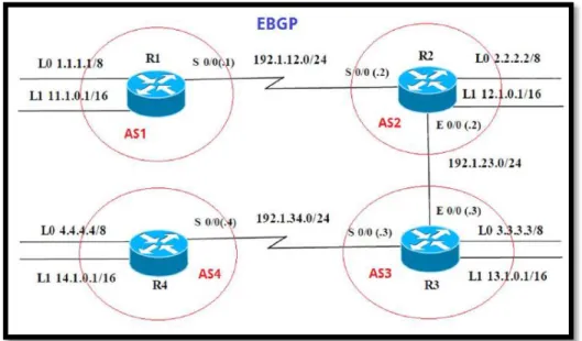
2. ESCENARIO 2
Figura 6. Escenario 2.
24
2.1. Información para configuración de los Routers
En la siguiente fase aplicaremos la configuración a los router con la
información que fueron asignadas por tablas, se crean las Loopback. (R1)
INTERFAZ DIRECCIÓN IP MÁSCARA
Loopback 0 1.1.1.1 255.0.0.0
Loopback 1 11.1.0.1 255.255.0.0
S 0/0 192.1.12.1 255.255.255.0
Tabla 3. Configuración R1.
INTERFAZ DIRECCIÓN IP MÁSCARA
Loopback 0 2.2.2.2 255.0.0.0
Loopback 1 12.1.0.1 255.255.0.0
S 0/0 192.1.12.1 255.255.255.0
E 0/0 192.1.23.2 255.255.255.0
Tabla 4. Configuración R2.
INTERFAZ DIRECCIÓN IP MÁSCARA
Loopback 0 3.3.3.3 255.0.0.0
Loopback 1 13.1.0.1 255.255.0.0
S 0/0 192.1.23.3 255.255.255.0
E 0/0 192.1.34.3 255.255.255.0
Tabla 5. Configuración R3.
INTERFAZ DIRECCIÓN IP MÁSCARA
Loopback 0 4.4.4.4 255.0.0.0
Loopback 1 14.1.0.1 255.255.0.0
S 0/0 192.1.34.4 255.255.255.0
25
2.2. Configure una relación de vecino BGP entre R1 y R2. R1 debe estar en AS1 y R2 debe estar en AS2. Anuncie las direcciones de Loopback en BGP. Codifique los ID para los Routers BGP como 11.11.11.11 para R1 y como 22.22.22.22 para R2. Presente el paso a con los comandos utilizados y la salida del comando show ip route.
AS1#enable
AS1#configure terminal
Enter configuration commands, one per line. End with CNTL/Z. AS1(config)#router bgp 1
AS1(config-router)#exit AS1(config)#no router bgp 1 AS1(config)#router bgp 1
AS1(config-router)#bgp router-id 11.11.11.11
AS1(config-router)#neighbor 192.1.12.2 remote-as 2 AS1(config-router)#network 1.1.1.1 mask 255.0.0.0 AS1(config-router)#network 11.1.0.1 mask 255.255.0.0 AS1(config-router)#exit
AS1(config)#exit
26
AS2>enable
AS2#configure terminal Enter configuration commands, one per line. End with CNTL/Z.
AS2(config)#router bgp 2
AS2(config-router)#bgp router-id 22.22.22.22
AS2(config-router)#neighbor 192.1.12.1 remote-as 1 AS2(config-router)#neighbor 192.1.34.3 remote-as 3 AS2(config-router)#neighbor 192.1.23.3 remote-as 3
AS2(config-router)#%BGP-5-ADJCHANGE: neighbor 192.1.12.1 Up AS2(config-router)#network 1.1.1.0
AS2(config-router)#network 11.1.0.0 AS2(config-router)#exit
AS2(config)#exit
27
2.3. Configure una relación de vecino BGP entre R2 y R3. R2 ya debería estar configurado en AS2 y R3 debería estar en AS3. Anuncie las direcciones de Loopback de R3 en BGP. Codifique el ID del router R3 como 33.33.33.33. Presente el paso a con los comandos utilizados y la salida del comando show ip route.
AS3>enable
AS3#configure terminal Enter configuration commands, one per line. End with CNTL/Z.
AS3(config)#router bgp 3
AS3(config-router)#neighbor 192.1.12.2 remote-as 2 AS3(config-router)#neighbor 192.1.23.2 remote-as 2 AS3#%BGP-5-ADJCHANGE: neighbor 192.1.23.2 Up AS3(config-router)#neighbor 192.1.34.4 remote-as 4 AS3(config-router)#network 4.4.4.4 mask 255.0.0.0 AS3(config-router)#network 14.1.0.1 mask 255.255.0.0 AS3(config-router)#network 2.2.2.2 mask 255.0.0.0 AS3(config-router)#network 12.1.0.1 mask 255.255.0.0 AS3(config-router)#network 3.3.3.3 mask 255.0.0.0 AS3(config-router)#network 13.1.0.1 mask 255.255.0.0 AS3(config-router)#exit
28
2.4. Configure una relación de vecino BGP entre R3 y R4. R3 ya debería estar configurado en AS3 y R4 debería estar en AS4. Anuncie las direcciones de Loopback de R4 en BGP. Codifique el ID del router R4 como 44.44.44.44. Establezca las relaciones de vecino con base en las direcciones de Loopback 0. Cree rutas estáticas para alcanzar la Loopback 0 del otro router. No anuncie la Loopback 0 en BGP. Anuncie la red Loopback de R4 en BGP. Presente el paso a con los comandos utilizados y la salida del comando show ip route.
AS4>enable
AS4#configure terminal Enter configuration commands, one per line. End with CNTL/Z. AS4(config)#router bgp 4
AS4(config-router)#neighbor 192.1.34.3 remote-as 3
AS4(config-router)#%BGP-5-ADJCHANGE: neighbor 192.1.34.3 Up AS4(config-router)#neighbor 192.1.23.3 remote-as 3
AS4(config-router)#%BGP-5-ADJCHANGE: neighbor 192.1.23.3 Up AS4(config-router)#neighbor 192.1.23.2 remote-as 2
AS4(config-router)#neighbor 192.1.12.2 remote-as 2 AS4(config-router)#neighbor 192.1.12.1 remote-as 1
AS4(config-router)#%BGP-5-ADJCHANGE: neighbor 192.1.34.3 Up AS4(config-router)#network 3.3.3.3 mask 255.0.0.0
AS4(config-router)#network 13.1.0.1 mask255.255.0.0 AS4(config-router)#network 12.1.0.1 mask255.255.0.0 AS4(config-router)#network 2.2.2.2 mask 255.0.0.0 AS4(config-router)#network 11.1.0.1 mask 255.255.0.0 AS4(config-router)#network 4.4.4.4 mask 255.0.0.0 AS4(config-router)#network 14.1.0.1 mask 255.255.0.0 AS4(config-router)#exit
AS4(config)#exit
29
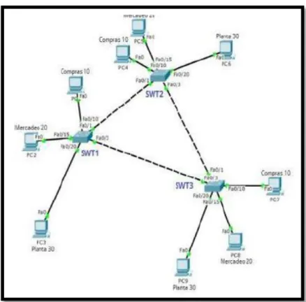
3. ESCENARIO 3
Figura 12. Escenario 3.
30
3.1. Todos los switches se configurarán para usar VTP para las
actualizaciones de VLAN. El Switch SWT2 se configurará como el servidor. Los switches SWT1 y SWT3 se configurarán como clientes. Los switches estarán en el dominio VPT llamado CCNP y usando la contraseña cisco. Se procede a realizar configuración VTP (dominio, versión y modo) en cada Switch. Estableciendo como servidor el Switch 2, los switches 1 y 3 se encontraran en modo cliente.
CONFIGURACIÓN VTP SWITCH 1 Switch>enable
Switch#configure terminal Enter configuration commands, one per line. End with CNTL/Z.
Switch(config)#hostname SWT1 SWT1(config)#vtp domain CCNP
Changing VTP domain name from NULL to CCNP SWT1(config)#vtp version 2
SWT1(config)#vtp mode client
Setting device to VTP CLIENT mode. SWT1(config)#vtp password cisco
Setting device VLAN database password to cisco SWT1(config)#
CONFIGURACIÓN VTP SWITCH 2 Switch>enable
Switch#configure terminal Enter configuration commands, one per line. End with CNTL/Z.
Switch(config)#hostname SWT2 SWT2(config)#vtp domain CCNP
Changing VTP domain name from NULL to CCNP SWT2(config)#vtp version 2
SWT2(config)#vtp mode server Device mode already VTP SERVER. SWT2(config)#vtp password cisco
31
CONFIGURACIÓN VTP SWITCH 3 Switch>enable
Switch#configure terminal Enter configuration commands, one per line. End with CNTL/Z.
Switch(config)#hostname SWT3 SWT3(config)#vtp domain CCNP
Changing VTP domain name from NULL to CCNP SWT3(config)#vtp version 2
SWT3(config)#vtp mode client
Setting device to VTP CLIENT mode. SWT3(config)#vtp password cisco
Setting device VLAN database password to cisco SWT3(config)#
3.2. Verifique las configuraciones mediante el comando show vtp status.
32
Figura 15. Configuración VTP SWITCH 2.
33
3.3.
Configurar DTP (Dynamic Trunking Protocol)
3.3.1. Configure un enlace troncal ("trunk") dinámico entre SWT1y SWT2. Debido a que el modo por defecto es dynamic auto, solo un lado del enlace debe configurarse como dynamic desirable.
SWT1>enable
SWT1#configure terminal Enter configuration commands, one per line. End with CNTL/Z.
SWT1(config)#interface fastEthernet 0/1
SWT1(config-if)#switchport mode dynamic desirable SWT1(config-if)#
%LINEPROTO-5-UPDOWN: Line protocol on Interface FastEthernet0/1, changed state to up
%LINEPROTO-5-UPDOWN: Line protocol on Interface FastEthernet0/1, changed state to down
%LINEPROTO-5-UPDOWN: Line protocol on Interface FastEthernet0/1, changed state to up
3.3.2. Verifique el enlace "trunk" entre SWT1 y SWT2 usando el comando show interfaces trunk.
34
Figura 18. Enlace Trunk entre SWTICH2 con comando SHOW INTERFACE TRUNK.
3.3.3. Entre SWT1 y SWT3 configure un enlace "trunk" estático utilizando el comando switchport mode trunk en la interfaz F0/3 de SWT1
SWT1>enable
SWT1#configure terminal Enter configuration commands, one per line. End with CNTL/Z.
SWT1(config)#interface fastEthernet 0/3 SWT1(config-if)#switchport mode trunk SWT1(config-if)#
%LINEPROTO-5-UPDOWN: Line protocol on Interface FastEthernet0/3, changed state to down
35
Figura 19. Enlace Trunk con comando SHOW INTERFACE TRUNK en SWITCH1.
3.3.4. Configure un enlace "trunk" permanente entre SWT2 y SWT3.
CONFIGURACIÓN SWITCH 2 SWT2>enable
SWT2#configure terminal Enter configuration commands, one per line. End with CNTL/Z.
SWT2(config)#interface fastEthernet 0/3 SWT2(config-if)#switchport mode trunk SWT2(config-if)#
%LINEPROTO-5-UPDOWN: Line protocol on Interface FastEthernet0/3, changed state to down
%LINEPROTO-5-UPDOWN: Line protocol on Interface FastEthernet0/3, changed state to up
36
CONFIGURACIÓN SWITCH 3 SWT3>enable
%LINEPROTO-5-UPDOWN: Line protocol on Interface FastEthernet0/1, changed state to down
%LINEPROTO-5-UPDOWN: Line protocol on Interface FastEthernet0/1, changed state to up
SWT3#configure terminal Enter configuration commands, one per line. End with CNTL/Z.
SWT3(config)#interface fastEthernet 0/1 SWT3(config-if)#switchport mode trunk SWT3(config-if)#exit
SWT3(config)#end
3.4. Agregar VLANs y asignar puertos.
3.4.1. En STW1 agregue la VLAN 10. En STW2 agregue las VLANS Compras (10), Mercadeo (20), Planta (30) y Admon (99).
VLAN 10 EN SWITCH1 SWT1>enable
SWT1#configure terminal Enter configuration commands, one per line. End with CNTL/Z.
SWT1(config)#vlan 10
VTP VLAN configuration not allowed when device is in CLIENT mode. SWT1(config)#
37
VLAN 10,20,30,99 EN SWITCH 2 SWT2>enable
SWT1#configure terminal Enter configuration commands, one per line. End with CNTL/Z.
SWT2(config)#vlan 10
SWT2(config-vlan)#name Compras SWT2(config-vlan)#vlan 20
SWT2(config-vlan)#name Mercadeo SWT2(config-vlan)#vlan 30
SWT2(config-vlan)#name Planta SWT2(config-vlan)#vlan 99 SWT2(config-vlan)#name Admon SWT2(config-vlan)#exit
SWT2(config)#
Figura 21. VLAN 10 20 30 99 en SWITCH2.
3.4.2. Asocie los puertos a las VLAN y configure las direcciones IP de acuerdo con la siguiente tabla.
INTERFAZ VLAN DIRECCIONES IP – PC
F0/10 VLAN 10 190.108.10.X / 24
F0/15 VLAN 20 190.108.20.X / 24
F0/20 VLAN 30 190.108.30.X / 24
38
Se asocian los puertos a las VLAN y se configuran las direcciones IP en SWT1.
SWT1>enable
SWT1#configure terminal Enter configuration commands, one per line. End with CNTL/Z.
SWT1(config)#interface vlan 10 SWT1(config-if)#
%LINK-5-CHANGED: Interface Vlan10, changed state to up
%LINEPROTO-5-UPDOWN: Line protocol on Interface Vlan10, changed state to up
SWT1(config-if)#ip address 190.108.10.1 255.255.255.0 SWT1(config-if)#exit
SWT1(config)#interface vlan 20 SWT1(config-if)#
%LINK-5-CHANGED: Interface Vlan20, changed state to up
%LINEPROTO-5-UPDOWN: Line protocol on Interface Vlan20, changed state to up
SWT1(config-if)#ip address 190.108.20.1 255.255.255.0 SWT1(config-if)#exit
SWT1(config)#interface vlan 30 SWT1(config-if)#
%LINK-5-CHANGED: Interface Vlan30, changed state to up
%LINEPROTO-5-UPDOWN: Line protocol on Interface Vlan30, changed state to up
SWT1(config-if)#ip address 190.108.30.1 255.255.255.0 SWT1(config-if)#exit
Se asocian los puertos a las VLAN y se configuran las direcciones IP en SWT2. SWT2>enable
SWT2#configure terminal Enter configuration commands, one per line. End with CNTL/Z.
SWT2(config)#interface vlan 10
SWT2(config-if)#ip address 190.108.10.2 255.255.255.0 SWT2(config-if)#exit
SWT2(config)#interface vlan 20
SWT2(config-if)#ip address 190.108.20.2 255.255.255.0 SWT2(config-if)#exit
SWT2(config)#interface vlan 30
39
Se asocian los puertos a las VLAN y se configuran las direcciones IP en SWT3.
SWT3>enable
SWT3#configure terminal Enter configuration commands, one per line. End with CNTL/Z.
SWT3(config)#interface vlan 10 SWT3(config-if)#
%LINK-5-CHANGED: Interface Vlan10, changed state to up
%LINEPROTO-5-UPDOWN: Line protocol on Interface Vlan10, changed state to up
SWT3(config-if)#ip address 190.108.10.3 255.255.255.0 SWT3(config-if)#exit
SWT3(config)#interface vlan 20 SWT3(config-if)#
%LINK-5-CHANGED: Interface Vlan20, changed state to up
%LINEPROTO-5-UPDOWN: Line protocol on Interface Vlan20, changed state to up
SWT3(config-if)#ip address 190.108.20.3 255.255.255.0 SWT3(config-if)#exit
SWT3(config)#interface vlan 30 SWT3(config-if)#
%LINK-5-CHANGED: Interface Vlan30, changed state to up
%LINEPROTO-5-UPDOWN: Line protocol on Interface Vlan30, changed state to up
SWT3(config-if)#ip address 190.108.30.3 255.255.255.0 SWT3(config-if)#exit
3.4.3. Configure el puerto F0/10 en modo de acceso para SWT1, SWT2 y SWT3 y asígnelo a la VLAN 10.
CONFIGURCIÓN EN SWITCH 1 SWT1>enable
SWT1#configure terminal Enter configuration commands, one per line. End with CNTL/Z.
SWT1(config)#interface fastEthernet 0/10 SWT1(config-if)#switchport mode access SWT1(config-if)#switchport access vlan 10 SWT1(config-if)#exit
40
CONFIGURCIÓN EN SWITCH 2 SWT2>enable
SWT2#configure terminal Enter configuration commands, one per line. End with CNTL/Z.
SWT2(config)#interface fastEthernet 0/10 SWT2(config-if)#switchport mode access SWT2(config-if)#switchport access vlan 10 SWT2(config-if)#exit
SWT2(config)#exit
CONFIGURCIÓN EN SWITCH 3 SWT3>enable
SWT3#configure terminal Enter configuration commands, one per line. End with CNTL/Z.
SWT3(config)#interface fastEthernet 0/10 SWT3(config-if)#switchport mode access SWT3(config-if)#switchport access vlan 10 SWT3(config-if)#exit
SWT3(config)#exit
3.4.4. Repita el procedimiento para los puertos F0/15 y F0/20 en SWT1, SWT2 y SWT3. Asigne las VLANs y las direcciones IP de los PCs de acuerdo con la tabla de arriba.
CONFIGURCIÓN EN SWITCH 1 SWT1>enable
SWT1#configure terminal Enter configuration commands, one per line. End with CNTL/Z.
SWT1(config)#interface fastEthernet 0/15 SWT1(config-if)#switchport mode access SWT1(config-if)#switchport access vlan 20 SWT1(config-if)#exit
SWT1(config)#interface fastEthernet 0/20 SWT1(config-if)#switchport mode access SWT1(config-if)#switchport access vlan 30 SWT1(config-if)#exit
41
CONFIGURCIÓN EN SWITCH 2 SWT2>enable
SWT2#configure terminal Enter configuration commands, one per line. End with CNTL/Z.
SWT2(config)#interface fastEthernet 0/15 SWT2(config-if)#switchport mode access SWT2(config-if)#switchport access vlan 20 SWT2(config-if)#exit
SWT2(config)#interface fastEthernet 0/20 SWT2(config-if)#switchport mode access SWT2(config-if)#switchport access vlan 30 SWT2(config-if)#exit
SWT2(config)#exit
CONFIGURCIÓN EN SWITCH 3 SWT3>enable
SWT3#configure terminal Enter configuration commands, one per line. End with CNTL/Z.
SWT3(config)#interface fastEthernet 0/15 SWT3(config-if)#switchport mode access SWT3(config-if)#switchport access vlan 20 SWT3(config-if)#exit
SWT3(config)#interface fastEthernet 0/20 SWT3(config-if)#switchport mode access SWT3(config-if)#switchport access vlan 30 SWT3(config-if)#exit
SWT3(config)#exit
3.5. Configurar las direcciones IP en los Switches.
3.5.1. En cada uno de los Switches asigne una dirección IP al SVI (Switch Virtual Interface) para VLAN 99 de acuerdo con la siguiente tabla de direccionamiento y active la interfaz.
EQUIPO INTERFAZ DIRECCIÓN IP MÁSCARA
SWITCH 1 VLAN 99 190.108.99.1 255.255.255.0
SWITCH 2 VLAN 99 190.108.99.2 255.255.255.0
SWITCH 3 VLAN 99 190.108.99.3 255.255.255.0
42
CONFIGURACIÓN SWITCH 1 SWT1>enable
SWT1#configure terminal Enter configuration commands, one per line. End with CNTL/Z.
SWT1(config)#interface vlan99 SWT1(config-if)#
%LINK-5-CHANGED: Interface Vlan99, changed state to up
%LINEPROTO-5-UPDOWN: Line protocol on Interface Vlan99, changed state to up
SWT1(config-if)#ip address 190.108.99.1 255.255.255.0 SWT1(config-if)#exit
CONFIGURACIÓN SWITCH 2 SWT2>enable
SWT2#configure terminal Enter configuration commands, one per line. End with CNTL/Z.
SWT2(config)#interface vlan99 SWT2(config-if)#
%LINK-5-CHANGED: Interface Vlan99, changed state to up
%LINEPROTO-5-UPDOWN: Line protocol on Interface Vlan99, changed state to up
SWT2(config-if)#ip address 190.108.99.2 255.255.255.0 SWT2(config-if)#exit
CONFIGURACIÓN SWITCH 3 SWT3>enable
SWT3#configure terminal Enter configuration commands, one per line. End with CNTL/Z.
SWT3(config)#interface vlan99 SWT3(config-if)#
%LINK-5-CHANGED: Interface Vlan99, changed state to up
%LINEPROTO-5-UPDOWN: Line protocol on Interface Vlan99, changed state to up
SWT3(config-if)#ip address 190.108.99.3 255.255.255.0 SWT3(config-if)#exit
43
3.6. Verificar la conectividad Extremo a Extremo
3.6.1. Ejecute un Ping desde cada PC a los demás. Explique por qué el ping tuvo o no tuvo éxito.
R// Ping exitoso únicamente entre los PC que se encuentran configurados en la misma VLAN
Figura 22. Conectividad Extremo a Extremo.
3.6.2. Ejecute un Ping desde cada Switch a los demás. Explique por qué el ping tuvo o no tuvo éxito.
R// Al ejecutar un ping de cada Switch a los demás es correcto, porque la VLAN 99 está configurada, usando las direcciones ip asignadas en su respectiva sección es satisfactorio.
44
Figura 24. Ping SWITCH 2 a SWITCH 1 SWITCH 3.
45
3.6.3. Ejecute un Ping desde cada Switch a cada PC. Explique por qué el ping tuvo o no éxito.
R// Al realizar un ping entre un switch y los demás PC tiene éxito, debido a que los PC están comunicado por las troncales de las VLAN que hacen parte de las interfaces FastEthernet y éstas fueron compartidas entre los SWITCH, por esta razón se puede efectuar un ping
satisfactoriamente.
Figura 26. Ping SWITCH 3.
46
CONCLUSIONES
Con el desarrollo de la prueba de habilidades y los tres escenarios propuestos se adquieren fortalezas muy eficaces para aplicarlas en el campo laboral en todas las áreas donde nos desempeñemos como profesionales de la Ingeniería de
Electrónica y Telecomunicaciones.
Se logra poner en práctica los conocimientos adquiridos a lo largo del diplomado CCNP y diseñar las plantillas de configuración para su uso en múltiples
dispositivos, configurar sus respectivas troncales y VLAN usando el protocolo VTP.
47
BIBLIOGRAFÍA
Amberg, E. (2014). CCNA 1 Powertraining: ICND1/CCENT (100-101). Heidleberg: MITP. Recuperado de
http://bibliotecavirtual.unad.edu.co:2051/login.aspx?direct=true&db=e000xww&AN =979032&lang=es&site=ehost-live
Teare, D., Vachon B., Graziani, R. (2015). CISCO Press (Ed). Basic Network and Routing Concepts. Implementing Cisco IP Routing (ROUTE) Foundation Learning Guide CCNP ROUTE 300-101. Recuperado de https://1drv.ms/b/s!AmIJYei-NT1IlnMfy2rhPZHwEoWx
Teare, D., Vachon B., Graziani, R. (2015). CISCO Press (Ed). EIGRP
Implementation. Implementing Cisco IP Routing (ROUTE) Foundation Learning Guide CCNP ROUTE 300-101. Recuperado de https://1drv.ms/b/s!AmIJYei-NT1IlnMfy2rhPZHwEoWx
Teare, D., Vachon B., Graziani, R. (2015). CISCO Press (Ed). OSPF
Implementation. Implementing Cisco IP Routing (ROUTE) Foundation Learning Guide CCNP ROUTE 300-101. Recuperado de https://1drv.ms/b/s!AmIJYei-NT1IlnMfy2rhPZHwEoWx
Teare, D., Vachon B., Graziani, R. (2015). CISCO Press (Ed). Manipulating Routing Updates. Implementing Cisco IP Routing (ROUTE) Foundation Learning Guide CCNP ROUTE 300-101. Recuperado de
Froom, R., Frahim, E. (2015). CISCO Press (Ed). Spanning Tree Implementation. Implementing Cisco IP Switched Networks (SWITCH) Foundation Learning Guide CCNP SWITCH 300-115. Recuperado de
https://1drv.ms/b/s!AmIJYei-NT1IlnWR0hoMxgBNv1CJ
Froom, R., Frahim, E. (2015). CISCO Press (Ed). InterVLAN Routing.
Implementing Cisco IP Switched Networks (SWITCH) Foundation Learning Guide CCNP SWITCH 300-115. Recuperado de
https://1drv.ms/b/s!AmIJYei-NT1IlnWR0hoMxgBNv1CJ
Froom, R., Frahim, E. (2015). CISCO Press (Ed). Fundamentals Review.
Implementing Cisco IP Switched Networks (SWITCH) Foundation Learning Guide CCNP SWITCH 300-115. Recuperado de