EVALUACION FINAL
PRUEBA DE HABILIDADES PRÁCTICAS CCNP
FABIAN CAMILO ARIZA
UNIVERSIDAD NACIONAL ABIERTA Y A DISTANCIA - UNAD ESCUELA DE CIENCIAS BÁSICAS, TECNOLOGÍA E INGENIERÍA – ECBTI
INGENIERÍA TELECOMUNICACIONES BOGOTÁ DC
EVALUACIÓN PRUEBA DE HABILIDADES PRÁCTICAS CCNP
FABIAN CAMILO ARIZA
Diplomado de opción de grado presentado para optar el título de INGENIERO TELECOMUNICACIONES
DIRECTOR:
MSc. GERARDO GRANADOS ACUÑA
UNIVERSIDAD NACIONAL ABIERTA Y A DISTANCIA - UNAD ESCUELA DE CIENCIAS BÁSICAS, TECNOLOGÍA E INGENIERÍA - ECBTI
INGENIERÍA TELECOMUNICACIONES BOGOTÁ DC
NOTA DE ACEPTACIÓN
Presidente del Jurado
Jurado
Jurado
TABLA DE CONTENIDO
INTRODUCCION ... 1
DESARROLLO ... 2
ESCENARIO 1 ... 2
Parte 1: Configuración del escenario propuesto ... 2
1.1 Configurar las interfaces con las direcciones IPv4 e IPv6 que se muestran en la topología de red. ... 2
1.2 ajuste ancho de banda: ... 8
1.3 configuración de familias ospf: ... 10
1.4 configuración interfaz f0/0 R2: ... 11
1.5 configuración interfaz f0/0 R3: ... 11
1.6 Configuración de área ... 11
1.7 propagación de rutas ... 12
1.8 configuración de protocolo EIGRP ... 12
1.9 Configuración interfaces pasivas ... 12
1.10 configuración redistribución mutua ... 13
1.11 publicidad de ruta: ... 13
Parte 2: Verificar conectividad de red y control de la trayectoria. ... 13
2.1 Registro de tablas enrutamiento: ... 13
2.2 verificación de comunicación: ... 15
2.3 verificación de rutas:... 16
ESCENARIO 2 ... 17
Parte 1: Configurar la red de acuerdo con las especificaciones. ... 17
1.1 interface switch: ... 17
1.2 asignación de nombres: ... 18
1.3 configuración de puertos troncales: ... 19
1.4 Configuración de switchs ... 24
1.5 asignación de Vlan: ... 27
1.6 suspensión de Vlan 434: ... 28
1.8 Suspensión Vlan 434:... 29
1.9 creación Vlan 567: ... 29
1.10 configuración spanning tree: ... 29
1.11 Configuración DLS2 como spanning tree: ... 30
1.12 configuración puertos troncales: ... 30
1.13 configuración interfaces: ... 31
Part 2: conectividad de red de prueba y las opciones configuradas. ... 33
2.1 verificación de vlans: ... 34
2.2 Verificación etherchannel: ... 34
2.3 verificación spanning tree: ... 34
CONCLUSIONES ... 38
LISTA DE TABLAS
LISTA DE ILUSTRACIONES
Ilustración 1 Topología de red ccnp route ... 2
Ilustración 2 configuración inicial R1 ... 3
Ilustración 3 configuración inicial R2 ... 3
Ilustración 4 configuración inicial R3 ... 4
Ilustración 5 tablas enrutamiento R1 ... 14
Ilustración 6 Tabla de protocolo R1 ... 14
Ilustración 7 Tabla de protocolo R2 ... 15
Ilustración 8 Tabla de protocolo R3 ... 15
Ilustración 9 verificación ping ... 16
Ilustración 10 Access list ... 16
GLOSARIO
CCNP: (Cisco Certified Network Professional) de certificación de la compañía. Para obtener esta certificación, se han de superar varios exámenes, clasificados según la empresa en 3 módulos. Esta certificación, es la intermedia de las certificaciones generales de Cisco, no está tan valorada como el CCIE, pero sí, mucho más que el CCNA.
Gns3: Es un simulador gráfico de red que te permite diseñar topologías de red complejas y poner en marcha simulaciones sobre ellos. Para permitir completar simulaciones, GNS3 está estrechamente vinculada con: Dynamips, un emulador de IOS que permite a los usuarios ejecutar binarios, imágenes IOS de Cisco Systems.
Networking: Es una red de computadoras, también llamada red de ordenadores, red de comunicaciones de datos o red informática conjunto de equipos informáticos y software reconectados entre sí por medio de dispositivos físicos que envían y reciben impulsos eléctricos, ondas electromagnéticas o cualquier otro medio para el transporte de datos, con la finalidad de compartir información, recursos y ofrecer servicios.
Protocolos de red: Conjunto de normas standard que especifican el método para enviar y recibir datos entre varios ordenadores. Es una convención que controla o permite la conexión, comunicación, y transferencia de datos entre dos puntos finales.
RESUMEN
En el presente documento es evidente ver las diferentes problemáticas en las que un ingeniero de telecomunicaciones se puede enfrentar en el campo practico, dinamizando las problemáticas y encontrando las soluciones acertadas con respecto a la configuración de Routers y switchs de capa los cuales son ideales para la seguridad de redes corporativas, redes robustas y redes amplias.
Palabras Clave: CISCO, CCNP, Redes, Electrónica.
ABSTRACT
In this document is possible identify different case in the practice of telecommunication engineer, this permitted found the correct answer in respect to the routers configuration and switch of labels, which it is ideals for security of networks business and big networks.
1
INTRODUCCION
El mundo de las redes de telecomunicaciones abarca amplios campos, es bastante robusto y parte de ello abarca la gran masificación de la última década en las tecnologías de la información y las comunicaciones.
2
DESARROLLO
ESCENARIO 1
Una empresa de confecciones posee tres sucursales distribuidas en las ciudades de Bogotá, Medellín y Bucaramanga, en donde el estudiante será el administrador de la red, el cual deberá configurar e interconectar entre sí cada uno de los dispositivos que forman parte del escenario, acorde con los lineamientos establecidos para el direccionamiento IP, protocolos de enrutamiento y demás aspectos que forman parte de la topología de red.
Ilustración 1 Topología de red ccnp route
Configurar la topología de red, de acuerdo con las siguientes especificaciones. Parte 1: Configuración del escenario propuesto
1.1 Configurar las interfaces con las direcciones IPv4 e IPv6 que se muestran en
3
Ilustración 2 configuración inicial R1
4
Ilustración 4 configuración inicial R3
R1
Router>enable Router#config
Router#configure terminal
Enter configuration commands, one per line. End with CNTL/Z. Router(config)#hostname R1
R1(config)#no ip domain-lookup R1(config)#ipv6 unicast-routing R1(config)#line con 0
R1(config-line)#logging synchronous R1(config-line)#exec-timeout 0 0 R1(config-line)#exit
R1(config)#interface g0/0
5 R1(config-if)#exit
R1(config)#interface s0/0/0
R1(config-if)#ip address 192.168.9.1 255.255.255.252 R1(config-if)#ipv6 address 2001:db8:acad:90::1/64 R1(config-if)#ipv6 address fe80::1 link-local
R1(config-if)#exit R1(config)# R1#
%SYS-5-CONFIG_I: Configured from console by console
R2
Router>enable
Router#configure terminal
Enter configuration commands, one per line. End with CNTL/Z. Router(config)#hostname R2
R2(config)#ipv6 unicast-routing R2(config)#no ip domain-lookup R2(config)#line con 0
R2(config-line)#logging synchronous R2(config-line)#exec-timeout 0 0 R2(config-line)#exit
R2(config)#interface s0/0/0
R2(config-if)#ip address 192.168.9.2 255.255.255.252 R2(config-if)#ipv6 address 2001:db8:acad:90::2/64 R2(config-if)#ipv6 address fe80::2 link-local
R2(config-if)#no shutdown
6 R2(config-if)#exit
R2(config)#interface s0/0/1
R2(config-if)#ip address 192.168.9.5 255.255.255.252 R2(config-if)#ipv6 address 2001:db8:acad:91::1/64 R2(config-if)#ipv6 address fe80::2 link-local
R2(config-if)#clock rate 128000 R2(config-if)#NO SHUTdown
%LINK-5-CHANGED: Interface Serial0/0/1, changed state to down R2(config-if)#exit
R2(config)#interface g0/0
R2(config-if)#ip address 192.168.2.1 255.255.255.0 R2(config-if)#ipv6 address 2001:db8:acad:b::1/64 R2(config-if)#no shutdown
R2(config-if)#
%LINK-5-CHANGED: Interface GigabitEthernet0/0, changed state to up
%LINEPROTO-5-UPDOWN: Line protocol on Interface GigabitEthernet0/0, changed state to up
R2(config-if)#exit R2(config)# R2#
%SYS-5-CONFIG_I: Configured from console by console
R3
7
Enter configuration commands, one per line. End with CNTL/Z. Router(config)#hostname R3
R3(config)#ipv6 unicast-routing R3(config)#no ip domain-lookup R3(config)#line con 0
R3(config-line)#logging synchronous R3(config-line)#exec-timeout 0 0 R3(config-line)#EXIT
R3(config)#interface s0/0/1
R3(config-if)#ip address 192.168.9.6 255.255.255.252 R3(config-if)#ipv6 address 2001:db8:acad:91::2/64 R3(config-if)#ipv6 address fe80::3 link-local
R3(config-if)#no shutdown
R3(config-if)#
%LINK-5-CHANGED: Interface Serial0/0/1, changed state to up
R3(config-if)#
%LINEPROTO-5-UPDOWN: Line protocol on Interface Serial0/0/1, changed state to up
R3(config-if)#exit
R3(config)#interface g0/0
R3(config-if)#ip address 192.168.3.1 255.255.255.0 R3(config-if)#ipv6 address 2001:db8:acad:c::1/64 R3(config-if)#no shutdown
R3(config-if)#
8
%LINEPROTO-5-UPDOWN: Line protocol on Interface GigabitEthernet0/0, changed state to up
R3(config-if)#exit R3(config)# R3#
%SYS-5-CONFIG_I: Configured from console by console
R3#
1.2 ajuste ancho de banda: Ajustar el ancho de banda a 128 kbps sobre cada uno de los enlaces seriales ubicados en R1, R2, y R3 y ajustar la velocidad de reloj de las conexiones de DCE según sea apropiado.
R1
R1#
R1#configure
Configuring from terminal, memory, or network [terminal]? Enter configuration commands, one per line. End with CNTL/Z. R1(config)#interface s0/0/0
R1(config-if)#bandwidth 128 R1(config-if)#clock rate 128000 R1(config-if)#no shutdown
R1(config-if)#
%LINK-5-CHANGED: Interface Serial0/0/0, changed state to up
R1(config-if)#
9 R1(config-if)#
R1#
%SYS-5-CONFIG_I: Configured from console by console
R2
R2#config
Configuring from terminal, memory, or network [terminal]? Enter configuration commands, one per line. End with CNTL/Z. R2(config)#interface s0/0/0
R2(config-if)#bandwidth 128 R2(config-if)#no shutdown R2(config-if)#exit
R2(config)#interface s0/0/1 R2(config-if)#bandwidth 128 R2(config-if)#clock rate 128000 R2(config-if)#no shutdown R2(config-if)#exit
R2(config)#
R3
R3#configure
Configuring from terminal, memory, or network [terminal]? Enter configuration commands, one per line. End with CNTL/Z. R3(config)#interface s0/0/1
R3(config-if)#bandwidth 128 R3(config-if)#no shut
10 R3(config)#
1.3 configuración de familias ospf: En R2 y R3 configurar las familias de direcciones OSPFv3 para IPv4 e IPv6. Utilice el identificador de enrutamiento 2.2.2.2 en R2 y 3.3.3.3 en R3 para ambas familias de direcciones.
R2 R2(config)#router ospf 1
R2(config-router)#router-id 2.2.2.2 R2(config-router)#exit
R2(config)#ipv6 router ospf 1 R2(config-rtr)#router-id 2.2.2.2 R2(config-rtr)#exit
R2(config)#
R3 R3(config)#router ospf 1
R3(config-router)#router-id 3.3.3.3 R3(config-router)#passive-interface g0/0 R3(config-router)#default-information originate R3(config-router)#exit
11 R3(config-rtr)#passive-interface g0/0
R3(config-rtr)#exit R3(config)#
1.4 configuración interfaz f0/0 R2: En R2, configurar la interfaz F0/0 en el área 1 de OSPF y la conexión serial entre R2 y R3 en OSPF área 0.
1.5 configuración interfaz f0/0 R3: En R3, configurar la interfaz F0/0 y la conexión serial entre R2 y R3 en OSPF área 0.
1.6 Configuración de área Configurar el área 1 como un área totalmente Stubby
R2
R2(config-if)#exit
R2(config)#router ospf 1
R2(config-router)#area 1 stub no-summary R2(config-router)#exit
R2(config)#ipv6 router ospf 1
R2(config-rtr)#area 1 stub no-summary R2(config-rtr)#exit
R2(config)#
R3
R3(config)#route ospf 1
12
1.7 propagación de rutas Propagar rutas por defecto de IPv4 y IPv6 en R3 al
interior del dominio OSPFv3. Nota: Es importante tener en cuenta que una ruta por defecto es diferente a la definición de rutas estáticas.
R3(config)#ipv6 router ospf 1
R3(config-rtr)#default-information originate R3(config-rtr)#exit
R3(config)#
1.8 configuración de protocolo EIGRP Realizar la configuración del protocolo
EIGRP para IPv4 como IPv6. Configurar la interfaz F0/0 de R1 y la conexión entre R1 y R2 para EIGRP con el sistema autónomo 101. Asegúrese de que el resumen automático está desactivado.
R1
R1(config)#router eigrp 101
R1(config-router)#network 192.168.9.0 0.0.0.3 R1(config-router)#network 192.168.110.0 0.0.0.255 R1(config-router)#eigrp router-id 1.1.1.1
R1(config-router)#exit
R1(config)#ipv6 router eigrp 101 R1(config-rtr)#eigrp router-id 1.1.1.1 R1(config-rtr)#exit
R1(config)#
1.9 Configuración interfaces pasivas Configurar las interfaces pasivas para
13
1.10 configuración redistribución mutua En R2, configurar la redistribución mutua
entre OSPF y EIGRP para IPv4 e IPv6. Asignar métricas apropiadas cuando sea necesario.
R2(config-router)#redistribute ospf 1 metric 1500 100 255 1 1500 R2(config-router)#exit
R2(config)#ipv6 router eigrp 101
R2(config-rtr)#redistribute ospf 1 metric 1500 100 255 1 1500 R2(config-rtr)#exit
R2(config)#
1.11 publicidad de ruta: En R2, de hacer publicidad de la ruta 192.168.3.0/24 a R1
mediante una lista de distribución y ACL.
R2(config)#access-list 1 deny 192.168.3.0 0.0.0.255 R2(config)#access-list 1 permit any
R2(config)#
Parte 2: Verificar conectividad de red y control de la trayectoria.
2.1 Registro de tablas enrutamiento: Registrar las tablas de enrutamiento en cada
14
Ilustración 5 tablas enrutamiento R1
15
Ilustración 7 Tabla de protocolo R2
Ilustración 8 Tabla de protocolo R3
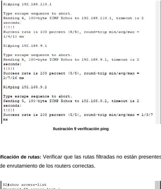
2.2 verificación de comunicación: Verificar comunicación entre routers mediante el
16
Ilustración 9 verificación ping
2.3 verificación de rutas: Verificar que las rutas filtradas no están presentes en las
tablas de enrutamiento de los routers correctas.
Ilustración 10 Access list
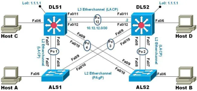
17 ESCENARIO 2
Una empresa de comunicaciones presenta una estructura Core acorde a la topología de red, en donde el estudiante será el administrador de la red, el cual deberá configurar e interconectar entre sí cada uno de los dispositivos que forman parte del escenario, acorde con los lineamientos establecidos para el direccionamiento IP, etherchannels, VLANs y demás aspectos que forman parte del escenario propuesto.
Ilustración 11 topología de red ccnp switch
Parte 1: Configurar la red de acuerdo con las especificaciones.
18 DLS1(config)#interface ran f0/1-24, g0/1-2 DLS1(config-if-range)#shutdown
DLS1(config-if-range)#exit
DLS1(config)#interface ran f0/11-12 DLS1(config-if-range)#no switchport
DLS1(config-if-range)#channel-group 12 mode active DLS1(config-if-range)#no shutdown
DLS1(config-if-range)#
1.2 asignación de nombres: Asignar un nombre a cada switch acorde al escenario
establecido.
Switch>ENABLE Switch#config
Configuring from terminal, memory, or network [terminal]? Enter configuration commands, one per line. End with CNTL/Z. Switch(config)#hostname DLS1
Switch>ENABLE Switch#config
Configuring from terminal, memory, or network [terminal]? Enter configuration commands, one per line. End with CNTL/Z. Switch(config)#hostname DLS2
19 Switch#config
Configuring from terminal, memory, or network [terminal]? Enter configuration commands, one per line. End with CNTL/Z. Switch(config)#hostname ALS1
Switch>ENABLE Switch#config
Configuring from terminal, memory, or network [terminal]? Enter configuration commands, one per line. End with CNTL/Z. Switch(config)#hostname ALS2
1.3 configuración de puertos troncales: Configurar los puertos troncales y
Port-channels tal como se muestra en el diagrama.
1) La conexión entre DLS1 y DLS2 será un EtherChannel capa-3 utilizando LACP. Para DLS1 se utilizará la dirección IP 10.12.12.1/30 y para DLS2 utilizará 10.12.12.2/30.
2) Los Port-channels en las interfaces Fa0/7 y Fa0/8 utilizarán LACP. 3) Los Port-channels en las interfaces F0/9 y fa0/10 utilizará PAgP.
4) Todos los puertos troncales serán asignados a la VLAN 800 como la VLAN nativa.
DLS1
DLS1(config)#interface ran f0/11-12
DLS1(config-if-range)#channel-group 12 mode active DLS1(config-if-range)#exit
DLS1(config)#interface port-channel 12
20 DLS1(config-if)#exit
DLS1(config)#int ran f0/7-10
DLS1(config-if-range)#switchport trunk encapsulation dot1q DLS1(config-if-range)#switchport trunk native vlan 800 DLS1(config-if-range)#switchport mode trunk
DLS1(config-if-range)#switchport nonegotiate DLS1(config-if-range)#no shutdown
DLS1(config-if-range)#exit
DLS1(config)#int ran f0/7-8
DLS1(config-if-range)#desc member of po1 to ALS1 DLS1(config-if-range)#channel-group 1 mode active DLS1(config-if-range)#exit
DLS1(config)#
DLS1(config)#int ran f0/9-10
DLS1(config-if-range)#desc member of po4 to ALS2 DLS1(config-if-range)#channel-group 4 mode desirable DLS1(config-if-range)#
Creating a port-channel interface Port-channel 4
DLS1(config-if-range)#exit DLS1(config)#
DLS1#
DLS2
21 DLS2(config-if-range)#no switchport DLS2(config-if-range)#
DLS2(config-if-range)#channel-group 12 mode active DLS2(config-if-range)#
Creating a port-channel interface Port-channel 12 DLS2(config-if-range)#no shutdown
DLS2(config-if-range)#exit
DLS2(config)#interface port-channel 12
DLS2(config-if)#ip address 10.12.12.2 255.255.255.252 DLS2(config-if)#exit
DLS2(config)#int ran f0/7-10
DLS2(config-if-range)#switchport trunk encapsulation dot1q DLS2(config-if-range)#switchport trunk native vlan 800 DLS2(config-if-range)#switchport mode trunk
DLS2(config-if-range)#
DLS2(config-if-range)#switchport nonegiate DLS2(config-if-range)#no shutdown
DLS2(config-if-range)#exit DLS2(config)#
DLS2(config)#
DLS2(config)#int ran f0/7-8
DLS2(config-if-range)#desc member of po1 to ALS2 DLS2(config-if-range)#channel-group 2 mode active
DLS2(config-if-range)#
Creating a port-channel interface Port-channel 2
22 DLS2(config)#int ran f0/9-10
DLS2(config-if-range)#desc member of po3 to ALS1 DLS2(config-if-range)#channel-group 3 mode desirable DLS2(config-if-range)#
DLS2(config-if-range)#exit DLS2(config)#
ALS1
ALS1>enable ALS1#config
Configuring from terminal, memory, or network [terminal]? Enter configuration commands, one per line. End with CNTL/Z. ALS1(config)#int ran f0/7-10
ALS1(config-if-range)#switchport trunk native vlan 800 ALS1(config-if-range)#switchport mode trunk
ALS1(config-if-range)#
ALS1(config-if-range)#switchport nonegotiate ALS1(config-if-range)#no shutdown
ALS1(config-if-range)#exit ALS1(config)#int ran f0/7-8
ALS1(config-if-range)#desc member of po1 to DLS1 ALS1(config-if-range)#channel-group 1 mode active ALS1(config-if-range)#
Creating a port-channel interface Port-channel 1
ALS1(config-if-range)#switchport trunk allowed vlan
23 ALS1(config-if-range)#exit
ALS1(config)#int ran f0/9-10
ALS1(config-if-range)#desc member of po 3 to DLS2 ALS1(config-if-range)#channel-group 3 mode desirable ALS1(config-if-range)#
Creating a port-channel interface Port-channel 3
ALS1(config-if-range)#switchport trunk allowed vlan
12,123,234,800,1010,1111,3456 ALS1(config-if-range)#no shutdown ALS1(config-if-range)#exit
ALS1(config)#int vlan 3456
ALS1(config-if)#ip address 10.34.56.101 255.255.255.0 ALS1(config-if)#no shutdown
ALS1(config-if)#exit
ALS1(config)#ip default-gateway 10.34.56.254 ALS1(config)#
ALS2 ALS2>ENABLE
ALS2#config
Configuring from terminal, memory, or network [terminal]? Enter configuration commands, one per line. End with CNTL/Z. ALS2(config)#int ran f0/7-10
ALS2(config-if-range)#switchport trunk native vlan 800 ALS2(config-if-range)#switchport mode trunk
ALS2(config-if-range)#
ALS2(config-if-range)#switchport nonegotiate ALS2(config-if-range)#exit
24 ALS2(config-if-range)#
ALS2(config-if-range)#desc member of po2 to DLS2 ALS2(config-if-range)#channel-group 2 mode active ALS2(config-if-range)#
Creating a port-channel interface Port-channel 2
ALS2(config-if-range)#switchport trunk allowed vlan
12,123,234,800,1010,1111,3456 ALS2(config-if-range)#no shutdown ALS2(config-if-range)#exit
ALS2(config)#int ran f0/9-10
ALS2(config-if-range)#desc member of po 4 to DLS1 ALS2(config-if-range)#channel-group 4 mode desirable ALS2(config-if-range)#
Creating a port-channel interface Port-channel 4
ALS2(config-if-range)#switchport trunk allowed vlan
12,123,234,800,1010,1111,3456 ALS2(config-if-range)#
ALS2(config-if-range)#no shutdown ALS2(config-if-range)#exit
ALS2(config)#int vlan 3456
ALS2(config-if)#ip add 10.34.56.102 255.255.255.0 ALS2(config-if)#no shutdown
ALS2(config-if)#exit ALS2(config)#
ALS2(config)#ip default-gateway 10.34.56.254 ALS2(config)#
1.4 Configuración de switchs Configurar DLS1, ALS1, y ALS2 para utilizar VTP
25
1) Utilizar el nombre de dominio UNAD con la contraseña cisco123 2) Configurar DLS1 como servidor principal para las VLAN.
3) Configurar ALS1 y ALS2 como clientes VTP.
DLS1 DLS1(config)#vtp mode server Device mode already VTP SERVER. DLS1(config)#vtp domain UNAD
Changing VTP domain name from NULL to UNAD DLS1(config)#vtp domain UNAD
Domain name already set to UNAD. DLS1(config)#vtp password cisco123
Setting device VLAN database password to cisco123 DLS1(config)#vtp password cisco123
Password already set to cisco123 DLS1(config)#
ALS1 ALS1>enable
ALS1#config
Configuring from terminal, memory, or network [terminal]? Enter configuration commands, one per line. End with CNTL/Z. ALS1(config)#vtp mode client
Setting device to VTP CLIENT mode. ALS1(config)#vtp domain UNAD
26 ALS1(config)#vtp domain UNAD
Domain name already set to UNAD. ALS1(config)#vtp password cisco123
Setting device VLAN database password to cisco123 ALS1(config)#vtp password cisco123
Password already set to cisco123 ALS1(config)#exit
ALS2 ALS2>enable
ALS2#config
Configuring from terminal, memory, or network [terminal]? Enter configuration commands, one per line. End with CNTL/Z. ALS2(config)#vtp mode client
Setting device to VTP CLIENT mode. ALS2(config)#vtp mode client
Device mode already VTP CLIENT. ALS2(config)#vtp domain UNAD
Changing VTP domain name from NULL to UNAD ALS2(config)#vtp domain UNAD
Domain name already set to UNAD. ALS2(config)#vtp password cisco123
Setting device VLAN database password to cisco123 ALS2(config)#vtp password cisco123
27 ALS2(config)#exit
ALS2#
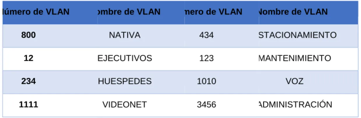
1.5 asignación de Vlan: Configurar en el servidor principal las siguientes VLAN:
Número de VLAN Nombre de VLAN Número de VLAN Nombre de VLAN
800 NATIVA 434 ESTACIONAMIENTO
12 EJECUTIVOS 123 MANTENIMIENTO
234 HUESPEDES 1010 VOZ
1111 VIDEONET 3456 ADMINISTRACIÓN
Tabla 1 Asignacion de vlans
DLS1
DLS1(config)#
DLS1(config)#vtp mode transparent
Setting device to VTP TRANSPARENT mode. DLS1(config)#vlan 800
DLS1(config-vlan)#name NATIVE DLS1(config-vlan)#vlan 12
DLS1(config-vlan)#name EJECUTIVOS DLS1(config-vlan)#vlan 234
DLS1(config-vlan)#name HUESPEDES DLS1(config-vlan)#vlan 1111
DLS1(config-vlan)#name VIDEONET DLS1(config-vlan)#vlan 434
DLS1(config-vlan)#name ESTACIONAMIENTO DLS1(config-vlan)#vlan 123
28 DLS1(config-vlan)#name VOZ DLS1(config-vlan)#vlan 3456 DLS1(config-vlan)#name ADMINISTRACION DLS1(config-vlan)#exit DLS1(config)#
1.6 suspensión de Vlan 434: En DLS1, suspender la VLAN 434.
1.7 configuración VTP: Configurar DLS2 en modo VTP transparente VTP utilizando
VTP versión 2, y configurar en DLS2 las mismas VLAN que en DLS1.
DLS2(config)#vtp mode transparent
Setting device to VTP TRANSPARENT mode. DLS2(config)#
29 DLS2(config-vlan)#exit
DLS2(config)#vlan 1010 DLS2(config-vlan)#name VOZ DLS2(config-vlan)#exit
DLS2(config)#vlan 3456
DLS2(config-vlan)#name ADMINISTRACION DLS2(config-vlan)#exit
DLS2(config)#
1.8 Suspensión Vlan 434: Suspender VLAN 434 en DLS2.
1.9 creación Vlan 567: En DLS2, crear VLAN 567 con el nombre de CONTABILIDAD.
La VLAN de CONTABILIDAD no podrá estar disponible en cualquier otro Switch de la red.
DLS2(config)#vlan 567
DLS2(config-vlan)#name CONTABILIDAD DLS2(config-vlan)#exit
DLS2(config)# DLS2#
%SYS-5-CONFIG_I: Configured from console by console
1.10 configuración spanning tree: Configurar DLS1 como Spanning tree root para
las VLAN 1, 12, 434, 800, 1010, 1111 y 3456 y como raíz secundaria para las VLAN 123 y 234.
DLS1(config)#spanning-tree vlan 1,12,434,800,1010,1111,3456 root primary DLS1(config)#spanning-tree vlan 123,234 root secondary
DLS1(config)# DLS1#
30
1.11 Configuración DLS2 como spanning tree: Configurar DLS2 como Spanning tree
root para las VLAN 123 y 234 y como una raíz secundaria para las VLAN 12, 434, 800, 1010, 1111 y 3456.
DLS2(config)#spanning-tree vlan 123,234 root primary
DLS2(config)#spanning-tree vlan 12,434,800,1010,3456 root secondary DLS2(config)#
1.12 configuración puertos troncales: Configurar todos los puertos como troncales
de tal forma que solamente las VLAN que se han creado se les permitirá circular a través de éstos puertos.
DLS1 DLS1(config)#interface port-channel 1
DLS1(config-if)#switchport trunk allowed vlan 12,123,234,800,1010,1111,3456 DLS1(config-if)#exit
DLS1(config)#interface port-channel 4
DLS1(config-if)#switchport trunk allowed vlan 12,123,234,800,1010,1111,3456 DLS1(config-if)#
DLS1#
%SYS-5-CONFIG_I: Configured from console by console
DLS2
DLS2(config)#interface port-channel 2
31 DLS2(config-if)#exit
DLS2(config)#interface port-channel 3
DLS2(config-if)#switchport trunk allowed vlan 12,123,234,800,1010,1111,3456 DLS2(config-if)#exit
1.13 configuración interfaces: Configurar las siguientes interfaces como puertos de
acceso, asignados a las VLAN de la siguiente manera:
Interfaz DLS1 DLS2 ALS1 ALS2
Interfaz Fa0/6 3456 12 , 1010 123, 1010 234
Interfaz Fa0/15 1111 1111 1111 1111
Interfaces F0 /16-18 567
Tabla 2 configuracion de interfaces
DLS1
DLS1(config)#interface f0/6 DLS1(config-if)#switchport
DLS1(config-if)#switchport access vlan 3456 DLS1(config-if)#no shutd
DLS1(config-if)# DLS1(config-if)#exit DLS1(config)#int f0/15 DLS1(config-if)#switchport
DLS1(config-if)#switchport access vlan 1111 DLS1(config-if)#no shutdown
32 DLS1(config-if)#exit DLS1(config)# DLS2 DLS2(config)#interface f0/6 DLS2(config-if)# DLS2(config-if)#swi DLS2(config-if)#switchport
DLS2(config-if)#switchport access vlan 12 DLS2(config-if)#switchport voice vlan 1010 DLS2(config-if)#no shutdown DLS2(config-if)#exit DLS2(config)#int f0/15 DLS2(config-if)#sw DLS2(config-if)#switchport DLS2(config-if)#switchport acces
DLS2(config-if)#switchport access vlan 1111 DLS2(config-if)#no shut
DLS2(config-if)#exit
DLS2(config)#int ran f0/16-18 DLS2(config-if-range)#sw
DLS2(config-if-range)#switchport DLS2(config-if-range)#switchport acces
33 ALS1#config
Configuring from terminal, memory, or network [terminal]? Enter configuration commands, one per line. End with CNTL/Z. ALS1(config)#int f0/6
ALS1(config-if)#switchport access vlan 123 ALS1(config-if)#switchport voice vlan 1010 ALS1(config-if)#no shutdown
ALS1(config-if)#exit ALS1(config)#int f0/15
ALS1(config-if)#switchport access vlan 1111 ALS1(config-if)#no shutdown ALS1(config-if)#exit ALS1(config)# ALS2 ALS2>enable ALS2#config
Configuring from terminal, memory, or network [terminal]? Enter configuration commands, one per line. End with CNTL/Z. ALS2(config)#int f0/6
ALS2(config-if)#switchport access vlan 234 ALS2(config-if)#no shutdown
ALS2(config-if)#exit ALS2(config)#int f0/15
ALS2(config-if)#switchport access vlan 1111 ALS2(config-if)#no shutdown
ALS2(config-if)#exit ALS2(config)#
34
2.1 verificación de vlans: Verificar la existencia de las VLAN correctas en todos los
switches y la asignación de puertos troncales y de acceso
2.2 Verificación etherchannel: Verificar que el EtherChannel entre DLS1 y ALS1 está
configurado correctamente.
2.3 verificación spanning tree: Verificar la configuración de Spanning tree entre
DLS1 o DLS2 para cada VLAN.
35
Ilustración 13 show vlan brief dls1
36
Ilustración 15 show vlan brief als1
37
Ilustración 17 verificación etherchannel y protocolos dls1
38
CONCLUSIONES
En el presente trabajo se identificaron conceptos básicos y de conocimiento general del curso diplomado de profundización cisco ccnp siendo capaz de formular problemas en contextos dados dentro del marco de la practica como ingenieros de telecomunicaciones, adicional se permitió el conocimiento y estudio de las actividades a desarrollar a lo largo del curso, caracterizándolas por descripción y peso evaluativo interactuando con diferentes herramientas como lo son packet tracer y GNS3.
Teniendo en cuenta la complejidad de los escenarios propuestos es claro recomendar tener unos conocimientos previos básicos de la configuración de dispositivos de red y sus respectivos software lo que permitirá un mayor entendimiento y conocimiento a implementar.
39
BIBLIOGRAFIA
Froom, R., Frahim, E. (2015). CISCO Press (Ed). Spanning Tree Implementation. Implementing Cisco IP Switched Networks (SWITCH) Foundation Learning Guide CCNP SWITCH 300-115. Recuperado de https://1drv.ms/b/s!AmIJYei- NT1IlnWR0hoMxgBNv1CJ
Froom, R., Frahim, E. (2015). CISCO Press (Ed). InterVLAN Routing. Implementing Cisco IP Switched Networks (SWITCH) Foundation Learning Guide CCNP SWITCH 300-115. Recuperado de https://1drv.ms/b/s!AmIJYei-NT1IlnWR0hoMxgBNv1CJ Froom, R., Frahim, E. (2015). CISCO Press (Ed). Fundamentals Review. Implementing Cisco IP Switched Networks (SWITCH) Foundation Learning Guide CCNP SWITCH 300-115. Recuperado de https://1drv.ms/b/s!AmIJYei- NT1IlnWR0hoMxgBNv1CJ
Teare, D., Vachon B., Graziani, R. (2015). CISCO Press (Ed). Basic Network and Routing Concepts. Implementing Cisco IP Routing (ROUTE) Foundation Learning Guide CCNP ROUTE 300-101. Recuperado de https://1drv.ms/b/s!AmIJYei- NT1IlnMfy2rhPZHwEoWx
Teare, D., Vachon B., Graziani, R. (2015). CISCO Press (Ed). EIGRP Implementation. Implementing Cisco IP Routing (ROUTE) Foundation Learning Guide CCNP ROUTE 300-101. Recuperado de https://1drv.ms/b/s!AmIJYei- NT1IlnMfy2rhPZHwEoWx
40