EVALUACION FINAL
PRUEBAS DE HABILIDADES PRÁCTICAS CISCO CCNP
EMERSON RODRIGO MESA RODRIGUEZ
UNIVERSIDAD NACIONAL ABIERTA Y A DISTANCIA INGENIERIA EN TELECOMUNICACIONES
DIPLOMADO CISCO CCNP CÚCUTA
EVALUACION PRUEBA DE HABILIDADES PRÁCTICAS CISCO CCNP
EMERSON RODRIGO MESA RODRIGUEZ
Diplomado de profundización cisco CCNP prueba de habilidades prácticas
Gerardo Granados Acuña Magíster en Telemática
UNIVERSIDAD NACIONAL ABIERTA Y A DISTANCIA INGENIERIA EN TELECOMUNICACIONES
DIPLOMADO CISCO CCNP CÚCUTA
3
NOTA DE ACEPTACIÓN
__________________________________ __________________________________ __________________________________
__________________________________ __________________________________ __________________________________
__________________________________ Presidente del jurado
__________________________________ Jurado
__________________________________
Jurado
4
TABLA DE CONTENIDO
LISTA DE TABLAS ... 5
LISTA DE FIGURAS ... 6
GLOSARIO ... 7
RESUMEN ... 8
INTRODUCCIÓN ... 9
DESARROLLO ... 10
ESCENARIO ... 10
CONCLUSIONES ... 40
5
LISTA DE TABLAS
Tabla 1. Direccionamiento Routers……….. 10
6
LISTA DE FIGURAS
Figura 1. Escenario 1 ……… 10
Figura 2. Conectividad R1……… 18
Figura 3.Conectividad R2……… 19
Figura 4. Conectividad R3……… 19
Figura 5. Rutas R1 ……….. 20
Figura 6. Rutas R2……….. 20
Figura 7. Rutas R3……….. 21
Figura 8. Topologia de red………. 22
Figura 9. VLANs DLS1..………. 38
Figura 10. VLANs DLS2………. 38
Figura 11. VLANs ALS1………. 38
Figura 12. VLANs ALS2 ……… 39
Figura 13. Spanning tree DLS1……… 39
7 GLOSARIO
RED: Conjunto de dispositivos conectados entre sí por medio de medios de transmisión fisicos o inalambricos para la transmisión de información
Router: Dispositivo capaz de interconectar equipos atraves del enrutamiento de paquetes de datos en diferentes niveles.
Switch: Se encuentra por debajo del router y su funcion es interconectar los host de la red a traves de la capa de enlace de datos.
VLAN: Virtual LAN (Red de área local y virtual) permite crear redes que lógicamente son independientes, aunque estas se encuentren dentro de una misma red física.
IP: Internet Protocol, además es la identiicación de un dispositivo en la red
OSPF: OSPF (Open Shortest Path First) Tiene una respuesta rapida y sin bucles. EIGRP: Enhanced Interior Gateway Routing Protocol (EIGRP), es un protocolo vector distancia, osea que busca la ruta con el menor número de saltos. Host: Dispositivo que hace parte de la red (tablets, portatiles, etc.)
LACP: Link Aggregation Control Protocol, protocolo que se encarga de unir varias conexiones de red en una sola conexión virtual para dar una mayor velocidad de acceso.
8 RESUMEN
Este trabajo evidencia la asimilación y puesta en práctica de los conceptos de situaciones y problemas en torno al Networking mediante el montaje de dos escenarios distintos donde en uno de ellos se realiza el montaje, configuración e interconexion de los dispositivos, todo acorde los lineamientos para el
direccionamiento IP que se entregaron se realizan las configuracione en las interfaces con las direcciones IPv4 e IPv6 para la implementación de las familias OSPFv3 y se establecen las conexiones seriales entre los routers y se configura el protocolo EIGRP. En el segundo escenario presentamos una estructura core en la que instalamos unos switch donde utilizaremos protocolos VTP para la
propagación de unas VLAN establecidas para los diferentes areas del cliente en las que se busca sacar mayor provecho a la red, esto mediante la configuración de distintos protocolos diseñados para una mayor efectividad en cuanto al
funcionamiento de los dispositivos y la seguridad de los datos.
Palabras Clave: CCNP, EIGRP, OSPF, GNS3.
ABSTRACT
This work evidences the assimilation and implementation of the concepts of situations and problems around Networking by assembling two different scenarios where in one of them the assembly, configuration and interconnection of the
devices is carried out, all according to the guidelines for the IP addresses that were delivered are configured on the interfaces with the IPv4 and IPv6 addresses for the implementation of the OSPFv3 families and the serial connections between the routers are established and the EIGRP protocol is configured. In the second
scenario we present a core structure in which we install a switch where we will use VTP protocols for the propagation of established VLANs for the different areas of the client in which it is sought to make the most of the network, this through the configuration of different protocols designed for greater effectiveness in terms of device operation and data security.
9
INTRODUCCIÓN
En este documento se encuentra el desarrollo de los escenarios planteados como prueba de las habilidades prácticas adquiridas en el desarrollo del diplomado de profundización Cisco CCNP, a continuación se encuentran dos escenarios
distintos donde mediante herramientas de simulación como Packet Tracer o GNS3 se plantean distintas problemáticas y situaciones comunes que se pueden
10
DESARROLLO
ESCENARIO 1
Una empresa de confecciones posee tres sucursales distribuidas en las ciudades de Bogotá, Medellín y Bucaramanga, en donde el estudiante será el administrador de la red, el cual deberá configurar e interconectar entre sí cada uno de los dispositivos que forman parte del escenario, acorde con los lineamientos establecidos para el direccionamiento IP, protocolos de enrutamiento y demás aspectos que forman parte de la topología de red.
Figura 1. Topología de red
Dispositivo Interfaz Dirección IP
R1 Bogotá G0/0 192.168.110.1 /24 G0/0 2001:DB8:ACAD:110 /64 S0/0/0 192.168.9.0 /30 S0/0/0 2001:DB8:ACAD:90 /64 R2 Bucaramanga G0/0 192.168.2.1 /24
G0/0 2001:DB8:ACAD:B /64 S0/0/1 192.168.9.4 /30 S0/0/1 2001:DB8:ACAD:91 /64
R3 Medellín G0/0 192.168.3.1
11
Parte 1: Configuración del escenario propuesto
1. Configurar las interfaces con las direcciones IPv4 e IPv6 que se muestran en la topología de red.
R1 Bogotá
R1#conf t
R1(config)#ipv6 unica
R1(config)#ipv6 unicast-routing R1(config)#int g0/0
R1(config-if)#ip address 192.168.110.1 255.255.255.0 R1(config-if)#ipv6 add 2001:DB8:ACAD:110::1/64
R1(config-if)#no shutdown R1(config)#int s3/0
R1(config-if)#ip address 192.168.9.1 255.255.255.252
R1(config-if)#ipv6 add 2001:DB8:ACAD:90::1/64
R2 Bucaramanga
R2#conf t
Enter configuration commands, one per line. End with CNTL/Z. R2(config)#ipv6 unicast-routing
R2(config)#int g0/0
R2(config-if)#ip address 192.168.2.1 255.255.255.0
R2(config-if)#ipv6 add
R2(config-if)#ipv6 address 2001:DB8:ACAD:B::1/64 R2(config-if)#no sh
12
R2(config-if)#ip address 192.168.9.2 255.255.255.252 R2(config-if)#ipv6 address 2001:DB8:ACAD:90::2/64 R3 Medellin
R3#conf t
Enter configuration commands, one per line. End with CNTL/Z. R3(config)#int g0/0
R3(config-if)#ip address 192.168.3.1 255.255.255.0 R3(config-if)#ipv6 address 2001:DB8:ACAD:C::1/64 R3(config-if)#no sh
R3(config-if)#
R3(config-if)#int s3/1
R3(config-if)#ip address 192.168.9.6 255.255.255.252
R3(config-if)#ipv6 address 2001:DB8:ACAD:91::2/64
2. Ajustar el ancho de banda a 128 kbps sobre cada uno de los enlaces seriales ubicados en R1, R2, y R3 y ajustar la velocidad de reloj de las conexiones de DCE según sea apropiado.
R1 Bogotá
R1(config-if)#clockrate 128000 R1(config-if)#bandw
R1(config-if)#bandwidth 128 R1(config-if)#
R2 Bucaramanga
R2(config-if)#BANDwidth 128 R2(config-if)#clockrate 128000
R3 Medellin
13 R3(config-if)#no sh
R3(config-if)#
3. En R2 y R3 configurar las familias de direcciones OSPFv3 para IPv4 e IPv6. Utilice el identificador de enrutamiento 2.2.2.2 en R2 y 3.3.3.3 en R3 para ambas familias de direcciones.
R2(config)#int s3/1
R2(config)#router ospfv3 1
R2(config-router)#address-fami
R2(config-router)#address-family ipv4 unicast R2(config-router-af)#router-id 2.2.2.2
R2(config-router-af)#exit-address-family R2(config-router)#address-fam
R2(config-router)#address-family ipv6 uni
R2(config-router)#address-family ipv6 unicast R2(config-router-af)#router-id 2.2.2.2
R2(config-router-af)#exit-address-family
R2(config-router)#
R3(config)#router ospfv3 1
R3(config-router)#address-family ipv4 unicast R3(config-router-af)#router-id 3.3.3.3
R3(config-router-af)#ex
R3(config-router-af)#passive-interface g0/0 R3(config-router-af)#exit-address-family R3(config-router)#address-family ipv6 uni
R3(config-router)#address-family ipv6 unicast R3(config-router-af)#rou
14 R3(config-router-af)# exit-address-family R3(config-router)#
4. En R2, configurar la interfaz F0/0 en el área 1 de OSPF y la conexión serial entre R2 y R3 en OSPF área 0.
R2#conf t
Enter configuration commands, one per line. End with CNTL/Z. R2(config)#int g0/0
R2(config-if)#ospfv3 1 ipv4 area 1 R2(config-if)#ospfv3 1 ipv6 area 1 R2(config-if)#int s3/1
R2(config-if)#ospfv3 1 ipv4 area 0 R2(config-if)#ospfv3 1 ipv6 area 0 R2(config-if)#
R3(config-if)#int s3/1
R3(config-if)#ospfv3 1 ipv4 area 0 R3(config-if)#ospfv3 1 ipv6 area 0
5. En R3, configurar la interfaz F0/0 y la conexión serial entre R2 y R3 en OSPF área 0.
R3(config)#int g0/0 R3(config-if)#
R3(config-if)#ospfv3 1 ipv6 area 0 R3(config-if)#ospfv3 1 ipv4 area 0 R3(config-if)#int s3/1
R3(config-if)#ospfv3 1 ipv4 area 0 R3(config-if)#ospfv3 1 ipv6 area 0
R2(config-if)#int s3/1
15
6. Configurar el área 1 como un área totalmente Stubby.
R2#conf t
Enter configuration commands, one per line. End with CNTL/Z. R2(config)#router ospfv3 1
R2(config-router)#add
R2(config-router)#address-family ipv4 unicast R2(config-router-af)#area 1 stub no-summary R2(config-router-af)#exi
R2(config-router-af)#exit-address-family R2(config-router)#address-family ipv6 unicast R2(config-router-af)#area 1 stub no-summary
7. Propagar rutas por defecto de IPv4 y IPv6 en R3 al interior del dominio OSPFv3. Nota: Es importante tener en cuenta que una ruta por defecto es diferente a la definición de rutas estáticas.
R3#conf t
R3(config)#router ospfv3 1
R3(config-router)#address-family ipv4 unicast
R3(config-router-af)#default-information originate always R3(config-router-af)#exit-address-family
R3(config-router)#address-family ipv6 unicast
R3(config-router-af)#default-information originate always R3(config-router-af)#exit-address-family
R3(config-router)#
8. Realizar la configuración del protocolo EIGRP para IPv4 como IPv6. Configurar la interfaz F0/0 de R1 y la conexión entre R1 y R2 para EIGRP con el sistema autónomo 101. Asegúrese de que el resumen automático está desactivado.
R1#conf t
R1(config)#router eigrp dual-stack R1(config-router)#add
R1(config-router)#address-family ipv4 unicast autonomous-system 4 R1(config-router-af)#af-int
16 R1(config-router-af-interface)#passive-interface R1(config-router-af-interface)#ex R1(config-router-af-interface)#exit-af-interface R1(config-router-af)#topo R1(config-router-af)#topology base R1(config-router-af-topology)#ex R1(config-router-af-topology)#exit-af-topology R1(config-router-af)#network 192.168.9.0 0.0.0.3 R1(config-router-af)#network 192.168.110.0 0.0.0.3 R1(config-router-af)#eigrp rou
R1(config-router-af)#eigrp router-id 1.1.1.1 R1(config-router-af)#ex
R1(config-router-af)#exit-address-family
R1(config-router)#address-family ipv6 unicast autonomous-system 6 R1(config-router-af)#af-in R1(config-router-af)#af-interface g0/0 R1(config-router-af)#topology base R1(config-router-af-topology)#ex R1(config-router-af-topology)#exit-af-topology R1(config-router-af)#eigrp rou
R1(config-router-af)#eigrp router-id 1.1.1.1 R1(config-router-af)#ex
R1(config-router-af)#exit-address-family R1(config-router)#
R2#conf t
R2(config)#router eigrp dual-stack R2(config-router)#add
R2(config-router)#address-family ipv4 unicast autonomous-system 4 R2(config-router-af)#network 192.168.9.0 0.0.0.3
R2(config-router-af)#eigrp rout
R2(config-router-af)#eigrp router-id 2.2.2.2 R2(config-router-af)#exit-address-family
17
R2(config-router-af)#eigrp router-id 2.2.2.2 R2(config-router-af)#ex
R2(config-router-af)#exit-address-family R2(config-router)#
9. Configurar las interfaces pasivas para EIGRP según sea apropiado.
R1(config-router)#address-family ipv6 unicast autonomous-system 6 R1(config-router-af)#af-interface g0/0
R1(config-router-af-interface)#passive-interface R1(config-router-af-interface)#exit-af-interface
10. En R2, configurar la redistribución mutua entre OSPF y EIGRP para IPv4 e IPv6. Asignar métricas apropiadas cuando sea necesario.
R2#conf t
Enter configuration commands, one per line. End with CNTL/Z. R2(config)#router eigrp dual-stack
R2(config-router)#address-family ipv4 unicast autonomous-system 4 R2(config-router-af)#topology base
R2(config-router-af-topology)#dist
R2(config-router-af-topology)#distribute-list R3-to-R1 out R2(config-router-af-topology)#red
R2(config-router-af-topology)#$e ospfv3 1 metric 10000 100 255 1 1500 R2(config-router-af-topology)#exit-af-topology
R2(config-router)#address-family ipv6 unicast autonomous-system 6 R2(config-router-af)#topology base
R2(config-router-af-topology)#red
R2(config-router-af-topology)#redistribute ospf 1 metric 10000 100 255 1 1500
R2(config-router-af-topology)#ex
R2(config-router-af-topology)#exit-af-topology R2(config-router-af)#exi
R2(config-router)#exi
11. En R2, de hacer publicidad de la ruta 192.168.3.0/24 a R1 mediante una lista de distribución y ACL.
R2(config)#ip acc
18
R2(config-std-nacl)#remark ACL to filter 192.168.3.0/24
R2(config-std-nacl)#deny 192.168.3.0 0.0.0.255 R2(config-std-nacl)#permit any
R2(config-std-nacl)#
Parte 2: Verificar conectividad de red y control de la trayectoria.
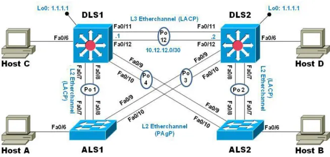
a. Registrar las tablas de enrutamiento en cada uno de los routers, acorde con los parámetros de configuración establecidos en el escenario propuesto.
R1#show ip route R2#show ip route R3#show ip route
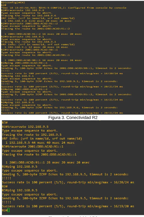
b. Verificar comunicación entre routers mediante el comando ping y traceroute.
19
Figura 3. Conectividad R2
20
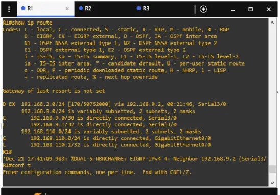
c. Verificar que las rutas filtradas no están presentes en las tablas de enrutamiento de los routers correctas.
Figura 5. Rutas R1
21
Figura 7. Rutas R3
Nota: Puede ser que Una o más direcciones no serán accesibles desde todos los routers después de la configuración final debido a la utilización de listas de
distribución para filtrar rutas y el uso de IPv4 e IPv6 en la misma red.
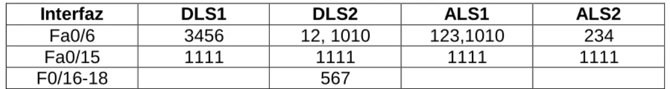
ESCENARIO 2
Una empresa de comunicaciones presenta una estructura Core acorde a la topología de red, en donde el estudiante será el administrador de la red, el cual deberá configurar e interconectar entre sí cada uno de los dispositivos que forman parte del escenario, acorde con los lineamientos establecidos para el
22
Figura 8. Topologia de red
Parte 1: Configurar la red de acuerdo con las especificaciones. a. Apagar todas las interfaces en cada switch.
Switch>en Switch#conf t Switch(config)#
Switch(config)#int g0/0 Switch(config)#shutdown Switch(config)#int g0/1
Switch(config)#shutdown Switch(config)#int g0/2 Switch(config)#shutdown
Switch(config)#int g0/3 Switch(config)#shutdown
Switch(config)#int g1/0 Switch(config)#shutdown
23 Switch(config)#shutdown
Switch(config)#int g1/2
Switch(config)#shutdown Switch(config)#int g1/3 Switch(config)#shutdown
Switch(config)#int g2/0 Switch(config)#shutdown
Switch(config)#int g2/1 Switch(config)#shutdown Switch(config)#int g2/2
Switch(config)#shutdown Switch(config)#int g2/3 Switch(config)#shutdown
b. Asignar un nombre a cada switch acorde al escenario establecido.
Switch>
Switch#conf t
Switch(config)# hostname DLS1 DLS1(config)#
Switch>
Switch#conf t
Switch(config)#hostname DLS2 DLS2(config)#
24 Switch(config)#hostname ALS1 ALS1(config)#
Switch> Switch#conf t
Switch(config)#hostname ALS2 ALS2(config)#
c. Configurar los puertos troncales y Port-channels tal como se muestra en el diagrama.
1) La conexión entre DLS1 y DLS2 será un EtherChannel capa-3 utilizando LACP. Para DLS1 se utilizará la dirección IP 10.12.12.1/30 y para DLS2 utilizará 10.12.12.2/30.
DLS1(config)# int g1/1
DLS1(config-if)# no switchport
DLS1(config-if)# channel-group 12 mode active
DLS1(config-if)#no shut DLS1(config-if)# int g1/2 DLS1(config-if)# no switchport
DLS1(config-if)# channel-group 12 mode active DLS1(config-if)#no shut
DLS1(config)# int port-channel 12
DLS1(config-if)# ip add 10.12.12.1 255.255.255.252
DLS2(config)# int g1/1
DLS2(config-if)# no switchport
DLS2(config-if)# channel-group 12 mode active
25 DLS2(config-if)# int g1/2
DLS2(config-if)# no switchport
DLS2(config-if)# channel-group 12 mode active DLS2(config-if)#no shut
DLS2(config)# int port-channel 12
DLS2(config-if)# ip add 10.12.12.2 255.255.255.252
2) Los Port-channels en las interfaces Fa0/7 y Fa0/8 utilizarán LACP.
DLS1(config)# int g0/1
DLS1(config-if)#channel-group 1 mode active
DLS1(config-if)#int g0/2
DLS1(config-if)#channel-group 1 mode active
DLS2(config)# int g0/1
DLS2(config-if)#channel-group 2 mode active DLS2(config-if)#int g0/2
DLS2(config-if)#channel-group 2 mode active
ALS1(config)# int g0/1
ALS1(config-if)#channel-group 1 mode active ALS1(config-if)#int g0/2
ALS1(config-if)#channel-group 1 mode active
ALS2(config)# int g0/1
ALS2(config-if)#channel-group 2 mode active ALS2(config-if)#int g0/2
26
3) Los Port-channels en las interfaces F0/9 y fa0/10 utilizará PAgP.
DLS1(config)# int g0/3
DLS1(config-if)#channel-group 4 mode desirable DLS1(config)# int g1/0
DLS1(config-if)#channel-group 4 mode desirable
DLS2(config)# int g0/3
DLS2(config-if)#channel-group 3 mode desirable DLS2(config)# int g1/0
DLS2(config-if)#channel-group 3 mode desirable
ALS1(config)# int g0/3
ALS1(config-if)#channel-group 3 mode desirable
ALS1(config)# int g1/0
ALS1(config-if)#channel-group 3 mode desirable
ALS2(config)# int g0/3
ALS2(config-if)#channel-group 4 mode desirable ALS2(config)# int g1/0
ALS2(config-if)#channel-group 4 mode desirable
4) Todos los puertos troncales serán asignados a la VLAN 800 como la VLAN nativa.
ALS1#conf t
ALS1(config)#int g0/1
ALS1(config-if)# switchport trunk encapsulation dot1q
27 ALS1(config-if)# switchport mode trunk ALS1(config-if)# switchport nonegotiate
ALS1(config-if)#int g0/2
ALS1(config-if)# switchport trunk encapsulation dot1q ALS1(config-if)# switchport trunk native vlan 800
ALS1(config-if)# switchport mode trunk ALS1(config-if)# switchport nonegotiate ALS1(config-if)#int g0/3
ALS1(config-if)# switchport trunk encapsulation dot1q ALS1(config-if)# switchport trunk native vlan 800 ALS1(config-if)# switchport mode trunk
ALS1(config-if)# switchport nonegotiate ALS1(config)#int g1/0
ALS1(config-if)# switchport trunk encapsulation dot1q
ALS1(config-if)# switchport trunk native vlan 800 ALS1(config-if)# switchport mode trunk
ALS1(config-if)# switchport nonegotiate
ALS2#conf t
ALS2(config)#int g0/1
ALS2(config-if)# switchport trunk encapsulation dot1q ALS2(config-if)# switchport trunk native vlan 800
ALS2(config-if)# switchport mode trunk ALS2(config-if)# switchport nonegotiate ALS2(config-if)#int g0/2
28 ALS2(config-if)# switchport nonegotiate ALS2(config-if)#int g0/3
ALS2(config-if)# switchport trunk encapsulation dot1q ALS2(config-if)# switchport trunk native vlan 800 ALS2(config-if)# switchport mode trunk
ALS2(config-if)# switchport nonegotiate ALS2(config)#int g1/0
ALS2(config-if)# switchport trunk encapsulation dot1q
ALS2(config-if)# switchport trunk native vlan 800 ALS2(config-if)# switchport mode trunk
ALS2(config-if)# switchport nonegotiate
DLS1#conf t
DLS1(config)#int g0/1
DLS1(config-if)# switchport trunk encapsulation dot1q DLS1(config-if)# switchport trunk native vlan 800
DLS1(config-if)# switchport mode trunk DLS1(config-if)# switchport nonegotiate DLS1(config-if)#int g0/2
DLS1(config-if)# switchport trunk encapsulation dot1q DLS1(config-if)# switchport trunk native vlan 800
DLS1(config-if)# switchport mode trunk DLS1(config-if)# switchport nonegotiate DLS1(config-if)#int g0/3
29 DLS1(config-if)# switchport nonegotiate DLS1(config)#int g1/0
DLS1(config-if)# switchport trunk encapsulation dot1q DLS1(config-if)# switchport trunk native vlan 800 DLS1(config-if)# switchport mode trunk
DLS1(config-if)# switchport nonegotiate DLS1(config-if)# no shut
DLS2#conf t
DLS2(config)#int g0/1
DLS2(config-if)# switchport trunk encapsulation dot1q
DLS2(config-if)# switchport trunk native vlan 800 DLS2(config-if)# switchport mode trunk
DLS2(config-if)# switchport nonegotiate
DLS2(config-if)#int g0/2
DLS2(config-if)# switchport trunk encapsulation dot1q DLS2(config-if)# switchport trunk native vlan 800
DLS2(config-if)# switchport mode trunk DLS2(config-if)# switchport nonegotiate DLS2(config-if)# no shut
DLS2(config-if)#int g0/3
DLS2(config-if)# switchport trunk encapsulation dot1q
DLS2(config-if)# switchport trunk native vlan 800 DLS2(config-if)# switchport mode trunk
DLS2(config-if)# switchport nonegotiate
DLS2(config)#int g1/0
30 DLS2(config-if)# switchport mode trunk DLS2(config-if)# switchport nonegotiate
ALS2(config-if)# no shut
d. Configurar DLS1, ALS1, y ALS2 para utilizar VTP versión 3
1) Utilizar el nombre de dominio UNAD con la contraseña cisco123
DLS1#conf t
DLS1(config)#vtp domain UNAD DLS1(config)#vtp version 3
DLS1(config)#vtp password cisco123
ALS1#CONF T
ALS1(config)#vtp domain UNAD ALS1(config)#vtp version 3
ALS1(config)#vtp password cisco123
ALS2#conf term
ALS2(config)#vtp domain UNAD
ALS2(config)#vtp version 3
ALS2(config)#vtp password cisco123
2) Configurar DLS1 como servidor principal para las VLAN.
DLS1(config)#exit DLS1#conf t
31
This system is becoming primary server for feature vlan No conflicting VTP3 devices found.
Do you want to continue? [confirm] DLS1#
3) Configurar ALS1 y ALS2 como clientes VTP.
ALS1(config)#mode client
ALS2(config)#mode client
e. Configurar en el servidor principal las siguientes VLAN:
Número de VLAN Nombre de VLAN Número de VLAN Nombre de VLAN
800 Nativa 434 Estacionamiento
12 Ejecutivos 123 Mantenimiento
234 Huespedes 1010 Voz
1111 Videonet 3456 Administración
Tabla 2. Direccionamiento VLAN DLS1#conf term
DLS1(config)#vlan 800
DLS1(config-vlan)#name NATIVA DLS1(config-vlan)#exit
DLS1(config)#vlan 434
DLS1(config-vlan)#name ESTACIONAMIENTO DLS1(config-vlan)#vlan 12
DLS1(config-vlan)#name EJECUTIOS DLS1(config-vlan)#vlan 123
DLS1(config-vlan)#name MANTENIMIENTO DLS1(config-vlan)#vlan 234
32 DLS1(config-vlan)#vlan 1010
DLS1(config-vlan)#name VOZ
DLS1(config-vlan)#vlan 1111
DLS1(config-vlan)#name VIDEONET DLS1(config-vlan)#vlan 3456
DLS1(config-vlan)#name ADMINISTRACIÓN DLS1(config-vlan)#EXIT
DLS1(config)#
f. En DLS1, suspender la VLAN 434.
DLS1#conf t
DLS1(config)#vlan 434
DLS1(config-vlan)#state suspend
DLS1(config)#vlan 800
g. Configurar DLS2 en modo VTP transparente VTP utilizando VTP versión 2, y configurar en DLS2 las mismas VLAN que en DLS1.
DLS2>en Password: DLS2#conf t
DLS2(config)#vtp version 2
DLS2(config)#vtp mode transparent DLS2(config)#vlan 800
DLS2(config-vlan)#name NATIVA DLS2(config)#vlan 434
33 DLS2(config-vlan)#vlan 12
DLS2(config-vlan)#name EJECUTIVOS
DLS2(config-vlan)#vlan 123
DLS2(config-vlan)#name MANTENIMIENTO DLS2(config-vlan)#vlan 234
DLS2(config-vlan)#name HUESPEDES DLS2(config-vlan)#vlan 1010
DLS2(config-vlan)#name VOZ
DLS2(config-vlan)#vlan 1111
DLS2(config-vlan)#name VIDEONET DLS2(config-vlan)#vlan 3456
DLS2(config-vlan)#name ADMINISTRACIÓN DLS2(config-vlan)#EXIT
DLS2(config)#
h. Suspender VLAN 434 en DLS2.
DLS2#conf t
DLS2(config)#vlan 434
DLS2(config-vlan)#state suspend
i. En DLS2, crear VLAN 567 con el nombre de CONTABILIDAD. La VLAN de CONTABILIDAD no podrá estar disponible en cualquier otro Switch de la red.
DLS2(config)#vlan 567
DLS2(config-vlan)#name CONTABILIDAD
34
j. Configurar DLS1 como Spanning tree root para las VLAN 1, 12, 434, 800, 1010, 1111 y 3456 y como raíz secundaria para las VLAN 123 y 234.
DLS1(config)#spanning-tree vlan 1, 12, 434, 800, 1010, 1111, 3456 root primary DLS1(config)#spanning-tree vlan 123, 234 root secondary
k. Configurar DLS2 como Spanning tree root para las VLAN 123 y 234 y como una raíz secundaria para las VLAN 12, 434, 800, 1010, 1111 y 3456.
DLS2(config)#spanning-tree vlan 123, 234 root primary
DLS2(config)#spanning-tree vlan 12, 434, 800, 1010, 1111, 3456 root secondary
l. Configurar todos los puertos como troncales de tal forma que solamente las VLAN que se han creado se les permitirá circular a través de éstos puertos.
DLS1>en Password:
DLS1#conf term
DLS1(config)#int range g0/1-3, g1/0
DLS1(config-if-range)#switchport trunk allowed vlan 12,123,234,800,1010,1111,3456
DLS1(config-if-range)#exit
DLS2(config)#int range g0/1-3, g1/0
DLS2(config-if-range)#switchport trunk allowed vlan 12,123,234,800,1010,1111,3456
DLS2(config-if-range)#exit
35 ALS1#conf term
ALS1(config)#int range g0/1-3, g1/0
ALS1(config-if-range)#switchport trunk allowed vlan 12,123,234,800,1010,1111,3456
ALS1(config-if-range)#exit
ALS2>en
Password: ALS2#conf term
ALS2(config)#int range g0/1-3, g1/0
ALS2(config-if-range)#switchport trunk allowed vlan 12,123,234,800,1010,1111,3456
ALS2(config-if-range)#exit
m. Configurar las siguientes interfaces como puertos de acceso, asignados a las VLAN de la siguiente manera:
Interfaz DLS1 DLS2 ALS1 ALS2
Fa0/6 3456 12, 1010 123,1010 234
Fa0/15 1111 1111 1111 1111
F0/16-18 567
Tabla 3. interfaces VLAN DLS1#conf term
DLS1(config)#int g1/3
DLS1(config-if)#switchport host
DLS1(config-if)#switchport mode access
DLS1(config-if)#switchport access vlan 3456 DLS1(config-if)#no shut
DLS1(config-if)#int g2/1
DLS1(config-if)#switchport host
DLS1(config-if)#switchport mode access
36 DLS1(config-if)#no shutdown
DLS2>en Password: DLS2#conf term
DLS2(config)#int g1/3
DLS2(config-if)#switchport host
DLS2(config-if)#switchport mode access
DLS2(config-if)#switchport access vlan 12 DLS2(config-if)#switchport voice 1010 DLS2(config-if)#no shutdown
DLS2(config-if)#int g2/1
DLS2(config-if)#switchport host
DLS2(config-if)#switchport mode access
DLS2(config-if)#switchport access vlan 1111 DLS2(config-if)#no shutdown
DLS2(config-if)#int range g2/2-3
DLS2(config-if-range)#switchport host
DLS2(config-if-range)#switchport mode access DLS2(config-if-range)#switchport access vlan 567
DLS2(config-if-range)#no shut
ALS1>en Password: ALS1#conf term
ALS1(config)#int g1/3
ALS1(config-if)#switchport host
37 ALS1(config-if)#switchport access vlan 123 ALS1(config-if)#switchport voice vlan 1010
ALS1(config-if)#no shut ALS1(config-if)#int g2/1
ALS1(config-if)#switchport host
ALS1(config-if)#switchport mode access ALS1(config-if)#switchport access vlan 1111 ALS1(config-if)#no shutdown
ALS2>en Password:
ALS2#conf term ALS2(config)#int g1/3
ALS2(config-if)#switchport host
ALS2(config-if)#switchport mode access ALS2(config-if)#switchport access vlan 234 ALS2(config-if)#no shutdown
ALS2(config-if)#int g2/1
ALS2(config-if)#switchport host
ALS2(config-if)#switchport mode access
ALS2(config-if)#switchport access vlan 1111 ALS2(config-if)#no shutdown
Part 2: conectividad de red de prueba y las opciones configuradas.
38
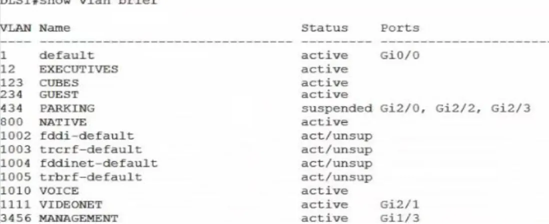
Figura 9. VLANs DLS1
Figura 10. VLANs DLS2
39
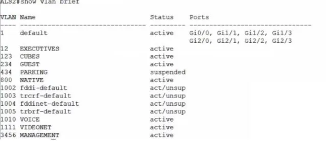
Figura 12. VLANs ALS2
b. Verificar que el EtherChannel entre DLS1 y ALS1 está configurado correctamente
DLS1#show run ALS1#show run
c. Verificar la configuración de Spanning tree entre DLS1 o DLS2 para cada VLAN.
Figura 13. Spanning tree DLS1
40
CONCLUSIONES
Mediante el desarrollo de esta activdad se afianzaron conocimientos en la implementación de protocolos que permiten una rapida convergencia en la red.
Se fortaleció el conocimiento de la creacion de redes indepndientes mediante la implementación de VLANs.
Se implementó el protocolo VTP que ayuda a distribuir VLAN en la red sin necesidad de configurarla en todos los dispositivos
Se adquirió destreza trabajando con los simuladores como GNS3 y poder comprender de una manera mas practica el funcionamiento de los
41
BIBLIOGRAFIA
Froom, R., Frahim, E. (2015). CISCO Press (Ed). First Hop Redundancy Protocols. Implementing Cisco IP Switched Networks (SWITCH) Foundation Learning Guide CCNP SWITCH 300-115. Recuperado
de https://1drv.ms/b/s!AmIJYei-NT1IlnWR0hoMxgBNv1CJ
Froom, R., Frahim, E. (2015). CISCO Press (Ed). v. Implementing Cisco IP Switched Networks (SWITCH) Foundation Learning Guide CCNP SWITCH 300-115. Recuperado de
https://1drv.ms/b/s!AmIJYei-NT1IlnWR0hoMxgBNv1CJ
Macfarlane, J. (2014). Network Routing Basics : Understanding IP Routing in Cisco Systems. Recuperado
de http://bibliotecavirtual.unad.edu.co:2048/login?url=http://search.ebscohos
t.com/login.aspx?direct=true&db=e000xww&AN=158227&lang=es&site=eho st-live
Hucaby, D. (2015). CISCO Press (Ed). CCNP Routing and Switching SWITCH 300-115 Official Cert Guide. Recuperado de
https://1drv.ms/b/s!AgIGg5JUgUBthF16RWCSsCZnfDo2
Donohue, D. (2017). CISCO Press (Ed). CCNP Quick Reference. Recuperado de