Evaluación-Prueba de habilidades
practicas CCNA
Wilmer Muñoz Muñoz
Universidad Nacional abierta y a distancia
UNAD
Evaluación-Prueba de habilidades
practicas CCNA
Wilmer Muñoz Muñoz
Wilmer Muñoz Muñoz
Universidad Nacional abierta y a distancia
UNAD
Contenido
Pág.
Introducción ...2
Objetivos ...3
Escenario 1 ...5
Escenario 2 ... 17
Conclusiones ... 25
Introducción
En la actualidad el manejo de redes para un profesional de la ingeniería se hace cada vez
más importante, con el auge de los dispositivos portátiles del aumento del uso del
ordenador, los negocios en línea y otras actividades que no serian posibles sin las redes.
Cisco ofrece muchas ventajas ante otras tecnologías y esto hace que sus dispositivos sean
de los más usados en el medio, se hace evidente la importancia de que un profesional en
la rama de las comunicaciones aprenda sobre la configuración, y la aplicación y sus
ventajas en una red.
En este trabajo se trata de reflejar los conocimientos adquiridos durante el curso diplomado
Objetivos
1. identificar el grado de desarrollo de competencias y habilidades que
fueron adquiridas a lo largo del diplomado.
2. Aplicar los conocimientos sobre temas como OSPF configuración de
VLAN, RIPv2 ente otros que permiten configurar una red de manera
apropiada y con todas las ventajas que ofrecen los router y switches
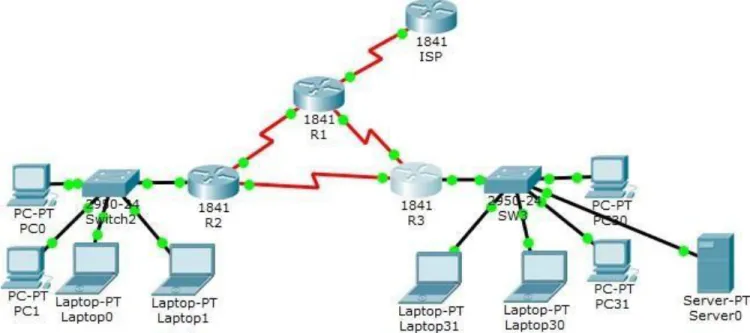
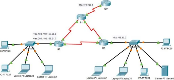
Escenario 1
En esta actividad, demostrará y reforzará su capacidad para implementar NAT,
servidor de DHCP, RIPV2 y el routing entre VLAN, incluida la configuración de
direcciones IP, las VLAN, los enlaces troncales y las subinterfaces. Todas las
pruebas de alcance deben realizarse a través de ping únicamente.
Ilustración 2. Ejercicio en Packet Tracer
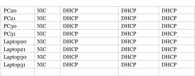
Tabla de direccionamiento
El
administrador Interfaces Dirección IP Máscara de subre d
Gateway predeterminad o
ISP S0/0/0 200.123.211.1 255.255.255.0 N/D
R1
Se0/0/0 200.123.211.2 255.255.255.0 N/D Se0/1/0 10.0.0.1 255.255.255.252 N/D Se0/1/1 10.0.0.5 255.255.255.252 N/D
R2
Fa0/0,100 192.168.20.1 255.255.255.0 N/D Fa0/0,200 192.168.21.1 255.255.255.0 N/D Se0/0/0 10.0.0.2 255.255.255.252 N/D Se0/0/1 10.0.0.9 255.255.255.252 N/D
R3 Fa0/0
SW2 VLAN 100 N/D N/D N/D
VLAN 200 N/D N/D N/D
SW3 VLAN1 N/D N/D N/D
PC20
NIC
DHCP
DHCP
DHCP
PC21
NIC
DHCP
DHCP
DHCP
PC30
NIC
DHCP
DHCP
DHCP
PC31
NIC
DHCP
DHCP
DHCP
Laptop20
NIC
DHCP
DHCP
DHCP
Laptop21
NIC
DHCP
DHCP
DHCP
Laptop30
NIC
DHCP
DHCP
DHCP
Laptop31
NIC
DHCP
DHCP
DHCP
Tabla de asignación de VLAN y de puertos
Dispositivo VLAN
Nombre
Interf
az
SW2
100
LAPTOPS
Fa0/2-3
SW2
200
DESTOPS
Fa0/4-5
SW3
1
-
Todas las interfaces
Tabla de enlaces troncales
Dispositivo
local
Interfaz
local
Dispositivo
remoto
SW2
Fa0/2-3
100
Configuración de los VLANS con sus respectivos nombres
Switch(config)#hostname SW2 SW2(config)#vlan 100
SW2(config-vlan) #name LAPTOPS SW2(config-vlan) #exit
SW2(config)#vlan 200
SW2(config-vlan) #name DESTOPS SW2(config-vlan) #end
SW2#
%SYS-5-CONFIG_I: Configured from console by console
Luego se asignan las VLAN a los puertos respectivos.
SW2#conf t
Enter configuration commands, one per line. End with CNTL/Z. SW2(config)#interface range f0/2-3
SW2(config-if-range)#switchport mode access SW2(config-if-range)#switchport access vlan 100 SW2(config-if-range)#exit
SW2(config)#interface range f0/4-5
SW2(config-if-range)#switchport mode access
SW2(config-if-range)#switchport access vlan 200 SW2(config-if-range)#end
SW2#
%SYS-5-CONFIG_I: Configured from console by console
Se deshabilitan los puertos que no se usan:
En le switch 2 y 3 se deshabilitan los puertos que no se usan
SW2(config)#interface range f0/6-24SW2(config-if-range)#shutdown
%LINK-5-CHANGED: Interface FastEthernet0/6, changed state to administratively down %LINK-5-CHANGED: Interface FastEthernet0/7, changed state to administratively down %LINK-5-CHANGED: Interface FastEthernet0/8, changed state to administratively down %LINK-5-CHANGED: Interface FastEthernet0/9, changed state to administratively down %LINK-5-CHANGED: Interface FastEthernet0/10, changed state to administratively down %LINK-5-CHANGED: Interface FastEthernet0/11, changed state to administratively down %LINK-5-CHANGED: Interface FastEthernet0/12, changed state to administratively down %LINK-5-CHANGED: Interface FastEthernet0/13, changed state to administratively down %LINK-5-CHANGED: Interface FastEthernet0/14, changed state to administratively down %LINK-5-CHANGED: Interface FastEthernet0/15, changed state to administratively down %LINK-5-CHANGED: Interface FastEthernet0/16, changed state to administratively down %LINK-5-CHANGED: Interface FastEthernet0/17, changed state to administratively down %LINK-5-CHANGED: Interface FastEthernet0/18, changed state to administratively down %LINK-5-CHANGED: Interface FastEthernet0/19, changed state to administratively down %LINK-5-CHANGED: Interface FastEthernet0/20, changed state to administratively down %LINK-5-CHANGED: Interface FastEthernet0/21, changed state to administratively down %LINK-5-CHANGED: Interface FastEthernet0/22, changed state to administratively down %LINK-5-CHANGED: Interface FastEthernet0/23, changed state to administratively down %LINK-5-CHANGED: Interface FastEthernet0/24, changed state to administratively down SW2(config-if-range)#
SW2#
%SYS-5-CONFIG_I: Configured from console by console SW3(config)#interface range f0/7-24
SW3(config-if-range)#shutdown
%LINK-5-CHANGED: Interface FastEthernet0/7, changed state to administratively down %LINK-5-CHANGED: Interface FastEthernet0/8, changed state to administratively down %LINK-5-CHANGED: Interface FastEthernet0/9, changed state to administratively down %LINK-5-CHANGED: Interface FastEthernet0/10, changed state to administratively down %LINK-5-CHANGED: Interface FastEthernet0/11, changed state to administratively down %LINK-5-CHANGED: Interface FastEthernet0/12, changed state to administratively down %LINK-5-CHANGED: Interface FastEthernet0/13, changed state to administratively down %LINK-5-CHANGED: Interface FastEthernet0/14, changed state to administratively down %LINK-5-CHANGED: Interface FastEthernet0/15, changed state to administratively down %LINK-5-CHANGED: Interface FastEthernet0/16, changed state to administratively down %LINK-5-CHANGED: Interface FastEthernet0/17, changed state to administratively down %LINK-5-CHANGED: Interface FastEthernet0/18, changed state to administratively down %LINK-5-CHANGED: Interface FastEthernet0/19, changed state to administratively down %LINK-5-CHANGED: Interface FastEthernet0/20, changed state to administratively down %LINK-5-CHANGED: Interface FastEthernet0/21, changed state to administratively down %LINK-5-CHANGED: Interface FastEthernet0/22, changed state to administratively down %LINK-5-CHANGED: Interface FastEthernet0/23, changed state to administratively down %LINK-5-CHANGED: Interface FastEthernet0/24, changed state to administratively down SW3(config-if-range)#end
SW3#
%SYS-5-CONFIG_I: Configured from console by console
Se crean las sub interfaces y se encapsulan asignándoles las
direcciones respectivas
R2(config)#interface f0/0.100
R2(config-subif)#encapsulation dot1Q 100
R2(config-subif)#ip address 192.168.20.1 255.255.255.0 R2(config-subif)#exit
R2(config)#interface f0/0.200
R2(config-subif)#encapsulation dot1Q 200
R2(config-subif)#ip address 192.168.21.1 255.255.255.0 R2(config-subif)#exit
Se excluyen las direcciones que se usaran para otros fines
R2(config)#ip dhcp excluded-address 192.168.20.1 192.168.20.10 R2(config)#ip dhcp excluded-address 192.168.21.1 192.168.21.10
Se crea el pool de direcciones para cada VLAN
R2(config)#ip dhcp pool vlan100
R2(dhcp-config)#network 192.168.20.0 255.255.255.0 R2(dhcp-config)#default-router 192.168.20.1
R2(dhcp-config)#exit
R2(config)#ip dhcp pool vlan200
R2(dhcp-config)#network 192.168.21.0 255.255.255.0 R2(dhcp-config)#default-router 192.168.21.1
R2(dhcp-config)#exit
Se sube la interface
R2(config)#interface f0/0 R2(config-if)#no shutdown
En el switch S2 se configura el enlace troncal
SW2(config)#interface f0/1
SW2(config-if)#switchport mode trunk
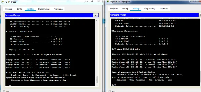
Ping entre PC20 que está en la VLAN100 y laptop 21 que está en VLAN200
Ilustración 5. Ping extremo a extremo
Configuración del router R3 para proporcionar direcciones IPV6 e IPV4
R3(config)#ip dhcp excluded-address 192.168.30.1 192.168.30.10 R3(config)#ip dhcp pool lista-pool
R3(dhcp-config)#network 192.168.30.0 255.255.255.0 R3(dhcp-config)#def
R3(dhcp-config)#default-router 192.168.30.1 R3(dhcp-config)#end
R3#
R3(config)#ipv6 unicast-routing R3(config)#interface f0/0 R3(config-if)#ipv6 enable
R3(config-if)#ip address 192.168.30.1 255.255.255.0 R3(config-if)#ipv6 address 2001:db8:130::9C0:80F:301/64 R3(config-if)#no shutdown
R3(config-if)#
%LINK-5-CHANGED: Interface FastEthernet0/0, changed state to up
Configuración para server DHCPipv6
R3#conf t
Enter configuration commands, one per line. End with CNTL/Z. R3(config)#ipv6 unicast-routing
R3(config)#ipv6 dhcp pool STATEFUL
R3(config-dhcpv6)#address prefix 2001:db8:130::9C0:80F:0/64 R3(config-dhcpv6)#exit
R3(config)#interface f0/0
R3(config-if)#ipv6 address 2001:db8:130::9C0:80F:301/64 R3(config-if)#ipv6 dhcp server STATEFUL
R3(config-if)#ipv6 nd managed-config-flag R3(config-if)#no shutdown
R3(config-if)#exit R3(config)#end R3#
%SYS-5-CONFIG_I: Configured from console by console
Configurando RIP versión 2 en R1, R2, R3
R2#conf t
Enter configuration commands, one per line. End with CNTL/Z. R2(config)#router rip
R2(config-router)#version 2 R2(config-router)#network 10.0.0.0 R2(config-router)#network 10.0.0.8 R2(config-router)#no auto-summary R2(config-router)#end
R2#
%SYS-5-CONFIG_I: Configured from console by console
R1#conf t
Enter configuration commands, one per line. End with CNTL/Z. R1(config)#router rip
R1(config-router)#version 2 R1(config-router)#network 10.0.0.0 R1(config-router)#network 10.0.0.4 R1(config-router)#no auto-summary R1(config-router)#end
R1#
%SYS-5-CONFIG_I: Configured from console by console R3#conf t
Enter configuration commands, one per line. End with CNTL/Z. R3(config)#router rip
R3(config-router)#end R3#
%SYS-5-CONFIG_I: Configured from console by console
Ping de extremo a extremo:
a.
Ping de extremo a extremo desde pc 20 vlan 100 a pc 30
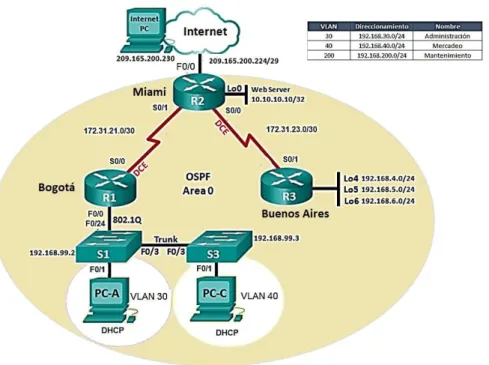
Escenario 2
Una empresa de Tecnología posee tres sucursales distribuidas en las ciudades de
Miami, Bogotá y Buenos Aires, en donde el estudiante será el administrador de la red,
el cual deberá configurar e interconectar entre sí cada uno de los dispositivos que
forman parte del escenario, acorde con los lineamientos establecidos para el
direccionamiento IP, protocolos de enrutamiento y demás aspectos que forman parte
de la topología de red.
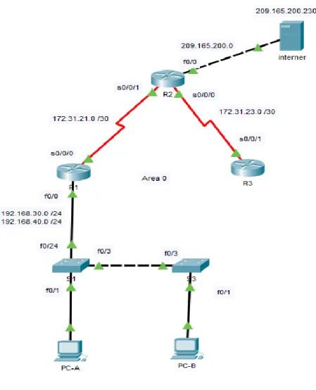
Ilustración 7. Ejercicio packet tracer
Se configuran las subinterfaces en R1
R1(config)#interface f0/0.30
R1(config-subif)#encapsulation dot1Q 30
R1(config-subif)#ip address 192.168.30.1 255.255.255.0 R1(config-subif)#exit
R1(config)#interface f0/0.40
R1(config-subif)#encapsulation dot1Q 40
R1(config-subif)#ip address 192.168.40.1 255.255.255.0 R1(config-subif)#exit
Se excluyen las primeras 30 direcciones que se usaran para otros fines
R1(config)#ip dhcp pool ADMINSTRACION
R1(dhcp-config)#NETwork 192.168.30.0 255.255.255.0 R1(dhcp-config)#dns-server 10.10.10.11
R1(dhcp-config)#domain-name ccna-unad.com R1(dhcp-config)#default-router 192.168.30.1 R1(dhcp-config)#exit
R1(config)#ip dhcp pool MERCADEO
R1(dhcp-config)#NETwork 192.168.40.0 255.255.255.0 R1(dhcp-config)#default-router 192.168.40.1
R1(dhcp-config)#dns-server 10.10.10.11 R1(dhcp-config)#domain-name ccna-unad.com R1(dhcp-config)#exit
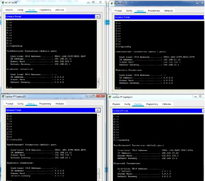
Se verifica que los pc tomen la configuración
Ilustración 8. Direccionamiento DHCP en los terminales
Se configura el protocolo de enrutamiento OSPFv2 bajo los siguientes criterios.
Configuration Item or Task
Specification
Router ID R1
1.1.1.1
Router ID R2
5.5.5.5
Router ID R3
8.8.8.8
Configurar todas las interfaces LAN como pasivas
Establecer el ancho de banda para enlaces
seriales en
256 Kb/s
R1(config)#router ospf 1
R1(config-router)#network 192.168.30.0 0.0.0.255 area 0
R1(config-router)#network 192.168.40.0 0.0.0.255 area 0
R1(config-router)#network 172.31.21.0 0.0.0.3 area 0
R1(config-router)#passive-interface f0/0
R1(config-router)#passive-interface f0/1
R1(config-router)#router-id 1.1.1.1
R1(config-router)#Reload or use "clear ip ospf process" command, for this to take effect
R1(config-router)#exit
R1(config)#exit
R1(config)#
En router 2
R2(config)#route ospf 2
R2(config-router)#network 172.31.21.0 0.0.0.3 area 0
R2(config-router)#network 209.165.200.0 0.0.0.255 area 0
R2(config-router)#router-id 5.5.5.5
R2(config-router)#Reload or use "clear ip ospf process" command, for this to take effect
R2(config-router)#end
En router 3
R3(config)#route ospf 3
R3(config-router)#network 172.31.21.0 0.0.0.3 area 0
R3(config-router)#network 192.168.4.0 0.0.0.255 area 0
R3(config-router)#network 192.168.5.0 0.0.0.255 area 0
R3(config-router)#network 192.168.6.0 0.0.0.255 area 0
R3(config-router)#router-id 8.8.8.8
R3(config-router)#Reload or use "clear ip ospf process" command, for this to take effect
R3(config-router)#end
En el Switch 3 deshabilitar DNS lookup
R3(config)#no ip domain-lookup
Verificar información de OSPF
Visualizar tablas de enrutamiento y routers conectados por OSPFv2
•
Visualizar el OSPF Process ID, Router ID, Address summarizations, Routing
Configuramos el servidor DHCP en R1
Configurar DHCP pool para VLAN 30
Name: ADMINISTRACION
DNS-Server: 10.10.10.11
Domain-Name: ccna-unad.com
Establecer default gateway.
Configurar DHCP pool para VLAN 40
Name: MERCADEO
DNS-Server: 10.10.10.11
Domain-Name: ccna-unad.com
Establecer default gateway.
R1(config)#ip dhcp pool ADMINSTRACION
R1(dhcp-config)#NETwork 192.168.30.0 255.255.255.0 R1(dhcp-config)#dns-server 10.10.10.11
R1(dhcp-config)#domain-name ccna-unad.com R1(dhcp-config)#default-router 192.168.30.1 R1(dhcp-config)#exit
R1(config)#ip dhcp pool MERCADEO
R1(dhcp-config)#NETwork 192.168.40.0 255.255.255.0 R1(dhcp-config)#default-router 192.168.40.1
R1(dhcp-config)#dns-server 10.10.10.11 R1(dhcp-config)#domain-name ccna-unad.com R1(dhcp-config)#exit
Donde ADMINISTRACION corresponde a vlan 30 y MERCADEO a vlan 40
Se excluyen las primeras 30 direcciones que se usaran para otros fines R1(config)#ip dhcp excluded-address 192.168.30.1 192.168.30.30
Se configura NAT en R2 para permitir que los hosts puedan salir a internet
R2#
R2#conf t
Enter configuration commands, one per line. End with CNTL/Z.
R2(config)#ip access-list standar MILISTA
R2(config-std-nacl)# permit 192.168.30.0 0.0.0.255
R2(config-std-nacl)# permit 192.168.40.0 0.0.0.255
R2#exit
R2(config)#ip nat pool 1 209.165.200.10 209.165.200.10 netmask 255.255.255.0
R2(config)#ip nat inside source MILISTA pool 1 overload
R2(config)#int f0/0
R2(config-if)#ip nat outside
R2(config-if)#exit
R2(config)#int s0/0/1
R2(config-if)#ip nat inside
R2(config-if)#exit
Conclusiones
- Se aplican los conocimientos adquiridos durante el curso como en el caso de la
configuración de vlan tablas de enrutamiento, direccionamiento IPV6 e IPV4
ente otros temas que son importantes a la hora de configurar una red.
- Se puede concluir que los dispositivos como router y switch de cisco
representan ventajas significativas a la hora de configurar una red donde se
requiere separar el tráfico para diferentes aplicaciones.
- Con estas prácticas se reforzaron los conceptos como enrutamiento OSPF, RIP
versión 2, configurar un servidor DHCP IPV4 o IPV6, configurar VLAN y
Bibliografía
Ariganello, E. (2008). Técnicas de configuración de routers CISCO. Madrid: Ra-Ma.
CCM. (2018). Configuración básica de un 'router' Cisco. [online] Recuperado de https://es.ccm.net/faq/2759-configuracion-basica-de-un-router-cisco.
Community.cisco.com. (2018). Como configurar un Switch Cisco Catalyst a través de sus
comandos. Recuperado de: https://community.cisco.com/t5/documentos-routing-y-switching/como-