DIPLOMADO DE PROFUNDIZACIÓN CISCO (DISEÑO E IMPLEMENTACIÓN DE SOLUCIONES INTEGRADAS LAN / WAN)
PRESENTADO POR:
LUIS FERNANDO JARAMILLO AYALA
UNIVERSIDAD NACIONAL ABIERTA Y A DISTANCIA - UNAD
ESCUELA DE CIENCIAS BÁSICAS, TECNOLOGÍA E INGENIERÍA
INGENIERIA DE SISTEMAS
PEREIRA RISARALDA
DICIEMBRE 2019
AUTOR LUIS FERNANDO JARAMILLO AYALA
TRABAJO DE GRADO DIPLOMADO DE PROFUNDIZACION CISCO
DIRECTOR DE CURSO
JUAN CARLOS VESGA
TUTOR
NILSON ALBEIRO FERREIRA MANZANARES
UNIVERSIDAD NACIONAL ABIERTA Y A DISTANCIA
ESCUELA DE CIENCIAS BÁSICAS, TECNOLOGÍA E INGENIERÍA.
INGENIERIA DE SISTEMAS
PEREIRA RISARALDA
Nota de Aceptación
___________________
___________________
___________________
____________________ Presidente del Jurado
____________________ Jurado
____________________ Jurado
Dedicatoria
Dedico este trabajo a Dios en agradecimiento por brindarme los recursos y todo lo necesario para culminar con mis estudios.
Agradezco a mi familia a mis directores y tutores de la universidad que fueron parte de mi formación siendo mi bastón de apoyo y orientación para culminar
exitosamente mis estudios. Toda la vida les recordare y quedare enormemente agradecido por Hacer de mí una mejor persona.
CONTENIDO
Pág.
INTRODUCCION……….………6.
1. OBJETIVOS ………7.
1.1 OBJETIVO GENERAL….. ………7.
1.2 OBJETIVOS ESPECÍFICOS………...7.
RESUMEN………...8.
ABSTRACT………...9.
TABLA DE ILUSTRACIONES………..………10.
DESARROLLO DE LOS ESCENARIOS………....12.
2. ESCENARIO 1………12.
2.1 PARTE 1: ASIGNACIÓN DE DIRECCIONES IP………..17.
2.2 PARTE 2: CONFIGURACIÓNÓN BÁSICA………18.
2.3 PARTE 3: CONFIGURACIÓN DE ENRUTAMIENTO………..22.
2.4 PARTE 4: CONFIGURACIÓN DE LAS LISTAS DE CONTROL DE ACCESO………..28.
2.5 PARTE 5: COMPROBACIÓN DE LA RED INSTALADA……….30.
3. ESCENARIO 2………39.
3.1 CONFIGURACIÓN BASICA……….41.
3.2 AUTENTICACIÓN LOCAL CON AAA……….…54.
3.3 CIFRADO DE CONTRASEÑAS………...56.
3.4 MÁXIMO DE INTERNOS PARA ACCEDER AL ROUTER….…………56
4. 6.5. MÁXIMO TIEMPO DE ACCESO AL DETECTAR ATAQUES………58.
5. CONCLUSIONES………...69.
6. REFERENCIAS BIBLIOGRAFICAS…….………...…70.
INTRODUCCIÓN
Con el desarrollo del presente trabajo abordaremos la construcción de una red de comunicación, la cual interconecta las ciudades de Bogotá, Medellín y Cali.
Con esto pondremos en práctica los conocimientos adquiridos en la solución de Problemas que se presentan en la vida real para cumplir y resolver las
necesidades de telecomunicación.
Como una solución a este problema empleamos el software de simulador de Packet Tracer. Para hacer efectiva la comunicación, se emplean routers y switchs, que en su función en conjunto soportan gran variedad de servicios de red,
permitiendo a los usuarios conectarse entre sí desde diferentes ciudades a la misma red, hay algunos servicios que se pueden restringir o desactivarse.
Lo cual mejora la seguridad de la red sin necesidad de que alguna operación de la red se vea afectada, por lo tanto, aunque esto represente un nivel de
OBJETIVOS
OBJETIVO GENERAL
Desarrollar la actividad final Prueba de habilidades prácticas CISCO CNNA2, con la cual se pretende en el ejercicio 1 realizar interconexiones entre las ciudades Bogotá, Medellín y Cali.
En el escenario 2 solucionar para una empresa que tiene conexión a internet en una red Ethernet, configurar sus routers y redes para que puedan conectarse a internet empleando las direcciones de la red LAN original.
OBJETIVOS ESPECÍFICOS
Desarrollar los ejercicios para conocer el debido funcionamiento de los routers en los enrutamientos dinámicos del tráfico.
Completar de manera exitosa la topología propuesta en la guía para el desarrollo de la actividad.
Establecer y comprobar la comunicación de los equipos mediante los comandos PING y TRACER.
RESUMEN
Con el desarrollo del presente trabajo, se da solución a la evaluación final da habilidades prácticas del curso CISCO CCNA 2. El ejercicio consta de 2 escenarios:
Escenario 1: Una empresa posee sucursales distribuidas en las ciudades de Bogotá, Medellín y Cali en donde el estudiante será el administrador de la red, el cual deberá configurar e interconectar entre sí cada uno de los dispositivos que forman parte del escenario, acorde con los lineamientos establecidos para el direccionamiento IP, protocolos de enrutamiento y demás aspectos que forman parte de la topología de red.
ABSTRACT
With the development of this work, the final evaluation of the practical skills of the CISCO CCNA 2 course is given the exercise consists of 2 scenarios:
Scenario 1: A company has branches distributed in the cities of Bogotá, Medellin and Cali where the student will be the network administrator, who must configure and interconnect each of the devices that are part of the scenario, according to the established guidelines for IP addressing, routing protocols and other aspects that are part of the network topology.
TABLA DE ILUSTRACIONES
Pág
Ilustración 1. Topología de la red ... 13
Ilustración 2. diagnóstico de vecinos usando el comando cdp ... 22
Ilustración 3. diagnóstico de vecinos usando el comando cdp... 23
Ilustración 4. Ping de Medellín a Bogotá ... 23
Ilustración 5. Ping desde Cali hacia Bogotá ... 24
Ilustración 6. Ping de Cali a Medellín y router verificando conectividad. ... 28
Ilustración 7. Se verifica conexiones Telnet con los demás routers ... 31
Ilustración 8. Telnet desde Servidor a router Bogotá. ... 32
Ilustración 9. Telnet desde Bogotá a Medellín. ... 33
Ilustración 10. Telnet desde Cali a Bogotá... 33
Ilustración 11. se realiza ping desde el servidor y switch 1 ... 34
Ilustración 12. se verifica conectividad desde pc3 a LAN Medellín, Cali y hacia el servidor. ... 37
Ilustración 13. se verifica conectividad desde pc0 a LAN Medellín, Cali y hacia el servidor ... 38
Ilustración 14. Topología de red escenario 2... 40
Ilustración 15. Conexión de los equipos ... 48
Ilustración 16. Activación servicio TFTP ... 56
Ilustración 17. PING conexión a internet desde PC4 VLAN 30 LAN del router Cundinamarca a Servidor Web Externo y a PC12 VLAN20 LAN del router Tunja ... 57
Ilustración 18. ping conexión a internet desde PC5 VLAN 30 LAN del router Cundinamarca a Servidor Web Externo y a PC12 VLAN20 LAN del router Tunja ... 57
Ilustración 19. ping desde PC3 VLAN30 LAN del router Tunja a Servidor Web ... 58
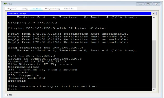
Ilustración 20. prueba de conexión FTP de internet ... 58
Ilustración 21. ping desde PC2 VLAN 20 LAN del router Tunja a PC10 VLAN10 LAN del router Bucaramanga y a PC15 VLAN20 LAN del router Cundinamarca .. 59
Ilustración 22. ping desde PC2 VLAN 20 LAN del router Tunja a PC15 VLAN20 LAN del router Cundinamarca ... 60
Ilustración 23. ping desde PC1 VLAN30 LAN de router Bucaramanga a PC14 VLAN20 LAN del router Cundinamarca y a PC12 VLAN20 LAN del router Tunja ... 61
Ilustración 24. PING desde PC0 VLAN10 LAN del router Bucaramanga a PC14 VLAN20 LAN del router Cundinamarca... 62
Ilustración 27. ping desde PC14 VLAN10 LAN del router Cundinamarca a PC15 VLAN20 LAN del router Cundinamarca ... 65 Ilustración 28. se realiza telnet desde SWITCH Bucaramanga a router Tunja ... 67 Ilustración 29. se realiza telnet desde SWITCH Cundinamarca a router
DESARROLLO DE LOS ESCENARIOS
Escenario 1
Una empresa posee sucursales distribuidas en las ciudades de Bogotá, Medellín y Cali en donde el estudiante será el administrador de la red, el cual deberá
configurar e interconectar entre sí cada uno de los dispositivos que forman parte del escenario, acorde con los lineamientos establecidos para el direccionamiento IP, protocolos de enrutamiento y demás aspectos que forman parte de la topología de red.
Topología de red
Los requerimientos solicitados son los siguientes:
Parte 1: Para el direccionamiento IP debe definirse una dirección de acuerdo con el número de hosts requeridos.
Parte 2: Considerar la asignación de los parámetros básicos y la detección de vecinos directamente conectados.
Parte 3: La red y subred establecidas deberán tener una interconexión total, todos los hosts deberán ser visibles y poder comunicarse entre ellos sin restricciones.
Parte 4: Implementar la seguridad en la red, se debe restringir el acceso y
Parte 5: Comprobación total de los dispositivos y su funcionamiento en la red.
Parte 6: Configuración final.
ILUSTRACION 1: TOPOLOGIA DE LA RED
Desarrollo
Como trabajo inicial se debe realizar lo siguiente.
Realizar las rutinas de diagnóstico y dejar los equipos listos para su configuración (asignar nombres de equipos, asignar claves de seguridad, etc.).
Realizar la conexión física de los equipos con base en la topología de red Configurar la topología de red, de acuerdo con las siguientes especificaciones
Parte 1: Asignación de direcciones IP:
Se configura los routers con el comando ip route Router>en Router#conf t
Enter configuration commands, one per line. End with CNTL/Z.
if)#ip address 192.168.1.1 255.255.255.224 BOGOTA(config-if)#no shutdown
BOGOTA(config-if)#
%LINK-5-CHANGED: Interface FastEthernet0/0, changed state to up
%LINEPROTO-5-UPDOWN: Line protocol on Interface FastEthernet0/0, changed state to up
BOGOTA(config-if)#exit BOGOTA(config)#int s0/0 BOGOTA(config-if)#192.168.1.98 255.255.255.224 ^
% Invalid input detected at '^' marker.
if)#ip address 192.168.1.98 255.255.255.224 BOGOTA(config-if)#no shutdown
%LINK-5-CHANGED: Interface Serial0/0, changed state to down BOGOTA(config-if)#no shutdown
BOGOTA(config-if)#exit BOGOTA(config)#interface serial0/1
if)#ip address 192.168.1.130 255.255.255.224 BOGOTA(config-if)#no shutdown
%LINK-5-CHANGED: Interface Serial0/1, changed state to down BOGOTA(config-if)#exit
BOGOTA(config)#end BOGOTA#
%SYS-5-CONFIG_I: Configured from console by console
BOGOTA#enable BOGOTA#config terminal
Enter configuration commands, one per line. End with CNTL/Z.
BOGOTA(config)#ip route 192.168.1.64 255.255.255.224 192.168.1.131 BOGOTA(config)#ip route 192.168.1.32 255.255.255.224 192.168.1.99 BOGOTA(config)#exit BOGOTA#
%SYS-5-CONFIG_I: Configured from console by console
BOGOTA#copy running-config startup-config Destination filename [startup-config]? Building configuration... [OK]
BOGOTA#
%LINK-5-CHANGED: Interface Serial0/0, changed state to up
%LINEPROTO-5-UPDOWN: Line protocol on Interface Serial0/0, changed state to up
BOGOTA#
Router>enable Router#config terminal
Enter configuration commands, one per line. End with CNTL/Z.
MEDELLIN(config-if)#no shutdown
MEDELLIN(config-if)#
%LINK-5-CHANGED: Interface FastEthernet0/0, changed state to up
%LINEPROTO-5-UPDOWN: Line protocol on Interface FastEthernet0/0, changed state to up
MEDELLIN(config-if)#exit MEDELLIN(config)#interface s0/0 MEDELLIN(config-if)#ip address 192.168.1.99 255.255.255.224 MEDELLIN(config-if)#no shutdown
MEDELLIN(config-if)#
%LINK-5-CHANGED: Interface Serial0/0, changed state to up
MEDELLIN(config-if)#
%LINEPROTO-5-UPDOWN: Line protocol on Interface Serial0/0, changed state to up
MEDELLIN(config-if)#exit MEDELLIN(config)#end MEDELLIN#
%SYS-5-CONFIG_I: Configured from console by console
MEDELLIN#enable MEDELLIN#config terminal
Enter configuration commands, one per line. End with CNTL/Z.
MEDELLIN(config)#ip route 192.168.1.0 255.255.255.224 192.168.1.97 MEDELLIN(config)#ip route 192.168.1.64 255.255.255.224 192.168.1.97 MEDELLIN(config)#exit MEDELLIN#
%SYS-5-CONFIG_I: Configured from console by console
MEDELLIN#copy running-config startup-config Destination filename [startup-config]?
Building configuration... [OK] MEDELLIN#
Router>enable Router#config terminal
Enter configuration commands, one per line. End with CNTL/Z. Router(config)#hostname CALI
CALI(config)#interface fastetheret0/0 ^
CALI(config-if)#
%LINK-5-CHANGED: Interface FastEthernet0/0, changed state to up
%LINEPROTO-5-UPDOWN: Line protocol on Interface FastEthernet0/0, changed state to up
CALI(config-if)#exit CALI(config)#interface s0/0
CALI(config-if)#ip address 192.168.1.131 255.255.255.224 CALI(config-if)#no shutdown
CALI(config-if)#
%LINK-5-CHANGED: Interface Serial0/0, changed state to up
CALI(config-if)#exit CALI(config)#
%LINEPROTO-5-UPDOWN: Line protocol on Interface Serial0/0, changed state to up
CALI(config)#end CALI#
%SYS-5-CONFIG_I: Configured from console by console
CALI#enable CALI#config terminal
Enter configuration commands, one per line. End with CNTL/Z. CALI(config)#ip route 192.168.1.0 255.255.255.224 192.168.1.129
CALI(config)#ip route 192.168.1.32 255.255.255.224 192.168.1.129 CALI(config)#exit CALI#
%SYS-5-CONFIG_I: Configured from console by console
CALI#copy running-config startup-config Destination filename [startup-config]? Building configuration... [OK]
CALI#
Se debedividir (subnetear) lared creando unasegmentación en ocho partes, para permitir crecimiento futuro de la red corporativa.
R/ se utiliza la red como es sugerido y se divide en 8 partes, cada una en la red /27 con una máscara de sub red que pertenece a //27, es 255.255.255.2224
192.168.1.0/27
192.168.1.32/27
192.168.1.64/27
192.168.1.128/27
192.168.1.160/27
192.168.1.192/27
192.168.1.224/27
Asignar una dirección IP a lared.
Dirección ip: 192.168.1.0/24
Parte 2: Configuración Básica.
Completar la siguiente tabla con la configuración básica de los routers, teniendo en cuenta las subredes diseñadas.
R1 R2 R3
Nombre de Host MEDELLIN BOGOTA CALI
Dirección deIpen interfaz Serial0/0
192.168.1.99 192.168.1.98 192.168.1.1 1
Dirección de Ip en interfaz Serial 0/1
192.168.1.130
Dirección de Ip en interfaz FA 0/0
192.168.1.3 3
192.168.1.1 192.168.1.6
Protocolo de enrutamiento Eigrp Eigrp Eigrp
Sistema Autónomo 200 200 200
Afirmaciones de red 192.168.1.0 192.168.1.0 192.168.1.0
Se asignan contraseñas
BOGOTA>enable BOGOTA#config terminal
Enter configuration commands, one per line. End with CNTL/Z. BOGOTA(config)#enable secret cisco
BOGOTA(config)#line consol 0 BOGOTA(config-line)#password lucho10 BOGOTA(config-line)#login BOGOTA(config-line)#exit
MEDELLIN>enable MEDELLIN#config terminal
Enter configuration commands, one per line. End with CNTL/Z.
MEDELLIN(config)#enable secret cisco MEDELLIN(config)#line consol 0 MEDELLIN(config-line)#password lucho10 MEDELLIN(config-line)#login MEDELLIN(config-line)#exit
CALI>enable CALI#config terminal
Enter configuration commands, one per line. End with CNTL/Z. CALI(config)# enable secret cisco
CALI(config)#line consol 0 line)#password lucho10 CALI(config-line)#login
CALI(config-line)#exit CALI(config)# CALI(config)#exit
CONFIGURANDO LOS ROUTERS PARA EL LINE VTY 0 4
BOGOTA>enable Password: Password:
BOGOTA#config terminal
Enter configuration commands, one per line. End with CNTL/Z. BOGOTA(config)#line vty 0 4
BOGOTA(config-line)#password cisco10 BOGOTA(config-line)#login BOGOTA(config-line)#loggin synchronous BOGOTA(config-line)#exit BOGOTA(config)#
MEDELLIN>enable Password: MEDELLIN#config terminal
Enter configuration commands, one per line. End with CNTL/Z. MEDELLIN(config)#line vty 0 4
MEDELLIN(config-line)#password cisco10 MEDELLIN(config-line)#login MEDELLIN(config-line)#loggin synchronous MEDELLIN(config-line)#exit
CALI>enable Password: CALI#config terminal
Enter configuration commands, one per line. End with CNTL/Z. CALI(config)#line vty 0 4
CALI(config-line)#password cisco10 CALI(config-line)#login CALI(config-line)#loggin synchronous CALI(config-line)#exit
Después de cargada la configuración en los dispositivos, verificar la tabla de enrutamiento en cada uno de los routers para comprobar las redes y sus rutas.
BOGOTA>enable Password: BOGOTA#show ip route
Codes: C - connected, S - static, I - IGRP, R - RIP, M - mobile, B - BGP D - EIGRP, EX - EIGRP external, O - OSPF, IA - OSPF inter area
i - IS-IS, L1 - IS-IS level-1, L2 - IS-IS level-2, ia - IS-IS inter area
- candidate default, U - per-user static route, o - ODR P - periodic downloaded static route
Gateway of last resort is not set 192.168.1.0/27 is subnetted, 5 subnets C 192.168.1.0 is directly connected, FastEthernet0/0
D 192.168.1.32 [90/2172416] via 192.168.1.99, 05:26:26, Serial0/0 D 192.168.1.64 [90/2172416] via 192.168.1.131, 05:26:23, Serial0/1 C 192.168.1.96 is directly connected, Serial0/0 C 192.168.1.128 is directly connected, Serial0/1
MEDELLIN>enable Password: MEDELLIN#show ip route
Codes: C - connected, S - static, I - IGRP, R - RIP, M - mobile, B - BGP D - EIGRP, EX - EIGRP external, O - OSPF, IA - OSPF inter area
N1 - OSPF NSSA external type 1, N2 - OSPF NSSA external type 2 E1 - OSPF external type 1, E2 - OSPF external type 2, E - EGP
i - IS-IS, L1 - IS-IS level-1, L2 - IS-IS level-2, ia - IS-IS inter area
- candidate default, U - per-user static route, o - ODR P - periodic downloaded static route
Gateway of last resort is not set 192.168.1.0/27 is subnetted, 5 subnets D 192.168.1.0 [90/2172416] via 192.168.1.98, 05:31:25, Serial0/0 C 192.168.1.32 is directly connected, FastEthernet0/0
D 192.168.1.64 [90/2684416] via 192.168.1.98, 05:31:22, Serial0/0 C 192.168.1.96 is directly connected, Serial0/0
D 192.168.1.128 [90/2681856] via 192.168.1.98, 05:31:25, Serial0/0
CALI>enable Password: CALI#show ip route
Codes: C - connected, S - static, I - IGRP, R - RIP, M - mobile, B - BGP D - EIGRP, EX - EIGRP external, O - OSPF, IA - OSPF inter area
N1 - OSPF NSSA external type 1, N2 - OSPF NSSA external type 2 E1 - OSPF external type 1, E2 - OSPF external type 2, E - EGP
i - IS-IS, L1 - IS-IS level-1, L2 - IS-IS level-2, ia - IS-IS inter area
- candidate default, U - per-user static route, o - ODR P - periodic downloaded static route
D 192.168.1.32 [90/2684416] via 192.168.1.130, 05:32:24, Serial0/0 C 192.168.1.64 is directly connected, FastEthernet0/0
D 192.168.1.96 [90/2681856] via 192.168.1.130, 05:32:24, Serial0/0 C 192.168.1.128 is directly connected, Serial0/0
Verificar el balanceo de carga que presentan los routers. MEDELLIN MEDELLIN>en
Password:
MEDELLIN#show ip eigrp topology
IP-EIGRP Topology Table for AS 1/ID(192.168.1.99)
Codes: P - Passive, A - Active, U - Update, Q - Query, R - Reply, r - Reply status
P 192.168.1.0/27, 1 successors, FD is 2172416 via 192.168.1.98 (2172416/28160), Serial0/0
P 192.168.1.32/27, 1 successors, FD is 28160 via Connected, FastEthernet0/0 P 192.168.1.64/27, 1 successors, FD is 2684416 via 192.168.1.98
(2684416/2172416), Serial0/0
P 192.168.1.96/27, 1 successors, FD is 2169856 via Connected, Serial0/0 P 192.168.1.128/27, 1 successors, FD is 2681856 via 192.168.1.98
(2681856/2169856), Serial0/0
BOGOTA BOGOTA>en Password:
BOGOTA#show ip eigrp topology
IP-EIGRP Topology Table for AS 1/ID(192.168.1.130)
Codes: P - Passive, A - Active, U - Update, Q - Query, R - Reply, r - Reply status
P 192.168.1.0/27, 1 successors, FD is 28160 via Connected, FastEthernet0/0 P 192.168.1.32/27, 1 successors, FD is 2172416 via 192.168.1.99
(2172416/28160), Serial0/0
P 192.168.1.64/27, 1 successors, FD is 2172416 via 192.168.1.131 (2172416/28160), Serial0/1
via Connected, Serial0/1 CALI CALI>en
Password:
CALI#show ip eigrp topology
IP-EIGRP Topology Table for AS 1/ID(192.168.1.131)
Codes: P - Passive, A - Active, U - Update, Q - Query, R - Reply, r - Reply status
P 192.168.1.0/27, 1 successors, FD is 2172416 via 192.168.1.130 (2172416/28160), Serial0/0
P 192.168.1.32/27, 1 successors, FD is 2684416 via 192.168.1.130 (2684416/2172416), Serial0/0
P 192.168.1.64/27, 1 successors, FD is 28160 via Connected, FastEthernet0/0 P 192.168.1.96/27, 1 successors, FD is 2681856 via 192.168.1.130
(2681856/2169856), Serial0/0
P 192.168.1.128/27, 1 successors, FD is 2169856 via Connected, Serial0/0
ILUSTRACION 3: Realizar un diagnóstico de vecinos usando el comando cdp.
Realizar una prueba de conectividad en cada tramo de la ruta usando Ping.
ILUSTRACION 5: Se realiza ping de Cali hacia Bogotá
Parte 3: Configuración de Enrutamiento.
Asignar el protocolo de enrutamiento EIGRP a los routers considerando el direccionamiento diseñado.
BOGOTA>en BOGOTA#conf t
Enter configuration commands, one per line. End with CNTL/Z. BOGOTA(config)#router eigrp 1
BOGOTA(config-router)#no auto-summary BOGOTA(config-router)#network 192.168.1.96
BOGOTA(config-router)#network 192.168.1.0
BOGOTA(config-router)#network 192.168.1.128 BOGOTA(config-router)#end
MEDELLIN>en MEDELLIN#conf t
Enter configuration commands, one per line. End with CNTL/Z. MEDELLIN(config)#router eigrp 1
MEDELLIN(config-router)#no auto-summary MEDELLIN(config-router)#network 192.168.1.32 Router(config-router)#
new adjacency
MDELLIN(config-router)#network 192.168.1.32
MEDELLIN(config-router)#network 192.168.1.96 MEDELLIN(config-router)#end
CALI>en
CALI#config terminal
Enter configuration commands, one per line. End with CNTL/Z. CALI(config)#router eigrp 1
CALI(config-router)#no auto-summary CALI(config-router)#network 192.168.1.128 Router(config-router)#
%DUAL-5-NBRCHANGE: IP-EIGRP 1: Neighbor 192.168.1.130 (Serial0/0) is up: new adjacency
CALI(config-router)#network 192.168.1.128
CALI(config-router)#network 192.168.1.64 CALI(config-router)#end CALI#
Verificar si existe vecindad con los routers configurados con EIGRP.
MEDELLIN>en Password:
MEDELLIN#show ip eigrp neighbors IP-EIGRP neighbors for process 1 H Address Interface Hold Uptime SRTT RTO Q Seq (sec) (ms) Cnt Num 0 192.168.1.98 Se0/0 14 05:52:02 40 1000 0 5
CALI>enable Password: CALI#show ip eigrp neighbors IP-EIGRP neighbors for process 1
H Address Interface Hold Uptime SRTT RTO Q Seq (sec) (ms) Cnt Num 0 192.168.1.130 Se0/0 14 05:53:03 40 1000 0 6
BOGOTA>enable Password:
1 192.168.1.131 Se0/1 14 05:46:23 40 1000 0 7
Realizar la comprobación de las tablas de enrutamiento en cada uno de los routers para verificar cada una de las rutas establecidas.
MEDELLIN>en Password:
MEDELLIN#show ip route
Codes: C - connected, S - static, I - IGRP, R - RIP, M - mobile, B - BGP D - EIGRP, EX - EIGRP external, O - OSPF, IA - OSPF inter area
N1 - OSPF NSSA external type 1, N2 - OSPF NSSA external type 2 E1 - OSPF external type 1, E2 - OSPF external type 2, E - EGP
i - IS-IS, L1 - IS-IS level-1, L2 - IS-IS level-2, ia - IS-IS inter area
- candidate default, U - per-user static route, o - ODR P - periodic downloaded static route
Gateway of last resort is not set 192.168.1.0/27 is subnetted, 5 subnets D 192.168.1.0 [90/2172416] via 192.168.1.98, 06:05:58, Serial0/0 C 192.168.1.32 is directly connected, FastEthernet0/0
D 192.168.1.64 [90/2684416] via 192.168.1.98, 06:05:55, Serial0/0 C 192.168.1.96 is directly connected, Serial0/0
D 192.168.1.128 [90/2681856] via 192.168.1.98, 06:05:58, Serial0/0
BOGOTA>enable Password: BOGOTA#show ip route
Codes: C - connected, S - static, I - IGRP, R - RIP, M - mobile, B - BGP D - EIGRP, EX - EIGRP external, O - OSPF, IA - OSPF inter area
N1 - OSPF NSSA external type 1, N2 - OSPF NSSA external type 2 E1 - OSPF external type 1, E2 - OSPF external type 2, E - EGP
i - IS-IS, L1 - IS-IS level-1, L2 - IS-IS level-2, ia - IS-IS inter area
- candidate default, U - per-user static route, o - ODR P - periodic downloaded static route
Gateway of last resort is not set 192.168.1.0/27 is subnetted, 5 subnets C 192.168.1.0 is directly connected, FastEthernet0/0
CALI>enable Password: CALI#show ip route
Codes: C - connected, S - static, I - IGRP, R - RIP, M - mobile, B - BGP D - EIGRP, EX - EIGRP external, O - OSPF, IA - OSPF inter area
N1 - OSPF NSSA external type 1, N2 - OSPF NSSA external type 2 E1 - OSPF external type 1, E2 - OSPF external type 2, E - EGP
i - IS-IS, L1 - IS-IS level-1, L2 - IS-IS level-2, ia - IS-IS inter area
- candidate default, U - per-user static route, o - ODR P - periodic downloaded static route
Gateway of last resort is not set 192.168.1.0/27 is subnetted, 5 subnets D 192.168.1.0 [90/2172416] via 192.168.1.130, 06:07:48, Serial0/0 D 192.168.1.32 [90/2684416] via 192.168.1.130, 06:07:48, Serial0/0 C 192.168.1.64 is directly connected, FastEthernet0/0
D 192.168.1.96 [90/2681856] via 192.168.1.130, 06:07:48, Serial0/0 C 192.168.1.128 is directly connected, Serial0/0
ILUSTRACION 6: se realiza ping de cali a medellin y router verificando conectividad.
Parte 4: Configuración de las listas de Control de Acceso.
En este momento cualquier usuario de la red tiene acceso a todos sus dispositivos y estaciones de trabajo. El jefe de redes le solicita implementar seguridad en la red. Para esta labor se decide configurar listas de control de acceso (ACL) a los
routers.
Las condiciones para crear las ACL son las siguientes:
Se realiza la configuracion de las acl permitimos solo el acceso hacia el servidor
MEDELLIN>enable Password:
MEDELLIN#configure terminal
Enter configuration commands, one per line. End with CNTL/Z. MEDELLIN(config)#ip access-list extended ServerPT
MEDELLIN(config-ext-nacl)#permit ip 0.0.0.0 255.255.255.255 192.168.1.3 0.0.0.0 MEDELLIN(config-ext-nacl)#exit MEDELLIN(config)#interface fa0/0
CALI>enable Password: CALI#config terminal
Enter configuration commands, one per line. End with CNTL/Z. CALI(config)#ip access-list extended ServerPT
CALI(config-ext-nacl)#permit ip 0.0.0.0 255.255.255.255 192.168.1.3 0.0.0.0 CALI(config-ext-nacl)#exit
CALI(config)#int fa0/0
CALI(config-if)#ip access-group ServerPT in CALI(config-if)#end
BOGOTA>enable Password:
BOGOTA#config terminal Enter configuration co
mmands, one per line. End with CNTL/Z. BOGOTA(config)#ip access-list extended ServerPT
BOGOTA(config-ext-nacl)#permit ip 192.168.1.3 0.0.0.0 0.0.0.0 255.255.255.255 ext-nacl)#exit BOGOTA(config)#interface fa0/0 BOGOTA(config-if)#ip access-group ServerPT in BOGOTA(config-if)#end
A continuación permitimos que los routers accedan a los equipos: User Access Verification
Password:
MEDELLIN>enable Password: MEDELLIN#config terminal
Enter configuration commands, one per line. End with CNTL/Z. MEDELLIN(config)#ip access-list extended ServerPT
MEDELLIN(config-ext-nacl)#permit ip 0.0.0.0 255.255.255.255 192.168.1.33 0.0.0.0
MEDELLIN(config-ext-nacl)#permit ip 0.0.0.0 255.255.255.255 192.168.1.98 0.0.0.0
MEDELLIN(config-ext-nacl)#permit ip 0.0.0.0 255.255.255.255 192.168.1.131 0.0.0.0
MEDELLIN(config-ext-nacl)#end
BOGOTA#
BOGOTA#config terminal
Enter configuration commands, one per line. End with CNTL/Z. BOGOTA(config)#ip access-list extended ServerPT
BOGOTA(config-ext-nacl)#permit ip 0.0.0.0 255.255.255.255 192.168.1.99 0.0.0.0 BOGOTA(config-ext-nacl)#permit ip 0.0.0.0 255.255.255.255 192.168.1.1 0.0.0.0 BOGOTA(config-ext-nacl)#permit ip 0.0.0.0 255.255.255.255 192.168.1.131 0.0.0.0
User Access Verification Password: CALI>enable Password:
Password:
CALI#config terminal
Enter configuration commands, one per line. End with CNTL/Z. CALI(config)#ip access-list extended ServerPT
CALI(config-ext-nacl)#permit ip 0.0.0.0 255.255.255.255 192.168.1.99 0.0.0.0 CALI(config-ext-nacl)#permit ip 0.0.0.0 255.255.255.255 192.168.1.1 0.0.0.0 CALI(config-ext-nacl)#permit ip 0.0.0.0 255.255.255.255 192.168.1.65 0.0.0.0 CALI(config-ext-nacl)#end CALI#
Cada router debe estar habilitado para establecer conexiones Telnet con los demás routers y tener acceso a cualquier dispositivo en la red.
ILUSTRACION 10: se verifica conexiones telnet con los demás routers
Según los requerimientos nos solicitan que los puntos hagan ping y para eso debemos quitar las acl y el listado, por lo tanto se anula el comando para poder tener conectividad de nuevo.
BOGOTA>en Password: BOGOTA#conf t
Enter configuration commands, one per line. End with CNTL/Z. BOGOTA(config)#int fa0/0
CALI>enable Password: CALI#conf t
Enter configuration commands, one per line. End with CNTL/Z. CALI(config)#int fa0/0
CALI(config-if)#no ip access-group ServerPT in CALI(config-if)#end
MEDELLIN>enable Password: MEDELLIN#config terminal
Enter configuration commands, one per line. End with CNTL/Z. MEDELLIN(config)#interface fa0/0
MEDELLIN(config-if)#no ip access-group ServerPT in MEDELLIN(config-if)#end
El equipo WS1 y el servidor se encuentran en la subred de administración. Solo el servidor de la subred de administración debe tener acceso a cualquier otro dispositivo en cualquier parte de la red.
ILUSTRACION 11: se realiza ping desde el servidor y switch 1
MEDELLIN>ena Password:
Enter configuration commands, one per line. End with CNTL/Z. MEDELLIN(config)#ip access-list extended ServerPT
MEDELLIN(config-ext-nacl)#permit ip 0.0.0.0 255.255.255.255 192.168.1.33 0.0.0.0
MEDELLIN(config-ext-nacl)#permit ip 0.0.0.0 255.255.255.255 192.168.1.98 0.0.0.0
MEDELLIN(config-ext-nacl)#permit ip 0.0.0.0 255.255.255.255 192.168.1.131 0.0.0.0
MEDELLIN(config-ext-nacl)#end
BOGOTA#conf t
Enter configuration commands, one per line. End with CNTL/Z. BOGOTA(config)#ip access-list extended ServerPT
BOGOTA(config-ext-nacl)#permit ip 0.0.0.0 255.255.255.255 192.168.1.99 0.0.0.0 BOGOTA(config-ext-nacl)#permit ip 0.0.0.0 255.255.255.255 192.168.1.1 0.0.0.0 BOGOTA(config-ext-nacl)#permit ip 0.0.0.0 255.255.255.255 192.168.1.131 0.0.0.0
BOGOTA(config-ext-nacl)#end
CALI>ena Password: Password:
CALI#confi t
Enter configuration commands, one per line. End with CNTL/Z. CALI(config)#ip access-list extended ServerPT
Las estaciones de trabajo en las LAN de MEDELLIN y CALI no deben tener acceso a ningún dispositivo fuera de su subred, excepto para interconectar con el servidor.
Parte 5: Comprobación de la red instalada.
Se debe probar que la configuración de las listas de acceso fue exitosa. Comprobar y Completar la siguiente tabla de condiciones de prueba para confirmar el óptimo funcionamiento de la red.
ORIGE N DESTIN O RESULTADO
Router MEDELLIN Router CALI Éxito Falla Éxito Éxito Falla Falla Falla Falla Falla Falla Falla Falla Falla Falla Falla Éxito Éxito Éxito Éxito Éxito Éxito Éxito Falla Falla Falla
TELNET WS_1 Router BOGOTA
d Servidor Router CALI
Servidor Router MEDELLIN LAN del Router
MEDELLIN
Router CALI
TELNET LAN del Router CALI Router CALI LAN del Router
MEDELLIN
Router MEDELLIN
LAN del Router CALI Router MEDELLIN LAN del Router CALI WS_1
PING LAN del Router MEDELLIN
WS_1
LAN del Router MEDELLIN
LAN del Router CALI
LAN del Router CALI Servidor LAN del Router
MEDELLIN
Servidor
PING Servidor LAN del Router MEDELLIN
Servidor LAN del Router CALI Router CALI LAN del Router
MEDELLIN
Escenario 2
Ilustración 14: topología de la red escenario 2
Una empresa tiene la conexión a internet en una red Ethernet, lo cual deben adaptarlo para facilitar que sus routers y las redes que incluyen puedan, por esa vía, conectarse a internet, pero empleando las direcciones de la red LANoriginal.
Desarrollo
Los siguientes son los requerimientos necesarios: Todos los routers deberán tener lossiguiente: Configuración básica.
Router>enable Router#conf t
Enter configuration commands, one per line. End with CNTL/Z.
Router(config)#hostname BUCARAMANGA BUCARAMANGA(config)#no ip domain-lookup BUCARAMANGA(config)#banner motd #Cuidado Acceso Restringido# BUCARAMANGA(config)#enable secret class123
BUCARAMANGA(config)#line console 0
line)#logging synchronous BUCARAMANGA(config-line)#line vty 0 15 BUCARAMANGA(config-line)#password cisco123
BUCARAMANGA(config-line)#login BUCARAMANGA(config-line)#logging synchronous BUCARAMANGA(config)#int f0/0.1 BUCARAMANGA(config-subif)#encapsulation dot1q 1
BUCARAMANGA(config-subif)#ip address 172.31.2.1 255.255.255.248 BUCARAMANGA(config-subif)#int f0/0.10
BUCARAMANGA(config-subif)#encapsulation dot1q 10
BUCARAMANGA(config-subif)#ip address 172.31.0.1 255.255.255.192 BUCARAMANGA(config-subif)#int f0/0.30
BUCARAMANGA(config-subif)#encapsulation dot1q 30
BUCARAMANGA(config-subif)#ip address 172.31.0.65 255.255.255.192 BUCARAMANGA(config-subif)#int f0/0
BUCARAMANGA(config-if)#no shutdown
BUCARAMANGA(config-if)# BUCARAMANGA(config-if)# BUCARAMANGA(config-if)#int s0/0/0
BUCARAMANGA(config-if)#ip address 172.31.2.34 255.255.255.252 BUCARAMANGA(config-if)#no shutdown
%LINK-5-CHANGED: Interface Serial0/0/0, changed state to down BUCARAMANGA(config-if)#
BUCARAMANGA(config-if)#router ospf 1
BUCARAMANGA(config-router)#network 172.31.0.0 0.0.0.63 area 0 BUCARAMANGA(config-router)#network 172.31.0.64 0.0.0.63 area 0 BUCARAMANGA(config-router)#network 172.31.2.0 0.0.0.7 area 0 BUCARAMANGA(config-router)#network 172.31.2.32 0.0.0.3 area 0 BUCARAMANGA(config-router)#end
%LINEPROTO-5-UPDOWN: Line protocol on Interface FastEthernet0/0, changed state to up
%LINK-5-CHANGED: Interface FastEthernet0/0.1, changed state to up
%LINEPROTO-5-UPDOWN: Line protocol on Interface FastEthernet0/0.1, changed state to up
%LINK-5-CHANGED: Interface FastEthernet0/0.10, changed state to up
%LINEPROTO-5-UPDOWN: Line protocol on Interface FastEthernet0/0.10, changed state to up
%LINEPROTO-5-UPDOWN: Line protocol on Interface FastEthernet0/0.30, changed state to up
%SYS-5-CONFIG_I: Configured from console by console BUCARAMANGA# Router>enable Router#conf t
Enter configuration commands, one per line. End with CNTL/Z. Router(config)#hostname TUNJA
TUNJA(config)#no ip domain-lookup
TUNJA(config)#banner motd # Cuidado Acceso Restringido # TUNJA(config)#enable secret class123
TUNJA(config)#line console 0 TUNJA(config-line)#password cisco123 TUNJA(config-line)#login
TUNJA(config-line)#logging synchronous TUNJA(config-line)#line vty 0 15 TUNJA(config-line)#password cisco123 TUNJA(config-line)#login
TUNJA(config-line)#logging synchronous TUNJA(config)#int f0/0.1 TUNJA(config-subif)#encapsulation dot1q 1
subif)#ip address 172.3.2.9 255.255.255.248 TUNJA(config-subif)#int f0/0.20
TUNJA(config-subif)#encapsulation dot1q 20
subif)#ip address 172.31.0.129 255.255.255.192 TUNJA(config-subif)#int f0/0.30
TUNJA(config-subif)#encapsulation dot1q 30
subif)#ip address 172.31.0.193 255.255.255.192 TUNJA(config-subif)#int f0/0
TUNJA(config-if)#no sh
TUNJA(config-if)# TUNJA(config-if)#int s0/0/0
TUNJA(config-if)#ip address 172.31.2.33 255.255.255.252 TUNJA(config-if)#no sh
TUNJA(config-if)# TUNJA(config-if)#int s0/0/1
TUNJA(config-if)#ip address 172.31.2.37 255.255.255.252 TUNJA(config-if)#no shutdown
%LINK-5-CHANGED: Interface Serial0/0/1, changed state to down TUNJA(config-if)#int f0/1
TUNJA(config-if)#no shutdown
TUNJA(config-if)# TUNJA(config-if)#router ospf 1 TUNJA(config-router)#network 172.3.2.8 0.0.0.7 area 0 TUNJA(config-router)#network 172.31.0.128 0.0.0.63 area 0 TUNJA(config-router)#network 172.31.0.192 0.0.0.63 area 0 TUNJA(config-router)#network 172.31.2.32 0.0.0.3 area 0
router)#network 172.31.2.36 0.0.0.3 area 0 TUNJA(config-router)#end
%LINK-5-CHANGED: Interface FastEthernet0/0, changed state to up
%LINEPROTO-5-UPDOWN: Line protocol on Interface FastEthernet0/0, changed state to up
%LINK-5-CHANGED: Interface FastEthernet0/0.1, changed state to up
%LINEPROTO-5-UPDOWN: Line protocol on Interface FastEthernet0/0.1, changed state to up
%LINK-5-CHANGED: Interface FastEthernet0/0.20, changed state to up
%LINEPROTO-5-UPDOWN: Line protocol on Interface FastEthernet0/0.20, changed state to up
%LINK-5-CHANGED: Interface FastEthernet0/0.30, changed state to up
%LINEPROTO-5-UPDOWN: Line protocol on Interface FastEthernet0/0.30, changed state to up
%LINK-5-CHANGED: Interface Serial0/0/0, changed state to up
%LINK-5-CHANGED: Interface FastEthernet0/1, changed state to up
%LINEPROTO-5-UPDOWN: Line protocol on Interface FastEthernet0/1, changed state to up
%SYS-5-CONFIG_I: Configured from console by console TUNJA#
Router>en Router#conf t
CUNDINAMARCA(config)#no ip domain-lookup CUNDINAMARCA(config)#banner motd # u Acceso Restringido # CUNDINAMARCA(config)#enable secret class123 CUNDINAMARCA(config)#line console 0 CUNDINAMARCA(config-line)#password cisco123 CUNDINAMARCA(config-line)#login
line)#logging synchronous CUNDINAMARCA(config-line)#line vty 0 15 CUNDINAMARCA(config-line)#password cisco123
CUNDINAMARCA(config-line)#login CUNDINAMARCA(config-line)#logging synchronous CUNDINAMARCA(config)#int f0/0.1 CUNDINAMARCA(config-subif)#encapsulation dot1q 1
CUNDINAMARCA(config-subif)#ip address 172.31.2.9 255.255.255.248 CUNDINAMARCA(config-subif)#int f0/0.20
CUNDINAMARCA(config-subif)#encapsulation dot1q 20
CUNDINAMARCA(config-subif)#ip address 172.31.1.65 255.255.255.192 CUNDINAMARCA(config-subif)#int f0/0.30
CUNDINAMARCA(config-subif)#encapsulation dot1q 30
CUNDINAMARCA(config-subif)#ip address 172.31.1.1 255.255.255.192 CUNDINAMARCA(config-subif)#int f0/0.88
CUNDINAMARCA(config-subif)#encapsulation dot1q 88
CUNDINAMARCA(config-subif)#ip address 172.31.2.25 255.255.255.248 CUNDINAMARCA(config-subif)#int f0/0
CUNDINAMARCA(config-if)#no shutdown
CUNDINAMARCA(config-if)# CUNDINAMARCA(config-if)#int s0/0/0 CUNDINAMARCA(config-if)#ip address 172.31.2.38 255.255.255.252 CUNDINAMARCA(config-if)#no shutdown
CUNDINAMARCA(config-if)#router ospf 1
CUNDINAMARCA(config-router)#network 172.31.1.0 0.0.0.63 area 0 CUNDINAMARCA(config-router)#network 172.31.1.64 0.0.0.63 area 0 CUNDINAMARCA(config-router)#network 172.31.2.8 0.0.0.7 area 0 CUNDINAMARCA(config-router)#network 172.31.2.24 0.0.0.7 area 0 CUNDINAMARCA(config-router)#network 172.31.2.36 0.0.0.3 area 0 CUNDINAMARCA(config-router)#end
CUNDINAMARCA#
%LINK-5-CHANGED: Interface FastEthernet0/0, changed state to up
%LINEPROTO-5-UPDOWN: Line protocol on Interface FastEthernet0/0, changed state to up
%LINK-5-CHANGED: Interface FastEthernet0/0.1, changed state to up
state to up
%LINK-5-CHANGED: Interface FastEthernet0/0.20, changed state to up
%LINEPROTO-5-UPDOWN: Line protocol on Interface FastEthernet0/0.20, changed state to up
%LINK-5-CHANGED: Interface FastEthernet0/0.30, changed state to up
%LINEPROTO-5-UPDOWN: Line protocol on Interface FastEthernet0/0.30, changed state to up
%LINK-5-CHANGED: Interface FastEthernet0/0.88, changed state to up
%LINEPROTO-5-UPDOWN: Line protocol on Interface FastEthernet0/0.88, changed state to up
%LINK-5-CHANGED: Interface Serial0/0/0, changed state to up
%SYS-5-CONFIG_I: Configured from console by console CUNDINAMARCA# %LINEPROTO-5-UPDOWN: Line protocol on Interface Serial0/0/0, changed state to up
CUNDINAMARCA#
00:14:55: %OSPF-5-ADJCHG: Process 1, Nbr 209.165.220.1 on Serial0/0/0 from LOADING to FULL, Loading Done
Switch>enable Switch#configure terminal
Enter configuration commands, one per line. End with CNTL/Z.
Switch(config)#hostname SBUCARAMANGA SBUCARAMANGA(config)#vlan 1 SBUCARAMANGA(config-vlan)#vlan 10
SBUCARAMANGA(config-vlan)#vlan 30 SBUCARAMANGA(config-vlan)#int f0/20 if)#switchport mode access SBUCARAMANGA(config-if)#switchport access vlan 10 SBUCARAMANGA(config-if)#int f0/24
if)#switchport mode access SBUCARAMANGA(config-if)#switchport access vlan 30 SBUCARAMANGA(config-if)#int f0/1
SBUCARAMANGA(config-if)#int vlan 1
SBUCARAMANGA(config-if)#ip address 172.31.2.3 255.255.255.248
SBUCARAMANGA(config-if)#no shutdown SBUCARAMANGA(config-if)#ip default-gateway 172.31.2.1 SBUCARAMANGA(config)#
%LINEPROTO-5-UPDOWN: Line protocol on Interface FastEthernet0/1, changed state to down
%LINEPROTO-5-UPDOWN: Line protocol on Interface FastEthernet0/1, changed state to up
%LINK-5-CHANGED: Interface Vlan1, changed state to up
%LINEPROTO-5-UPDOWN: Line protocol on Interface Vlan1, changed state to up
Switch>enable Switch#configure terminal
Enter configuration commands, one per line. End with CNTL/Z. Switch(config)#hostname STUNJA
STUNJA(config)#vlan 1 STUNJA(config-vlan)#vlan 20
vlan)#vlan 30 vlan)#int f0/20 STUNJA(config-if)#switchport mode access STUNJA(config-STUNJA(config-if)#switchport access vlan 20 STUNJA(config-if)#int f0/24
STUNJA(config-if)#switchport mode access STUNJA(config-if)#switchport access vlan 30 STUNJA(config-if)#int f0/1
STUNJA(config-if)#switchport mode trunk
STUNJA(config-if)# STUNJA(config-if)#int vlan 1
STUNJA(config-if)#ip address 172.3.2.11 255.255.255.248 STUNJA(config-if)#no shutdown
STUNJA(config-if)#
STUNJA(config-if)#ip default-gateway 172.3.2.9 STUNJA(config)# STUNJA(config)#
%LINEPROTO-5-UPDOWN: Line protocol on Interface FastEthernet0/1, changed state to down
%LINK-5-CHANGED: Interface Vlan1, changed state to up
%LINEPROTO-5-UPDOWN: Line protocol on Interface Vlan1, changed state to up Switch>en
Switch#configure terminal
Enter configuration commands, one per line. End with CNTL/Z. Switch(config)#hostname SCUNDINAMARCA
SCUNDINAMARCA(config)#vlan 1 SCUNDINAMARCA(config-vlan)#vlan 20 SCUNDINAMARCA(config-vlan)#vlan 30
SCUNDINAMARCA(config-vlan)#vlan 88 SCUNDINAMARCA(config-vlan)#exit SCUNDINAMARCA(config)#int f0/20 SCUNDINAMARCA(config-if)#switchport mode access SCUNDINAMARCA(config-if)#switchport access vlan 20
SCUNDINAMARCA(config-if)#int f0/24 SCUNDINAMARCA(config-if)#switchport mode access SCUNDINAMARCA(config-if)#switchport access vlan 30
SCUNDINAMARCA(config-if)#int f0/10 SCUNDINAMARCA(config-if)#switchport mode access SCUNDINAMARCA(config-if)#switchport access vlan 88
SCUNDINAMARCA(config-if)#int f0/1 SCUNDINAMARCA(config-if)#switchport mode trunk SCUNDINAMARCA(config-if)# SCUNDINAMARCA(config-if)#int vlan 1 SCUNDINAMARCA(config-if)#ip address 172.31.2.11 255.255.255.248
SCUNDINAMARCA(config-if)#no shutdown SCUNDINAMARCA(config-if)# SCUNDINAMARCA(config-if)#ip default-gateway 172.31.2.9
SCUNDINAMARCA(config)#
%LINEPROTO-5-UPDOWN: Line protocol on Interface FastEthernet0/1, changed state to down
%LINEPROTO-5-UPDOWN: Line protocol on Interface FastEthernet0/1, changed state to up
%LINK-5-CHANGED: Interface Vlan1, changed state to up
Autenticación local con AAA.
BUCARAMANGA(config-line)#username administrador secret class10 BUCARAMANGA(config)#aaa new-model BUCARAMANGA(config)#aaa authentication login LOGIN local BUCARAMANGA(config)#line console 0 BUCARAMANGA(config-line)#login authentication LOGIN
BUCARAMANGA(config-line)#line vty 0 15 BUCARAMANGA(config-line)#login authentication LOGIN
TUNJA(config-line)#username administrador secret class10 TUNJA(config)#aaa new-model
TUNJA(config)#aaa authentication login LOGIN local TUNJA(config)#line console 0
TUNJA(config-line)#login authentication LOGIN TUNJA(config-line)#line vty 0 15 TUNJA(config-line)#login authentication LOGIN
CUNDINAMARCA(config-line)#username administrador secret class10 CUNDINAMARCA(config)#aaa new-model CUNDINAMARCA(config)#aaa authentication login LOGIN local CUNDINAMARCA(config)#line console 0 CUNDINAMARCA(config-line)#login authentication LOGIN
CUNDINAMARCA(config-line)#line vty 0 15 CUNDINAMARCA(config-line)# login authentication LOGIN
Cifrado de contraseñas.
BUCARAMANGA(config)#service password-encryption TUNJA(config)#service password-encryption CUNDINAMARCA(config)#service password-encryption
Un máximo de internos para acceder al router.
BUCARAMANGA(config-line)#login block-for 5 attempts 4 within 60
TUNJA(config-line)#login block-for 5 attempts 4 within 60
Máximo tiempo de acceso al detectar ataques.
BUCARAMANGA(config-line)#login block-for 5 attempts 4 within 60
TUNJA(config-line)#login block-for 5 attempts 4 within 60
CUNDINAMARCA(config-line)#login block-for 5 attempts 4 within 60
Establezca un servidor TFTP y almacene todos los archivos necesarios de los routers.
Ilustración 16: activación servicio TFTP
El DHCP deberá proporcionar solo direcciones a los hosts de Bucaramanga y Cundinamarca
TUNJA(config)#ip dhcp excluded-address 172.31.0.1 TUNJA(config)#ip dhcp excluded-address 172.31.0.65 TUNJA(config)#ip dhcp excluded-address 172.31.1.65 TUNJA(config)#ip dhcp excluded-address 172.31.1.1
TUNJA(config)#ip dhcp pool V10B
TUNJA(dhcp-config)#default-router 172.31.0.1
TUNJA(dhcp-config)#dns-server 172.31.2.28 TUNJA(dhcp-config)#ip dhcp pool
V30B
TUNJA(dhcp-config)#network 172.31.0.64 255.255.255.192 TUNJA(dhcp-config)#default-router 172.31.0.65
TUNJA(dhcp-config)#dns-server 172.31.2.28 TUNJA(dhcp-config)#ip dhcp pool V20C
TUNJA(dhcp-config)#network 172.31.1.64 255.255.255.192 TUNJA(dhcp-config)#default-router 172.31.1.65
TUNJA(dhcp-config)#dns-server 172.31.2.28 TUNJA(dhcp-config)#ip dhcp pool V30C
TUNJA(dhcp-config)#network 172.31.1.0 255.255.255.192 TUNJA(dhcp-config)#default-router 172.31.1.1
TUNJA(dhcp-config)#dns-server 172.31.2.28 TUNJA(dhcp-config)#
BUCARAMANGA(config)#int f0/0.10
BUCARAMANGA(config-subif)#ip helper-address 172.31.2.33
BUCARAMANGA(config-subif)#int f0/0.30 BUCARAMANGA(config-subif)#ip helper-address 172.31.2.33 BUCARAMANGA(config-subif)#end
BUCARAMANGA# BUCARAMANGA#
%SYS-5-CONFIG_I: Configured from console by console
CUNDINAMARCA(config)#int f0/0.20 CUNDINAMARCA(config-subif)#ip helper-address 172.31.2.37 CUNDINAMARCA(config-subif)#int f0/0.30
CUNDINAMARCA(config-subif)#ip helper-address 172.31.2.37 CUNDINAMARCA(config-subif)#end
CUNDINAMARCA#
%SYS-5-CONFIG_I: Configured from console by console
El web server deberá tener NAT estático y el resto de los equipos de la topología emplearan NAT de sobrecarga (PAT).
TUNJA(dhcp-config)#ip nat inside source static 172.31.2.28 209.165.220.4
TUNJA(config)#access-list 1 permit 172.0.0.0 0.255.255.255 TUNJA(config)#ip nat inside source list 1 interface f0/1 overload TUNJA(config)#int f0/1
TUNJA(config-if)#ip nat outside TUNJA(config-if)#int f0/0.1 TUNJA(config-subif)#ip nat inside TUNJA(config-subif)#int f0/0.20 TUNJA(config-subif)#ip nat inside
TUNJA(config-if)#ip nat inside TUNJA(config-if)#exit TUNJA(config)#ip route 0.0.0.0 0.0.0.0 209.165.220.3 TUNJA(config)#router ospf 1
TUNJA(config-router)#default-information originate TUNJA(config-router)#
TUNJA#show ip route
Codes: C - connected, S - static, I - IGRP, R - RIP, M - mobile, B - BGP D - EIGRP, EX - EIGRP external, O - OSPF, IA - OSPF inter area
N1 - OSPF NSSA external type 1, N2 - OSPF NSSA external type 2 E1 - OSPF external type 1, E2 - OSPF external type 2, E - EGP
i - IS-IS, L1 - IS-IS level-1, L2 - IS-IS level-2, ia - IS-IS inter area
- candidate default, U - per-user static route, o - ODR P - periodic downloaded static route
Gateway of last resort is 209.165.220.3 to network 0.0.0.0 172.3.0.0/29 is subnetted, 1 subnets
C 172.3.2.8 is directly connected, FastEthernet0/0.1 172.31.0.0/16 is variably subnetted, 11 subnets, 3 masks
O 172.31.0.0/26 [110/65] via 172.31.2.34, 00:24:49, Serial0/0/0 O 172.31.0.64/26 [110/65] via 172.31.2.34, 00:24:49, Serial0/0/0
C 172.31.0.128/26 is directly connected, FastEthernet0/0.20 C 172.31.0.192/26 is directly connected, FastEthernet0/0.30
O 172.31.1.0/26 [110/65] via 172.31.2.38, 00:23:33, Serial0/0/1 O 172.31.1.64/26 [110/65] via 172.31.2.38, 00:23:33, Serial0/0/1 O 172.31.2.0/29 [110/65] via 172.31.2.34, 00:24:49, Serial0/0/0 O 172.31.2.8/29 [110/65] via 172.31.2.38, 00:23:33, Serial0/0/1 O 172.31.2.24/29 [110/65] via 172.31.2.38, 00:23:33, Serial0/0/1
C 172.31.2.32/30 is directly connected, Serial0/0/0 C 172.31.2.36/30 is directly connected, Serial0/0/1
C 209.165.220.0/24 is directly connected, FastEthernet0/1 S* 0.0.0.0/0 [1/0] via 209.165.220.3
TUNJA#
BUCARAMANGA#show ip route
Codes: C - connected, S - static, I - IGRP, R - RIP, M - mobile, B - BGP D - EIGRP, EX - EIGRP external, O - OSPF, IA - OSPF inter area
N1 - OSPF NSSA external type 1, N2 - OSPF NSSA external type 2 E1 - OSPF external type 1, E2 - OSPF external type 2, E - EGP
i - IS-IS, L1 - IS-IS level-1, L2 - IS-IS level-2, ia - IS-IS inter area
- candidate default, U - per-user static route, o - ODR P - periodic downloaded static route
172.3.0.0/29 is subnetted, 1 subnets
O 172.3.2.8 [110/65] via 172.31.2.33, 00:25:08, Serial0/0/0
172.31.0.0/16 is variably subnetted, 11 subnets, 3 masks C 172.31.0.0/26 is directly connected, FastEthernet0/0.10 C 172.31.0.64/26 is directly connected, FastEthernet0/0.30
O 172.31.0.128/26 [110/65] via 172.31.2.33, 00:25:08, Serial0/0/0 O
172.31.0.192/26 [110/65] via 172.31.2.33, 00:25:08, Serial0/0/0 O 172.31.1.0/26 [110/129] via 172.31.2.33, 00:23:42, Serial0/0/0 O 172.31.1.64/26 [110/129] via 172.31.2.33, 00:23:42, Serial0/0/0
C 172.31.2.0/29 is directly connected, FastEthernet0/0.1
O 172.31.2.8/29 [110/129] via 172.31.2.33, 00:23:42, Serial0/0/0 O 172.31.2.24/29 [110/129] via 172.31.2.33, 00:23:42, Serial0/0/0
C 172.31.2.32/30 is directly connected, Serial0/0/0
O 172.31.2.36/30 [110/128] via 172.31.2.33, 00:24:02, Serial0/0/0 O*E2 0.0.0.0/0 [110/1] via 172.31.2.33, 00:02:01, Serial0/0/0
BUCARAMANGA#
CUNDINAMARCA#show ip route
Codes: C - connected, S - static, I - IGRP, R - RIP, M - mobile, B - BGP D - EIGRP, EX - EIGRP external, O - OSPF, IA - OSPF inter area
N1 - OSPF NSSA external type 1, N2 - OSPF NSSA external type 2 E1 - OSPF external type 1, E2 - OSPF external type 2, E - EGP
i - IS-IS, L1 - IS-IS level-1, L2 - IS-IS level-2, ia - IS-IS inter area
- candidate default, U - per-user static route, o - ODR P - periodic downloaded static route
Gateway of last resort is 172.31.2.37 to network 0.0.0.0 172.3.0.0/29 is subnetted, 1 subnets
O 172.3.2.8 [110/65] via 172.31.2.37, 00:24:15, Serial0/0/0 172.31.0.0/16 is variably subnetted, 11 subnets, 3 masks
O 172.31.0.0/26 [110/129] via 172.31.2.37, 00:24:15, Serial0/0/0 O 172.31.0.64/26 [110/129] via 172.31.2.37, 00:24:15, Serial0/0/0 O 172.31.0.128/26 [110/65] via 172.31.2.37, 00:24:15, Serial0/0/0 O 172.31.0.192/26 [110/65] via 172.31.2.37, 00:24:15, Serial0/0/0
C 172.31.1.0/26 is directly connected, FastEthernet0/0.30 C 172.31.1.64/26 is directly connected, FastEthernet0/0.20
O 172.31.2.0/29 [110/129] via 172.31.2.37, 00:24:15, Serial0/0/0 C 172.31.2.8/29 is directly connected, FastEthernet0/0.1
C 172.31.2.24/29 is directly connected, FastEthernet0/0.88
O 172.31.2.32/30 [110/128] via 172.31.2.37, 00:24:15, Serial0/0/0 C 172.31.2.36/30 is directly connected, Serial0/0/0
TUNJA#show ip nat translation
Pro Inside global Inside local Outside local Outside global
icmp 209.165.220.1:1 172.31.1.2:1 209.165.220.3:1 209.165.220.3:1 icmp 209.165.220.1:2 172.31.1.2:2 209.165.220.3:2 209.165.220.3:2 icmp 209.165.220.1:3 172.31.1.2:3 209.165.220.3:3 209.165.220.3:3 icmp 209.165.220.1:4 172.31.1.2:4 209.165.220.3:4 209.165.220.3:4 --- 209.165.220.4 172.31.2.28 --- —
El enrutamiento deberá tener autenticación.
BUCARAMANGA#configure terminal
Enter configuration commands, one per line. End with CNTL/Z. BUCARAMANGA(config)#int s0/0/0
BUCARAMANGA(config-if)#ip ospf authentication message-digest BUCARAMANGA(config-if)#ip ospf message-digest-key 1 md5 cisco123 BUCARAMANGA(config-if)#
CUNDINAMARCA(config)#int s0/0/0
CUNDINAMARCA(config-if)#ip ospf authentication message-digest CUNDINAMARCA(config-if)#ip ospf message-digest-key 1 md5 cisco123 CUNDINAMARCA(config-if)#
TUNJA#
00:30:20: %OSPF-5-ADJCHG: Process 1, Nbr 172.31.2.34 on Serial0/0/0 from FULL to DOWN, Neighbor Down: Dead timer expired
00:30:20: %OSPF-5-ADJCHG: Process 1, Nbr 172.31.2.34 on Serial0/0/0 from FULL to DOWN, Neighbor Down: Interface down or detached
TUNJA#
00:31:32: %OSPF-5-ADJCHG: Process 1, Nbr 172.31.2.38 on Serial0/0/1 from FULL to DOWN, Neighbor Down: Dead timer expired
00:31:32: %OSPF-5-ADJCHG: Process 1, Nbr 172.31.2.38 on Serial0/0/1 from FULL to DOWN, Neighbor Down: Interface down or detached
TUNJA#config terminal
s0/0/0
TUNJA(config-if)#ip ospf authentication message-digest TUNJA(config-if)#ip ospf message-digest-key 1 md5 cisco123 TUNJA(config-if)#int s0/0/1
TUNJA(config-if)#ip ospf authentication message-digest TUNJA(config-if)#ip ospf message-digest-key 1 md5 cisco123
TUNJA(config-if)#
00:31:40: %OSPF-5-ADJCHG: Process 1, Nbr 172.31.2.34 on Serial0/0/0 from LOADING to FULL, Loading Done
TUNJA(config-if)#
00:31:42: %OSPF-5-ADJCHG: Process 1, Nbr 172.31.2.38 on Serial0/0/1 from LOADING to FULL, Loading Done
TUNJA(config-if)#
Listas de control de acceso:
Los hosts de VLAN 20 en Cundinamarca no acceden a internet, solo a la red interna de Tunja.
CUNDINAMARCA(config-if)#access-list 111 deny ip 172.31.1.64 0.0.0.63 209.165.220.0 0.0.0.255
CUNDINAMARCA(config)#access-list 111 permit ip any any
Ilustracion 17 : PING conexión a internet desde PC4 VLAN 30 LAN del router Cundinamarca a Servidor Web Externo y a PC12 VLAN20 LAN del router Tunja.
Los hosts de VLAN 10 en Cundinamarca si acceden a internet y no a la red interna deTunja.
CUNDINAMARCA(config-subif)#access-list 112 permit ip 172.31.1.0 0.0.0.63 209.165.220.0 0.0.0.255
CUNDINAMARCA(config)#access-list 112 deny ip any any
Ilustración 18: ping conexión a internet desde PC5 VLAN 30 LAN del router Cundinamarca a Servidor Web Externo y a PC12 VLAN20 LAN del router Tunja.
Los hosts de VLAN 30 en Tunja solo acceden a servidores web y ftp de internet.
TUNJA(config)#access-list 111 permit tcp 172.31.0.192 0.0.0.63 209.165.220.0 0.0.0.255 eq 80
TUNJA(config)#access-list 111 permit tcp 172.31.0.192 0.0.0.63 209.165.220.0 0.0.0.255 eq 21
TUNJA(config)#access-list 111 permit tcp 172.31.0.192 0.0.0.63 209.165.220.0 0.0.0.255 eq 20 TUNJA(config)#int f0/0.30
Ilustracion 19: ping desde PC3 VLAN30 LAN del router Tunja a Servidor Web.
Los hosts de VLAN 20 en Tunja solo acceden a la VLAN 20 de Cundinamarca y VLAN 10 de Bucaramanga.
TUNJA(config-subif)#access-list 112 permit ip 172.31.0.128 0.0.0.63 172.31.1.64 0.0.0.63
TUNJA(config)#access-list 112 permit ip 172.31.0.128 0.0.0.63 172.31.0.0 0.0.0.63 TUNJA(config)#int f0/0.20
TUNJA(config-subif)#ip access-group 112 in
Los hosts de VLAN 30 de Bucaramanga acceden a internet y a cualquier equipo de VLAN10.
BUCARAMANGA(config)#access-list 111 permit ip 172.31.0.64 0.0.0.63 209.165.220.0 0.0.0.255
BUCARAMANGA(config)#int f0/0.30 BUCARAMANGA(config-subif)#ip access-group 111 in BUCARAMANGA(config-subif)#
Los hostsdeVLAN10en Bucaramanga acceden a la red de Cundinamarca (VLAN 20) y Tunja (VLAN 20), no internet.
BUCARAMANGA(config-subif)#access-list 112 permit ip 172.31.0.0 0.0.0.63 172.31.1.64 0.0.0.63
BUCARAMANGA(config)#access-list 112 permit ip 172.31.0.0 0.0.0.63 172.31.0.128
0.0.0.63
BUCARAMANGA(config)#int f0/0.10 BUCARAMANGA(config-subif)#ip access-group 112 in
Los hosts de una VLAN no pueden acceder a los de otra VLAN en una ciudad.
BUCARAMANGA(config-subif)#access-list 113 deny ip 172.31.2.0 0.0.0.7 172.31.0.0
0.0.0.63
BUCARAMANGA(config)#access-list 113 deny ip 172.31.0.64 0.0.0.63 172.31.0.0 0.0.0.63
BUCARAMANGA(config)#access-list 113 permit ip any any
BUCARAMANGA(config)#int f0/0.10 BUCARAMANGA(config-subif)#ip access-group 113 out BUCARAMANGA(config-subif)#
TUNJA(config)#access-list 113 deny ip 172.3.2.8 0.0.0.7 172.31.0.128 0.0.0.63 TUNJA(config)#access-list 113 deny ip 172.3.0.192 0.0.0.63 172.31.0.128 0.0.0.63 TUNJA(config)#access-list 113 permit ip any any
TUNJA(config)#int f0/0.20
TUNJA(config-subif)#ip access-group 113 out TUNJA(config-subif)#
CUNDINAMARCA(config)#access-list 113 deny ip 172.31.2.8 0.0.0.7 172.31.1.64 0.0.0.63
CUNDINAMARCA(config)#access-list 113 deny ip 172.31.1.0 0.0.0.63 172.31.1.64 0.0.0.63
CUNDINAMARCA(config)#access-list 113 deny ip 172.31.2.24 0.0.0.7 172.31.1.64 0.0.0.63
CUNDINAMARCA(config)#access-list 113 permit ip any any
Ilustración 27: ping desde PC0 VLAN10 LAN del router Cundinamarca a PC15 VLAN20 LAN del router Cundinamarca.
Solo los hosts de las VLAN administrativas y de la VLAN de servidores tienen accedo a los routers e internet.
BUCARAMANGA(config-subif)#access-list 3 permit 172.31.2.0 0.0.0.7 BUCARAMANGA(config)#access-list 3 permit 172.3.2.8 0.0.0.7
BUCARAMANGA(config)#access-list 3 permit 172.31.2.8 0.0.0.7 BUCARAMANGA(config)#line vty 0 15
BUCARAMANGA(config-line)#access-class 3 in BUCARAMANGA(config-line)#
TUNJA(config-subif)#access-list 3 permit 172.31.2.0 0.0.0.7 TUNJA(config)#access-list 3 permit 172.3.2.8 0.0.0.7
TUNJA(config)#access-list 3 permit 172.31.2.8 0.0.0.7 TUNJA(config)#line vty 0 15
CUNDINAMARCA(config-subif)#access-list 3 permit 172.31.2.0 0.0.0.7 CUNDINAMARCA(config)#access-list 3 permit 172.3.2.8 0.0.0.7
CUNDINAMARCA(config)#access-list 3 permit 172.31.2.8 0.0.0.7 CUNDINAMARCA(config)#line vty 0 15
CUNDINAMARCA(config-line)#access-class 3 in
CONCLUSIONES
Con el desarrollo de los ejercicios presentados anteriormente se pudieron adquirir los
conocimientos necesarios para la administración de diferentes tipos de redes que existen en la actualidad, gracias a estos conceptos vistos en el curso de profundización cisco se
REFERENCIAS BIBLIOGRÁFICAS
CISCO. (2014). Protocolos y comunicaciones de red. Fundamentos de Networking.
Recuperado de https://static-course-
assets.s3.amazonaws.com/ITN50ES/module2/index.html#3.0.1.1.
CISCO. (2014). Capa de red. Fundamentos de Networking. Recuperado de https://static-course-
assets.s3.amazonaws.com/ITN50ES/module2/index.html#6.0.1.1.
CISCO. (2014). Asignación de direcciones IP. Fundamentos de Networking.
Recuperado de https://static-course-
assets.s3.amazonaws.com/ITN50ES/module8/index.html#8.0.1.1.
CISCO. (2014). SubNetting. Fundamentos de Networking. Recuperado de https://static-course-
assets.s3.amazonaws.com/ITN50ES/module9/index.html#9.0.1.1.
CISCO. (2014). Introducción a redes conmutadas. Principios de Enrutamiento y Conmutación. Recuperado de https://static-course-
assets.s3.amazonaws.com/RSE50ES/module1/index.html#1.0.1.1.
CISCO. (2014). VLANs. Principios de Enrutamiento y Conmutación. Recuperado de https://static-course-
assets.s3.amazonaws.com/RSE50ES/module3/index.html#3.0.1.1.
Vesga, J. (2014). Configuración de Switches y Routers [OVA]. Recuperado de
https://1drv.ms/u/s!AmIJYei-NT1IhgL9QChD1m9EuGqC.
CISCO. (2014). Enrutamiento Dinámico. Principios de Enrutamiento y Conmutación.
Recuperado de https://static-course-
assets.s3.amazonaws.com/RSE50ES/module7/index.html#7.0.1.1.
CISCO. (2014). OSPF de una sola área. Principios de Enrutamiento y Conmutación. Recuperado de https://static-course-