EVALUACIÓN FINAL
PRUEBA DE HABILIDADES PRÁCTICAS CISCO CCNP
ELKIN ALEXANDER CASTELLANOS FORERO.
UNIVERSIDAD NACIONAL ABIERTA Y A DISTANCIA INGENIERÍA DE TELECOMUNICACIONES
DIPLOMADO CISCO CCNP BOGOTA
EVALUACIÓN PRUEBA DE HABILIDADES PRACTICAS CCNP
ELKIN ALEXANDER CASTELLANOS FORERO
Diplomado de profundización cisco CCNP prueba de Habilidades prácticas
Director:
Gerardo Granados Acuña
UNIVERSIDAD NACIONAL ABIERTA Y A DISTANCIA INGENIERÍA DE TELECOMUNICACIONES
DIPLOMADO CISCO CCNP BOGOTA
NOTA DE ACEPTACIÓN:
Presidente del Jurado
Jurado
Jurado
CONTENIDO
LISTA DE TABLAS ... 6
LISTA DE FIGURAS. ... 7
GLOSARIO. ... 8
RESUMEN. ... 9
ABSTRACT. ... 9
INTRODUCCIÓN. ... 10
1. Escenario 1. ... 11
1.1 Parte 1: Configuración del escenario propuesto ... 11
1. Configurar las interfaces con las direcciones IPv4 e IPv6 que se muestran en la topología de red. ... 12
2. Ajustar el ancho de banda a 128 kbps sobre cada uno de los enlaces seriales ubicados en R1, R2, y R3 y ajustar la velocidad de reloj de las conexiones de DCE según sea apropiado ... 12
3. En R2 y R3 configurar las familias de direcciones OSPFv3 para IPv4 e IPv6. Utilice el identificador de enrutamiento 2.2.2.2 en R2 y 3.3.3.3 en R3 para ambas familias de direcciones. ... 13
4. En R2, configurar la interfaz F0/0 en el área 1 de OSPF y la conexión serial entre R2 y R3 en OSPF área 0. ... 13
5. En R3, configurar la interfaz F0/0 y la conexión serial entre R2 y R3 en OSPF área 0. ... 14
6. Configurar el área 1 como un área totalmente Stubby. ... 14
7. Propagar rutas por defecto de IPv4 y IPv6 en R3 al interior del dominio OSPFv3. Nota: Es importante tener en cuenta que una ruta por defecto es diferente a la definición de rutas estáticas. ... 14
8. Realizar la configuración del protocolo EIGRP para IPv4 como IPv6. Configurar la interfaz F0/0 de R1 y la conexión entre R1 y R2 para EIGRP con el sistema autónomo 101. Asegúrese de que el resumen automático está desactivado. ... 14
9. Configurar las interfaces pasivas para EIGRP según sea apropiado. ... 15
10. En R2, configurar la redistribución mutua entre OSPF y EIGRP para IPv4 e IPv6. Asignar métricas apropiadas cuando sea necesario. ... 15
11. En R2, de hacer publicidad de la ruta 192.168.3.0/24 a R1 mediante una lista de distribución y ACL. ... 16
1.2 Parte 2: Verificar conectividad de red y control de la trayectoria. ... 16
a. Registrar las tablas de enrutamiento en cada uno de los routers, acorde con los parámetros de configuración establecidos en el escenario propuesto. ... 16
b. Verificar comunicación entre routers mediante el comando ping y traceroute. .. 18
2.1 Parte 1: Configurar la red de acuerdo con las especificaciones. ... 20 a. Apagar todas las interfaces en cada switch. ... 20 b. Asignar un nombre a cada switch acorde al escenario establecido. ... 20 c. Configurar los puertos troncales y Port-channels tal como se muestra en el diagrama. ... 22 d. Configurar DLS1, ALS1, y ALS2 para utilizar VTP versión 3 1) Utilizar el nombre de dominio UNAD con la contraseña cisco123 ... 26 e. Configurar en el servidor principal las siguientes VLAN: ... 26 f. En DLS1, suspender la VLAN 434. ... 27 g. Configurar DLS2 en modo VTP transparente VTP utilizando VTP versión 2, y configurar en DLS2 las mismas VLAN que en DLS1. ... 27 h. Suspender VLAN 434 en DLS2. ... 28 i. En DLS2, crear VLAN 567 con el nombre de CONTABILIDAD. La VLAN de CONTABILIDAD no podrá estar disponible en cualquier otro Switch de la red. .... 28 j. Configurar DLS1 como Spanning tree root para las VLAN 1, 12, 434, 800, 1010, 1111 y 3456 y como raíz secundaria para las VLAN 123 y 234. ... 28 k. Configurar DLS2 como Spanning tree root para las VLAN 123 y 234 y como una raíz secundaria para las VLAN 12, 434, 800, 1010, 1111 y 3456. ... 28 l. Configurar todos los puertos como troncales de tal forma que solamente las VLAN que se han creado se les permitirá circular a través de éstos puertos... 29 m. Configurar las siguientes interfaces como puertos de acceso, asignados a las VLAN de la siguiente manera: ... 29 2.2 Part 2: conectividad de red de prueba y las opciones configuradas. ... 31
a. Verificar la existencia de las VLAN correctas en todos los switches y la
asignación de puertos troncales y de acceso ... 31 b. Verificar que el EtherChannel entre DLS1 y ALS1 está configurado
LISTA DE TABLAS
LISTA DE FIGURAS.
Ilustración 1 Topología requerida escenario 1. ... 11
Ilustración 2 Simulación en GNS3 para escenario 1. ... 11
Ilustración 3 Ejecución comando Show ip route y Show ipv6 route en R1. ... 16
Ilustración 4 Ejecución comando Show ip route y Show ipv6 route en R2. ... 17
Ilustración 5 Ejecución comando Show ip route y Show ipv6 route en R3. ... 17
Ilustración 6 Ejecución de ping y traceroute en R1 ... 18
Ilustración 7 Ejecución de ping y traceroute en R2. ... 18
Ilustración 8 Ejecución de ping y traceroute en R3. ... 19
Ilustración 9 Topología requerida para el escenario 2. ... 20
Ilustración 10 Ejecución de ping y traceroute en R3. ... 20
Ilustración 11 Ejecución comando Show interface status en DLS1. ... 31
Ilustración 12 Ejecución comando Show vlan brief en DLS1. ... 31
Ilustración 13 Ejecución comando Show interface status en DLS2. ... 32
Ilustración 14 Ejecución comando Show vlan brief en DLS2. ... 32
Ilustración 15 Ejecución comando Show interface status en ALS1. ... 33
Ilustración 16 Ejecución comando vlan brief en ALS1. ... 33
Ilustración 17 Ejecución comando Show interface status en ALS2. ... 34
Ilustración 18 Ejecución comando Show vlan brief en ALS2. ... 34
Ilustración 19 Ejecución comando Show etherchannel summary en DLS1 ... 35
Ilustración 20 Ejecución comando Show etherchannel summary en ALS1. ... 35
Ilustración 21 Ejecución comando Show spanning-tree summary en DLS1... 36
GLOSARIO.
CCNP: Por sus siglas en ingles Certificación Cisco Certified Network Professional, es un curso avanzado en redes que certifica las habilidades y competencias necesarios de un profesional para trabajar en diferentes campos de la ingeniería basándose en la gestión e implementación de rede de comunicaciones.
OSPF: Por sus siglas en ingles Open Shortest Path First, como su nombre lo indica es un protocolo o algoritmo que calcula el encaminamiento jerárquico para identificar la ruta más corta entre dos dispositivos de redes.
EIGRP: por sus siglas en ingles Enhanced Interior Gateway Routing Protocol, es un protocolo de enrutamiento propio de Cisco que utiliza la distancia para garantizar el camino más corto en la transmisión de datos en una red
VLAN: Red de área virtual que permite crear dentro de una red física varias redes lógicas, que ayuda a un administrador de red para realizar la segmentación de la red por dependencias que no deberían tener comunicación entre sí.
GNS3: Software para el diseño y simulación de redes extensas cuya topología es muy compleja, permitiendo realizar calibración de dispositivos y pruebas de funcionamiento sobre un ambiente controlado.
RESUMEN.
La prueba de habilidades del curso CCNP Certificación Cisco Certified Network Professional de CISCO, tiene como finalidad evaluar los conocimientos adquiridos por el profesional para el diseño, configuración e implementación de una red de comunicaciones compleja, donde se utilizarán diferentes métodos o protocolos de comunicación y seguridad en los diferentes dispositivos que se utilizan dentro de una red de comunicaciones.
Palabras clave: Ccnp, Vlan, Ospf, Eigrp, Gns3, ping, traceroute.
ABSTRACT.
The skills test of the CISCO Certification Cisco Certified Network Professional course, has as purpose is the evaluate knowledge acquired by the professional for the design, configuration and implementation of a complex communications network, where different communication methods or protocols will be used and security in the different devices that are used within a communications network.
INTRODUCCIÓN.
Dentro del presente documento se encuentra la prueba de habilidades del curso CCNP de cisco, donde se evaluarán los conocimientos adquiridos por el profesional en la materia de diseño e implementación de redes de comunicaciones, centrándose en la configuración y puesta en marcha de dispositivos de redes como los son Router y Swithcs, para esto se plantean dos diferentes escenarios donde se requiere la puesta en marcha de dos redes con topologías de red diferentes, cantidad diferente de dispositivos, diferentes tipos de conexión protocolos de enrutamiento.
La simulación de los escenarios propuestos en la prueba se realizó en el software GSN3, donde fue necesario adicional al software GNS3, la instalación de una máquina virtual y la configuración dentro de esta del Software de diferentes dispositivos de comunicaciones para que la simulación ser acercara a la realidad lo mayor posible. El procedimiento de ejecución para ambos escenarios fue relativamente el mismo y solamente vario la configuración interna de los dispositivos dado que en los dos necesarios se pondrían a prueba el funcionamiento de diferentes métodos o protocolos de comunicaciones como los
son; OSPF, EIGRP, ETHERCHANNEL, VLAN, PAGP, LACP,
DIRECCIONAMIENTO IPV4 E IPV6, entre otros.
11 1. Escenario 1.
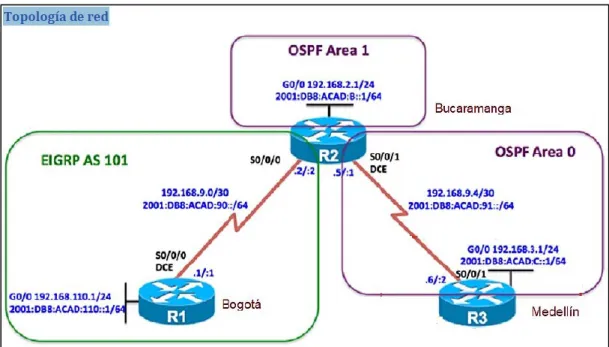
Una empresa de confecciones posee tres sucursales distribuidas en las ciudades de Bogotá, Medellín y Bucaramanga, en donde el estudiante será el administrador de la red, el cual deberá configurar e interconectar entre sí cada uno de los dispositivos que forman parte del escenario, acorde con los lineamientos establecidos para el direccionamiento IP, protocolos de enrutamiento y demás aspectos que forman parte de la topología de red.
Ilustración 1 Topología requerida escenario 1.
Configurar la topología de red, de acuerdo con las siguientes especificaciones.
1.1 Parte 1: Configuración del escenario propuesto
12
1. Configurar las interfaces con las direcciones IPv4 e IPv6 que se muestran en la topología de red.
Configuración direccionamiento R1 R1(config)#interface s0/0
R1(config-if)#ip address 192.168.9.1 255.255.255.252 R1(config-if)#no shut
R1(config-if)#ipv6 address 2001:DB8:ACAD:90::1/64 R1(config-if)#no shut
R1(config-if)#exit
R1(config)#interface s0/2
R1(config-if)#ip address 192.168.110.1 255.255.255.0 R1(config-if)#ipv6 address 2001:DB8:ACAD:110::2/64 R1(config-if)#no shut
Configuración direccionamiento R2. R2(config)#interface s0/0
R2(config-if)#ip address 192.168.9.2 255.255.255.252 R2(config-if)#ipv6 address 2001:DB8:ACAD:90::2/64 R2(config-if)#no shut
R2(config-if)#exit
R2(config)#interface s0/2
R2(config-if)#ip address 192.168.2.2 255.255.255.0 R2(config-if)#ipv6 address 2001:DB8:ACAD:8::2/64 R2(config-if)#no shut
R2(config)#interface s0/1
R2(config-if)#ip address 192.168.9.5 255.255.255.252 R2(config-if)#ipv6 address 2001:DB8:ACAD:91::1/64 R2(config-if)#no shut
Configuración direccionamiento R3. R3(config)#interface s0/1
R3(config-if)#ip address 192.168.9.6 255.255.255.252 R3(config-if)#ipv6 address 2001:DB8:ACAD:91::2/64 R3(config-if)#no shut
R3(config-if)#interface s0/2
R3(config-if)#ip address 192.168.3.2 255.255.255.0 R3(config-if)#ipv6 address 2001:DB8:ACAD:C::2/64 R3(config-if)#no shut
2. Ajustar el ancho de banda a 128 kbps sobre cada uno de los enlaces seriales ubicados en R1, R2, y R3 y ajustar la velocidad de reloj de las conexiones de DCE según sea apropiado
13 R1(config-if)#bandwidth 128
R1(config-if)#clock rate 64000
Ajuste ancho de banda y clockrate para R2. R2(config)#interface s0/0
R2(config-if)#bandwidth 128 R2(config-if)#exit
R2(config)#interface s0/1 R2(config-if)#bandwidth 128 R2(config-if)#clock rate 64000
Ajuste ancho de banda y clockrate para R3. R3(config)#int s0/0
R3(config-if)#bandwidth 128
3. En R2 y R3 configurar las familias de direcciones OSPFv3 para IPv4 e IPv6. Utilice el identificador de enrutamiento 2.2.2.2 en R2 y 3.3.3.3 en R3 para ambas familias de direcciones.
Configuración de OSPF V3 y Id de enrutamiento en R2. R2(config)#router ospf 3
R2(config-router)#router-id 2.2.2.2 R2(config-router)#exit
R2(config)#ipv6 unicast-routing R2(config)#ipv6 router ospf 3 R2(config-rtr)#router-id 2.2.2.2 R2(config-rtr)#
Configuración de OSPF V3 y Id de enrutamiento en R3. R3(config)#router ospf 3
R3(config-router)#router-id 3.3.3.3 R3(config-router)#exit
R3(config)#ipv6 unicast-routing R3(config)#ipv6 router ospf 3 R3(config-rtr)#router-id 3.3.3.3 R3(config-rtr)#
4. En R2, configurar la interfaz F0/0 en el área 1 de OSPF y la conexión serial entre R2 y R3 en OSPF área 0.
Configuración de área 0 Ospf en R2. R2(config)#int s0/2
R2(config-if)#ip ospf 3 area 1 R2(config-if)#ipv6 ospf 3 area 1 R2(config-if)#exit
R2(config)#int s0/1
14 R2(config-if)#ipv6 ospf 3 area 0
R2(config-if)#
5. En R3, configurar la interfaz F0/0 y la conexión serial entre R2 y R3 en OSPF área 0.
Configuración de área 0 Ospf en R3. R3(config)#int s0/1
R3(config-if)#ipv6 ospf 3 area 0 R3(config)#interface s0/2 R3(config-if)#ipv6 ospf 3 area 0 R3(config-if)#
6. Configurar el área 1 como un área totalmente Stubby.
Configuración de área 1 como stub. R2(config)#router ospf 3
R2(config-router)#area 1 stub no-summary R2(config-router)#exit
R2(config)#ipv6 router ospf 3
R2(config-rtr)#area 1 stub no-summary R2(config-rtr)#
7. Propagar rutas por defecto de IPv4 y IPv6 en R3 al interior del dominio OSPFv3. Nota: Es importante tener en cuenta que una ruta por defecto es diferente a la definición de rutas estáticas.
Propagación de rutas por defecto en R3. R3(config)#router ospf 3
R3(config-router)#network 192.168.3.0 0.0.0.255 area 0 R3(config-router)#network 192.168.9.4 0.0.0.3 area 0 R3(config-router)#
R3(config-rtr)#ipv6 route ::/0 2001:DBB:ACAD:C::1 R3(config-rtr)#ipv6 route ::/0 2001:DBB:ACAD:91::1 R3(config)#
8. Realizar la configuración del protocolo EIGRP para IPv4 como IPv6. Configurar la interfaz F0/0 de R1 y la conexión entre R1 y R2 para EIGRP con el sistema autónomo 101. Asegúrese de que el resumen automático está desactivado.
Configuración de EIGRP y sistema autónomo en R1. R1(config)#router eigrp 101
15 R1(config-router)#network 192.168.9.0 0.0.0.3 R1(config-router)#exit
R1(config)#ipv6 router eigrp 101 R1(config-rtr)#eigrp router-id 1.1.1.1
Configuración de EIGRP y sistema autónomo en R2. R2(config)#router eigrp 101
R2(config-router)#eigrp router-id 2.2.2.2
R2(config-router)#network 192.168.9.0 0.0.0.3 R2(config-router)#exit
R2(config)#ipv6 router eigrp 101 R2(config-rtr)#eigrp router-id 2.2.2.2 R2(config-rtr)#
9. Configurar las interfaces pasivas para EIGRP según sea apropiado.
Configuración de interfaces pasivas para EIGRP en R1. R1(config)#router eigrp 101
R1(config-router)#passive-interface s0/2 R1(config-router)#exit
R1(config)#ipv6 router eigrp 101 R1(config-rtr)#passive-interface s0/2 R1(config-rtr)#
Configuración de interfaces pasivas para EIGRP en R2. R2(config)#router eigrp 101
R2(config-router)#passive-interface s0/2 R2(config-router)#exit
R2(config)#ipv6 router eigrp 101 R2(config-rtr)#passive-interface s0/2 R2(config-rtr)#passive-interface s0/1
10. En R2, configurar la redistribución mutua entre OSPF y EIGRP para IPv4 e IPv6. Asignar métricas apropiadas cuando sea necesario.
Configuración de redistribución muta para OSPF y EIGRP en R3. R2(config)#router ospf 3
R2(config-router)#redistribute eigrp 101 subnets R2(config-router)#exit
R2(config)#ipv6 router ospf 3
R2(config-rtr)#redistribute eigrp 101 R2(config-rtr)#exit
R2(config)#router eigrp 101
R2(config-router)#redistribute ospf 3 R2(config-router)#exit
16 R2(config-rtr)#redistribute ospf 3
R2(config-rtr)#redistribute connected R2(config-rtr)#
11. En R2, de hacer publicidad de la ruta 192.168.3.0/24 a R1 mediante una lista de distribución y ACL.
Creación de ACL en R2 R2#conf ter
R2(config)#access-list 20 permit 192.168.3.0 0.0.0.255 R2(config)#int s0/1
R2(config-if)#ip access-group 20 in R2(config-if)#int s0/0
R2(config-if)#ip access-group 20 out R2(config-if)#
1.2 Parte 2: Verificar conectividad de red y control de la trayectoria.
a. Registrar las tablas de enrutamiento en cada uno de los routers, acorde con los parámetros de configuración establecidos en el escenario propuesto.
17
Ilustración 4 Ejecución comando Show ip route y Show ipv6 route en R2.
18
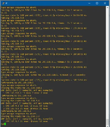
b. Verificar comunicación entre routers mediante el comando ping y traceroute.
Ilustración 6 Ejecución de ping y traceroute en R1
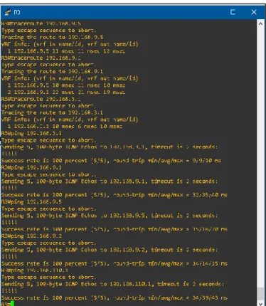
19
Ilustración 8 Ejecución de ping y traceroute en R3.
Nota: Puede ser que Una o más direcciones no serán accesibles desde todos los routers después de la configuración final debido a la utilización de listas de distribución para filtrar rutas y el uso de IPv4 e IPv6 en la misma red.
2. Escenario 2
20
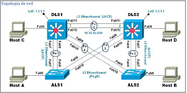
Ilustración 9 Topología requerida para el escenario 2.
2.1 Parte 1: Configurar la red de acuerdo con las especificaciones.
Ilustración 10 Ejecución de ping y traceroute en R3.
a. Apagar todas las interfaces en cada switch.
b. Asignar un nombre a cada switch acorde al escenario establecido.
Apagado de interfaces y asignación de nombre en ALS1. IOU3(config)#enable password cisco
IOU3(config)#enable secret class
IOU3(config)#ip domain-name CCNP.NET IOU3(config)#no ip domain lookup
IOU3(config)#interface range e0/0-3,e1/0-3,e2/0-3,e3/0-3 IOU3(config-if-range)#shutdown
21 IOU3(config)#line con 0
IOU3(config-line)#password cisco IOU3(config-line)#login IOU3(config-line)#no exec-timeout IOU3(config-line)#logging synchronous IOU3(config-line)#exit IOU3(config)#hostname ALS1 ALS1(config)#
Apagado de interfaces y asignación de nombre en DLS1. IOU1(config)#enable password cisco
IOU1(config)#enable secret class
IOU1(config)#ip domain-name CCNP.NET IOU1(config)#no ip domain lookup
IOU1(config)#interface range e0/0-3,e1/0-3,e2/0-3,e3/0-3 IOU1(config-if-range)#shutdown
IOU1(config-if-range)#exit IOU1(config)#line con 0
IOU1(config-line)#password cisco IOU1(config-line)#login IOU1(config-line)#no exec-timeout IOU1(config-line)#logging synchronous IOU1(config-line)#exit IOU1(config)#hostname DLS1 DLS1(config)#
Apagado de interfaces y asignación de nombre en DLS2. IOU2#conf ter
Enter configuration commands, one per line. End with CNTL/Z. IOU2(config)#enable password cisco
IOU2(config)#enable secret class
IOU2(config)#ip domain-name CCNP.NET IOU2(config)#no ip domain lookup
IOU2(config)#interface range e0/0-3,e1/0-3,e2/0-3,e3/0-3 IOU2(config-if-range)#shutdown
IOU2(config-if-range)#exit IOU2(config)#line con 0
IOU2(config-line)#password cisco IOU2(config-line)#login IOU2(config-line)#no exec-timeout IOU2(config-line)#logging synchronous IOU2(config-line)#exit IOU2(config)#hostname DLS2 DLS2(config)#
22 IOU4(config)#enable password cisco IOU4(config)#enable secret class
IOU4(config)#ip domain-name CCNP.NET IOU4(config)#no ip domain lookup
IOU4(config)#interface range e0/0-3,e1/0-3,e2/0-3,e3/0-3 IOU4(config-if-range)#shutdown
IOU4(config-if-range)#exit IOU4(config)#line con 0
IOU4(config-line)#password cisco IOU4(config-line)#login IOU4(config-line)#no exec-timeout IOU4(config-line)#logging synchronous IOU4(config-line)#exit IOU4(config)#hostname ALS2 ALS2(config)#
c. Configurar los puertos troncales y Port-channels tal como se muestra en el diagrama.
1) La conexión entre DLS1 y DLS2 será un EtherChannel capa-3 utilizando LACP. Para DLS1 se utilizará la dirección IP 10.12.12.1/30 y para DLS2 utilizará 10.12.12.2/30.
Configuración de Etherchanel para DLS1. DLS1#conf ter
DLS1(config)#interface e1/1
DLS1(config-if)#channel-group 1 mode active DLS1(config-if)#no shut
DLS1(config-if)#exit DLS1(config)#
DLS1(config)#int e1/0
DLS1(config-if)#channel-group 1 mode active DLS1(config-if)#no shut
DLS1(config-if)#exit DLS1(config)#
DLS1(config)#interface port-channel 1 DLS1(config-if)#no switchport
DLS1(config-if)#
DLS1(config-if)#ip address 10.12.12.1 255.255.255.252 DLS1(config-if)#no shut
Configuración de Etherchanel para DLS2. DLS2#conf ter
DLS2(config)#int e1/1
23 DLS2(config-if)#
DLS2(config-if)#exit DLS2(config)#int e1/0
DLS2(config-if)#channel-group 1 mode active DLS2(config-if)#no shut
DLS2(config-if)#exit
DLS2(config)#int port-channel 1 DLS2(config-if)#no switchport
DLS2(config-if)#ip address 10.12.12.2 255.255.255.252 DLS2(config-if)#no shut
DLS2(config-if)#exit DLS2(config)#
2) Los Port-channels en las interfaces Fa0/7 y Fa0/8 utilizarán LACP.
Configuración de LACP para DLS1. DLS1(config)#int e0/0
DLS1(config-if)#channel-group 2 mode active DLS1(config-if)#no shut
DLS1(config-if)#exit DLS1(config)#int e0/1
DLS1(config-if)#channel-group 2 mode active DLS1(config-if)#no shut
DLS1(config-if)#exit DLS1(config)#
Configuración de LACP para DLS2. DLS2(config)#int e0/0
DLS2(config-if)#channel-group 2 mode active DLS2(config-if)#no shut
DLS2(config-if)#exit DLS2(config)#int e0/1
DLS2(config-if)#channel-group 2 mode active DLS2(config-if)#no shut
DLS2(config-if)#exit DLS2(config)#
Configuración de LACP para ALS1. ALS1(config)#int e0/0
ALS1(config-if)#channel-group 2 mode active ALS1(config-if)#no shut
ALS1(config-if)#exit ALS1(config)#int e0/1
24 ALS1(config-if)#exit
ALS1(config)#
Configuración de LACP para ALS2. ALS2(config)#int e0/0
ALS2(config-if)#channel-group 2 mode active ALS2(config-if)#no shut
ALS2(config-if)#exit ALS2(config)#int e0/1
ALS2(config-if)#channel-group 2 mode active ALS2(config-if)#no shut
ALS2(config-if)#exit ALS2(config)#
3) Los Port-channels en las interfaces F0/9 y fa0/10 utilizará PAgP.
Configuración de PAgP para DLS1. DLS1(config)#int e0/3
DLS1(config-if)#channel-group 3 mode desirable DLS1(config-if)#no shut
DLS1(config-if)#exit DLS1(config)#int e0/2
DLS1(config-if)#channel-group 3 mode desirable DLS1(config-if)#no shut
DLS1(config-if)#exit DLS1(config)#
Configuración de PAgP para DLS2. DLS2(config)#int e0/3
DLS2(config-if)#channel-group 3 mode desirable DLS2(config-if)#no shut
DLS2(config-if)#exit DLS2(config)#int e0/2
DLS2(config-if)#channel-group 3 mode desirable DLS2(config-if)#no shut
DLS2(config-if)#exit DLS2(config)#
Configuración de PAgP para ALS1. ALS1(config)#int e0/3
ALS1(config-if)#channel-group 3 mode desirable ALS1(config-if)#no shut
ALS1(config-if)#exit ALS1(config)#int e0/2
25 ALS1(config-if)#no shut
ALS1(config-if)#exit ALS1(config)#
Configuración de PAgP para ALS2. ALS2(config)#int e0/3
ALS2(config-if)#channel-group 3 mode desirable ALS2(config-if)#no shut
ALS2(config-if)#exit ALS2(config)#int e0/2
ALS2(config-if)#channel-group 3 mode desirable ALS2(config-if)#no shut
ALS2(config-if)#exit ALS2(config-if)#
4) Todos los puertos troncales serán asignados a la VLAN 800 como la VLAN nativa.
Configuración de Vlan nativa 800 en DLS1. DLS1(config)#vlan 800
DLS1(config-vlan)#name NATIVA DLS1(config-vlan)#exit
DLS1(config)#interface range e0/0-3,e1/0-1
DLS1(config-if-range)#switchport trunk native vlan 800 DLS1(config-if-range)#exit
Configuración de Vlan nativa 800 en DLS2. DLS2(config)#vlan 800
DLS2(config-vlan)#name NATIVA DLS2(config-vlan)#exit
DLS2(config)#interface range e0/0-3,e1/0-1
DLS2(config-if-range)#switchport trunk native vlan 800 DLS2(config-if-range)#exit
Configuración de Vlan nativa 800 en ALS1. ALS1(config)#vlan 800
ALS1(config-vlan)#name NATIVA ALS1(config-vlan)#exit
ALS1(config)#interface range e0/0-3,e1/0-1
ALS1(config-if-range)#switchport trunk native vlan 800 ALS1(config-if-range)#exit
Configuración de Vlan nativa 800 en ALS2. ALS2(config)#vlan 800
ALS2(config-vlan)#name NATIVA ALS2(config-vlan)#exit
26
ALS2(config-if-range)#switchport trunk native vlan 800 ALS2(config-if-range)#exit
d. Configurar DLS1, ALS1, y ALS2 para utilizar VTP versión 3 1) Utilizar el nombre de dominio UNAD con la contraseña cisco123
1) Configurar DLS1 como servidor principal para las VLAN.
DLS1(config)#vtp domain UNAD DLS1(config)#vtp password cisco123 DLS1(config)#vtp versión 3
DLS1(config)#vtp mode server DLS1(config)#
2) Configurar ALS1 y ALS2 como clientes VTP.
ALS1(config)#vtp domain UNAD ALS1(config)#vtp password cisco123 ALS1(config)#vtp version 3
ALS1(config)#vtp mode client ALS1(config)#
ALS2(config)#vtp domain UNAD ALS2(config)#vtp password cisco123 ALS2(config)#vtp version 3
ALS2(config)#vtp mode client ALS2(config)#
e. Configurar en el servidor principal las siguientes VLAN:
Número de VLAN Nombre de VLAN Número de VLAN Nombre de VLAN
800 NATIVA 434 ESTACIONAMIENTO
12 EJECUTIVOS 123 MANTENIMIENTO
234 HUESPEDES 1010 VOZ
1111 VIDEONET 3456 ADMINISTRACIÓN
Tabla 1. Vlans
27 DLS1(config)#vlan 434 DLS1(config-vlan)#name ESTACIONAMIENTO DLS1(config-vlan)#exit DLS1(config)#vlan 123 DLS1(config-vlan)#name MANTENIMIENTO DLS1(config-vlan)#exit DLS1(config)#vlan 1010 DLS1(config-vlan)#name VOZ DLS1(config-vlan)#exit DLS1(config)#vlan 3456 DLS1(config-vlan)#name ADMINISTRACION DLS1(config-vlan)#exit DLS1(config)#
f. En DLS1, suspender la VLAN 434.
DLS1#conf ter
DLS1(config)#vlan 434
DLS1(config-vlan)#state suspend DLS1(config-vlan)#exit
DLS1(config)#
g. Configurar DLS2 en modo VTP transparente VTP utilizando VTP versión 2, y configurar en DLS2 las mismas VLAN que en DLS1.
DLS2(config)#vtp version 2
28 DLS2(config-vlan)#name ADMINISTRACION DLS2(config-vlan)#exit
DLS2(config)#
h. Suspender VLAN 434 en DLS2.
DLS2(config)#vlan 434
DLS2(config-vlan)#state suspend DLS2(config-vlan)#exit
DLS2(config)#
i. En DLS2, crear VLAN 567 con el nombre de CONTABILIDAD. La VLAN de CONTABILIDAD no podrá estar disponible en cualquier otro Switch de la red.
DLS2(config)#vlan 567
DLS2(config-vlan)#name CONTABILIDAD DLS2(config-vlan)#exit
DLS2(config)#
j. Configurar DLS1 como Spanning tree root para las VLAN 1, 12, 434, 800, 1010, 1111 y 3456 y como raíz secundaria para las VLAN 123 y 234.
DLS1(config)#spanning-tree vlan 1 root primary DLS1(config)#spanning-tree vlan 12 root primary DLS1(config)#spanning-tree vlan 434 root primary DLS1(config)#spanning-tree vlan 800 root primary DLS1(config)#spanning-tree vlan 1010 root primary DLS1(config)#spanning-tree vlan 1111 root primary DLS1(config)#spanning-tree vlan 3456 root primary DLS1(config)#spanning-tree vlan 123 root secondary DLS1(config)#spanning-tree vlan 234 root secondary DLS1(config)#
k. Configurar DLS2 como Spanning tree root para las VLAN 123 y 234 y como una raíz secundaria para las VLAN 12, 434, 800, 1010, 1111 y 3456.
29
l. Configurar todos los puertos como troncales de tal forma que solamente las VLAN que se han creado se les permitirá circular a través de éstos puertos.
Configuración de puertos en modo troncal para DLS1. DLS1(config)#interface range e0/0-3,e1/0-3,e2/0-3,e3/0-3 DLS1(config-if-range)#switchport trunk encapsulation dot1q DLS1(config-if-range)#switchport mode trunk
DLS1(config-if-range)#
Configuración de puertos en modo troncal para DLS2. DLS2(config)#interface range e0/0-3,e1/0-3,e2/0-3,e3/0-3 DLS2(config-if-range)#switchport trunk encapsulation dot1q DLS2(config-if-range)#switchport mode trunk
DLS2(config-if-range)#exit
Configuración de puertos en modo troncal para ALS1. ALS1(config)#interface range e0/0-3,e1/0-3,e2/0-3,e3/0-3 ALS1(config-if-range)#switchport trunk encapsulation dot1q ALS1(config-if-range)#switchport mode trunk
ALS1(config-if-range)#exit ALS1(config)#
Configuración de puertos en modo troncal para ALS2. ALS2(config)#interface range e0/0-3,e1/0-3,e2/0-3,e3/0-3 ALS2(config-if-range)#switchport trunk encapsulation dot1q ALS2(config-if-range)#switchport mode trunk
ALS2(config-if-range)#exit ALS2(config)#
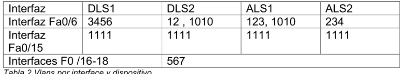
m. Configurar las siguientes interfaces como puertos de acceso, asignados a las VLAN de la siguiente manera:
Tabla 2 Vlans por interface y dispositivo.
Configuración de Vlan en puertos indicados para DLS1. DLS1(config)#int e1/2
DLS1(config-if)#switchport mode access
Interfaz DLS1 DLS2 ALS1 ALS2
Interfaz Fa0/6 3456 12 , 1010 123, 1010 234
Interfaz Fa0/15
1111 1111 1111 1111
30 DLS1(config-if)#switchport access vlan 3456 DLS1(config-if)#no shut
DLS1(config-if)#exit DLS1(config)#int e1/3
DLS1(config-if)#switchport mode access DLS1(config-if)#switchport access vlan 1111 DLS1(config-if)#no shut
DLS1(config-if)#exit DLS1(config)#
Configuración de Vlan en puertos indicados para DLS2. DLS2(config)#int e1/2
DLS2(config-if)#switchport mode access DLS2(config-if)#switchport access vlan 123 DLS2(config-if)#no shut
DLS2(config-if)#exit
DLS2(config)#int range e2/0-3, e3/0-3
DLS2(config-if-range)#switchport mode access DLS2(config-if-range)#switchport access vlan 567 DLS2(config-if-range)#no shut
DLS2(config-if-range)#exit DLS1(config)#int e1/3
DLS1(config-if)#switchport mode access DLS1(config-if)#switchport access vlan 1111 DLS1(config-if)#no shut
DLS2(config)#
Configuración de Vlan en puertos indicados para ALS1. ALS1(config)#int e1/2
ALS1(config-if)#switchport mode access ALS1(config-if)#no switchport access vlan 123 ALS1(config-if)#no shut
ALS1(config-if)#exit ALS1(config)#int e1/3
ALS1(config-if)#switchport mode access
ALS1(config-if)#no switchport access vlan 1111 ALS1(config-if)#no shut
ALS1(config-if)#exit ALS1(config)#
Configuración de Vlan en puertos indicados para ALS2. ALS2(config)#int e1/2
31 ALS2(config-if)#exit
ALS2(config)#int e1/3
ALS2(config-if)#switchport mode access ALS2(config-if)#switchport access vlan 1111 ALS2(config-if)#no shut
ALS2(config-if)#exit
2.2 Part 2: conectividad de red de prueba y las opciones configuradas.
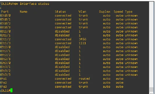
a. Verificar la existencia de las VLAN correctas en todos los switches y la asignación de puertos troncales y de acceso
Ilustración 11 Ejecución comando Show interface status en DLS1.
32
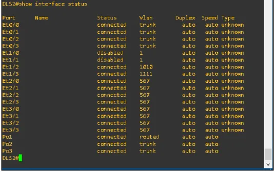
Ilustración 13 Ejecución comando Show interface status en DLS2.
33
Ilustración 15 Ejecución comando Show interface status en ALS1.
34
Ilustración 17 Ejecución comando Show interface status en ALS2.
Ilustración 18 Ejecución comando Show vlan brief en ALS2.
35
Ilustración 19 Ejecución comando Show etherchannel summary en DLS1
36
c. Verificar la configuración de Spanning tree entre DLS1 o DLS2 para cada VLAN.
Ilustración 21 Ejecución comando Show spanning-tree summary en DLS1.
37
CONCLUSIONES.
- El conocimiento y manejo de los diferentes protocolos de enrutamiento y
conexión, así como también de las funcionalidades de cada uno de los dispositivos de red, permiten generar soluciones más eficientes a problemas de comunicación o implementaciones de red que deben cumplir con ciertos requerimientos.
- El manejo adecuado de los protocolos de comunicación y enrutamiento
de redes, así como también de las funcionalidades de seguridad que nos proporcionan los dispositivos de red, garantizan la confiabilidad de las redes de comunicaciones y minimizan los riesgos de seguridad que se pueden presentar dentro de esta, evitando filtrado o perdida de información para la entidad en la cual lo estamos implementando.
- La implementación de una red de comunicación extensa que involucre
38
BIBLIOGRAFÍA.
- Docplayer. Comandos Cisco Switch. {En línea}. {2019/12/13}. Disponible
en https://docplayer.es/5049672-Comandos-cisco-switch.html
- Cisco. Guía de diseño de OSPF. {En línea}. {2019/12/14}. Disponible en
https://www.cisco.com/c/en/us/support/docs/ip/open-shortest-path-first-ospf/7039-1.html
- Cisco. Introducción a EIGRP. {En línea}.{2019/12/15}. Disponible en
https://www.cisco.com/c/en/us/support/docs/ip/enhanced-interior-gateway-routing-protocol-eigrp/13669-1.html
- Teare, D., Vachon B., Graziani, R. {2015}. CISCO Press (Ed). OSPF
Implementation. Implementing Cisco IP Routing (ROUTE) Foundation Learning Guide CCNP ROUTE 300-101. Disponible en https://1drv.ms/b/s!AmIJYei-NT1IlnMfy2rhPZHwEoWx
- UNAD {2015}. Introducción a la configuración de Switches y Routers
{OVA}. Disponible en https://1drv.ms/u/s!AmIJYei-NT1IhgL9QChD1m9EuGqC
- Froom, R., Frahim, E. {2015}. CISCO Press (Ed). Spanning Tree