Wearable Soft Robotic Device for Post-Stroke Shoulder
Rehabilitation: Identifying Misalignments
Ignacio Galiana. Frank L. Hammond III Robert D. Howe, and Marko B. Popovic
Abstract—Stroke is the leading cause of long-term disability in the United States, affecting over 795,000 people annually. In order to regain motor function of the upper body, patients are usually treated by regular sessions with a dedicated physical therapist. A cost-effective wearable upper body orthotics system that can be used at home to empower both the patients and physical therapists is described. The system is composed of a thin, compliant, lightweight, cost-effective soft orthotic device with an integrated cable actuation system that is worn over the upper body, an embedded limb position sensing system, an electric actuator package and controller. The proposed device is robust to misalignments that may occur during actuation of the compliant brace or when putting on the system. Through simulations and experimental evaluation, it was demonstrated i) that the soft orthotic cable-driven shoulder brace can be successfully actuated without the production of off-axis torques in the presence of misalignments and ii) that the proposed model can identify linear and angular misalignments online.
i. INTRODUCTION
Strokes affect over 795,000 people annually in the United States and 15 million worldwide [1]. This significant and disabling condition can result in paralysis of upper and/or lower limbs that must be treated by regular sessions with a dedicated physical therapist in order to regain motor function [2], [3]. However, the use of therapists is expensive, in high demand, and requires frequent visits to a rehabilitation clinic. We propose a cost-effective and wearable active upper body soft orthotic system that can be used at home or at a clinic to empower patients and therapists by providing assistive forces and diagnostic sensing that can help deliver the same level of rehabilitation as the current physical therapy standard of care. The system will use inexpensive sensing and actuation components to create an economical rehabilitation system accessible to and affordable by patients worldwide.
Previous solutions for actuated upper body rehabilitation devices have used robotic exoskeletons [4-8]. These exoskeletons contain rigid links and joints that limit kinematic degrees of freedom (DoF) to constrain the motion
*Research partially supported by SPS award by the American Institute of Physics (M.B.P), "Personal Investigador en Formación" from Universidad Politécnica de Madrid (UPM) (I.G.) and support from Maxon Motors.
Ignacio Galiana is with Centre for Automation and Robotics UPM-CSIC, Madrid, 28006 Spain, e-mail: ignacio.galiana@upm.es
Frank L. Hammond III and Robert D. Howe are with the Harvard School of Engineering and Applied Sciences, Cambridge, MA, 02138 USA. e-mail: fhammond@seas.harvard.edu; howe@seas.harvard.edu.
Ignacio Galiana is also with the Harvard School of Engineering and Applied Sciences, Cambridge, MA, 02138 USA.
Robert D. Howe is also with the Harvard-MIT Division of Health Sciences & Technology, Cambridge, MA, 02139 USA.
Marko B. Popovic is with Worcester Polytechnic Institute, Worcester, MA, USA, email: mpopovic@wpi.edu
of the wearer and promote safe joint articulations. However, due to substantial skin-bone relative motion which occurs at patient-device interface, exoskeletons can also cause unsafe misalignments between the biological and artificial rigid joints if the device is improperly applied to a patient. This
means that precautions must be taken during device design to ensure adaptability to anatomical variations in patients and to prevent patient injury. For example, Agrawal et al. created a rigid system of six shoulder-mounted motors and cables to actuate the arm in multiple DOF [9],[10],[11]. While this system's kinematics were optimized to achieve a useful range of motion, precise adjustments of the rigid parts are required to avoid misalignments that may occur when putting on and taking off the system or during the exercise.
In addition to human factors issues, rigid exoskeletons, due to their mechanical complexity, can be economically prohibitive and limited in functionality. Ueda et al. attached pneumatic muscles to a rigid, wearable device to anthropomorphically apply actuation forces to the human arm [12]. Though this solution is adequate for in-clinic use, conventional pneumatics is a too expensive and complicated actuation method to be used in an at-home device. Moreover, pneumatic systems cannot support a fully mobile wearable assistive system due to a relatively small energy density associated with the required compressed air tank.
Previous work on a soft orthotic shoulder rehabilitation device provided a manually actuated initial prototype of the Soft Robotics Brace and provided a proof of concept that this type of brace can be successfully actuated with biologically-realistic forces [13]. Furthermore, it was demonstrated that arm angular position can be accurately estimated with embedded inexpensive, piezoresistive flex sensors [14] or Inertial Measurement Units (IMUs) [15].
Section II describes the soft orthotic system concept and requirements. Section III describes the kinematic design of the cable-driven system to compensate for linear and angular misalignments and the system prototype design and control. Section IV describes simulation and experimental results of the proposed methods and Section V summarizes conclusions.
II. SYSTEM CONCEPT AND REQUIREMENTS
The design of the proposed soft orthotic device for shoulder rehabilitation is based upon the following requirements:
1. It should be compliant to improve safety. Rigid elements are avoided.
2. It must be adaptable to anatomical variations and misalignments.
3. Easy to don and doff. 4. It must be as light as possible.
5. It should generate forces to assist during the rehabilitation process and measure the arm posture. 6. It should be a cost-effective system.
The first requirement is related to designing a device that is compliant; this will improve safety for the rehabilitation procedure and any other application.
The second requirement refers to making the system easily adaptable to patients' anatomical variations so that the same system can be used by most patients. Also, as the device will be compliant, it has to be considered in the control that misalignments will appear due to anatomical variations, misplacement of the system and due to the actuation during the exercise.
The third and fourth requirements refer to designing a device comfortable to use for post-stroke patients. The device should be easy to use so that stroke patients themselves or a family member can put on and take off the system to perform rehabilitation exercises at home.
The fifth requirement is related to the appropriate selection of the actuation and sensing devices to provide the
Figure 1. Soft-Orthotic System Concept
required forces during rehabilitation and to measure the arm position for control implementation and to monitor the patient's progress to assist in objective diagnosis. This information will allow health practitioners to better adjust the exercises to the patient's specific disability.
The sixth requirement aims to design a system that can be affordable to patients and/or health institutions.
The conceptual design of a soft-orthotic device for upper-limb rehabilitation is shown in Fig. 1.
III. METHODS
Considering concept and requirements described in previous section, a cable driven system that can provide full actuation of patient's arm in the abduction/adduction DOF was designed.
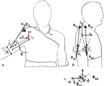
The designed device is cable-driven and provides torques to move the arm in the abduction/adduction degree of freedom (DoF). It was previously demonstrated that if only one cable is considered, off-axis torques will appear when there is angular misalignment of the cables' attachment points [13]. Hence, the proposed model consists of two cables that attach to the upper arm brace (one on each side) passing over two rigid "towers" on the shoulder that distribute force over the user's tissue to minimize force concentrations and to raise and extend the cable to enhance lifting ability as shown in Fig. 2.
In this section, the kinematic model of the human arm and the cable system are designed to determine proper tower positions and cable attachment points that allow identifying and adapting to linear and angular misalignments of the brace. Moreover, a prototype of the system that is used in following sections to validate the identification process is described.
A. Kinematic Design for Misalignment Compensation The designed device is cable-driven and provides torques to move the arm in the abduction/adduction degree of freedom (DOF) identifying and adapting to misalignments.
PAI
Kinematics considered to model cable driven system is shown in Fig. 2. In this model a fixed world frame at the true center of rotation of the shoulder joint (modeled as a ball joint) is assumed. Actuation cables pass over a rigid tower and attach to each side of the compliant brace.
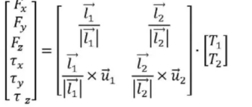
The Jacobian function that relates cable tensions' with the forces and torques produced at the center of rotation of the arm joint was calculated (Eq.l) [16]. To determine the cable tensions that are needed to produce a torque in the abduction/adduction DoF a linear least squares non-negativity constraints solution Matlab's Isqnonneg function was used to solve equation (1).
If any misalignment occurs, either when putting on the system or during the rehabilitation process when actuating the brace, the position of the attachment points of the compliant brace will change. This deviation is defined by parameters r (distance to the shoulder joint) and a (angular misalignment) as shown in Fig. 2, and strongly affects the Jacobian matrix (Eq. 1) causing different torques than those desired. In order to cope with these misalignments it is necessary to run an online identification of the system parameters to calculate the actual values for r and a.
F* =
Ty T ,
-u
u
k
-.
k
-.
=T7 X U1 — r - X U2
k
(1)
Where lt is the vector from each cable attachment point
in the brace to each cable tower (lL = PAl - PTl ), TtL is the
vector from each cable attachment point to the arm center of rotation TtL = (PAl - CL) and F, T are force and torque
transmitted to the joint respectively.
In this system, gravitational compensation of the arm weight for any position of the arm in the workspace was considered. Rehabilitation exercises for post-stroke patients are usually performed at low speed; hence, dynamics have been neglected. By analyzing the Jacobian matrix and taking into account misalignment parameters, position of the towers (Pn) was decided so the system can compensate for any linear or angular misalignment of the brace avoiding the production of off-axis torques. The condition that the Jacobian matrix has to satisfy so that only torques in the correct direction are produced for the abduction/adduction case is the following:
0
k
-.
7=^7 X Mi T± +
k
.,
i = ^X U2
0
~T9
L o J =
J J
J 41
hi Ueil
4 2
4 1 Ti +
7 6 2
''hi J 42
J 52
•J62
(2)
(3)
(4)
Tower positions were chosen so that equation (4) is satisfied for every value of linear or angular misalignment in any position of the brace. In this case, a single tower for both
cables located in the centerline of the shoulder was selected as it satisfies equation (4) (Ptlx=Pt2x; Ptly=Pt2y=0; Ptlz=Pt2z).
It is known that cable driven systems require redundancy in the application of forces due to the fact that cables can only pull. By measuring lengths of the cables and the position of the arm, equations to calculate the misalignment parameters online can be found. Geometrical equations were calculated (Eq.5) following the model in Fig. 2.
\ll\=f(e,PT1,PT2,h,r,a) (5)
For the proposed system PTI=PT2. By measuring cable lengths and arm posture and assuming position of the tower and width (h) of arm are known, r and a parameters that best fit the model can be calculated. The brace is a compliant fabric and hence parameters r and a will vary when actuating due to deformations or due to initial misplacement of the system. Estimating these values online will allow exerting the correct torque to the shoulder with compliant fabrics even if the brace is not perfectly positioned. As it will be described later in this section position of the arm will be measured by DVIUs or electro-magnetic (EM) Trackers and cable lengths are measured by encoders of the motors. Parameter h can be easily measured for each patient and the positions of the tower are supposed to be at a fixed location on the shoulder, therefore parameters r and a were chosen as the most important identification parameters. Arm mass is also patient specific and in a future version will be set by the therapist or estimated by reading the actuators' current to hold the patient arm at a specific position.
B. Two-Cable Compliant Brace System Prototype
A prototype of the Soft Orthotic system that fulfills requirements described in previous section and that has 2 cables in order to compensate for angular and linear misalignments was designed.
This prototype consists of a compliant, thin, light-weight fabric garment without rigid elements that monitors patient's posture and has two cable-driven series elastic actuators to provide assistive forces in the abduction/adduction DoF. Moreover, equations described before were implemented in
Actuation Cables
the controller to identify misalignments of cable's attachment points.
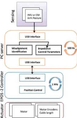
In this section we will describe the different components of the system as shown in Fig. 4:
1) Sensors to monitor patient's posture:
Sensors are a core part of this system as they will be used both for controlling the soft-orthotic device and to monitor patient's progress during the exercise. This information can be used by the therapist to adapt exercises to the patient's specific disability/range of movement, assess improvement and to encourage the patient to continue the exercises.
An analysis of different sensor systems was made in order to select a cost-effective precise solution to measure patient's arm posture. Electro Magnetic tracker Flock of Birds system by Ascension was used for preliminary tests and to test accuracy of other more portable and cost effective methods. Two ways of measuring arm posture were tested: Inertial Measurement Units (IMUs) and piezoresistive flex sensors by Spectra Symbol. By comparing this system with the Flock of Birds system it was demonstrated that arm angular position can be accurately measured with embedded inexpensive, piezoelectric flex sensors. The mean difference in between abduction angle reading by inexpensive $12 flex sensor in foam casing and reading by highly accurate $8500 Flock of Birds EM tracker was 5.8 degrees. The RMS between abduction angle by inexpensive $50 Inertial Measurement Unit (IMU) and by EM tracker was 3.6 degrees [15]. Due to their acceptable cost, precision, reduced size and weight IMUs will be used for the final system.
2) Cable Driven Electric Actuators:
Cable driven electric actuators in series with elastic elements (compliant brace and system) were used to actuate this prototype. Series-elastic-actuations provide a robust solution as it protects the actuators from shocks [17] and more importantly protect human from application of potentially large forces. Electric actuators from Maxon Motors EC-max 22 series with a digital Magneto-resistant (MR) encoder (with an accuracy of 512 counts per turn) were chosen to actuate the system due to their torque capability and reduced size and weight. Moreover, electric actuation
Tension in Cable 1
'in
c
5J
IMU or EM:
Arm Posture
r
a)
Q-Mlsallgnment Identification
1-Impedance Controf Parameters
100 Ml
USB Interface
Position Control
Q
v_
Motar Encoders: Cable length
Figure 4. Sensing and Control. Misalignment identification can be used to change control parameters of the system.
will include an electric battery. It has been shown that the energy density, i.e. mass per stored energy, of a lithium battery is larger than that of compressed air system. The system comprised of an electric battery and motor is substantially lighter and smaller than a pneumatic system with same specifications and hence more appropriate for fully mobile, wearable assistive system.
A mechanical coupler was positioned at the end of the actuator in order to make the system robust and assure that the motor does not receive any off axis force or torque that would deteriorate it. A spool was used in order to transform the output rotation of the motor in a linear motion of the cable achieving a maximum tension at each cable of 100 N which is more than enough to move a patient's arm [13]. Flexible Bowden cables were used to improve comfort of the user and portability of the system. Total weight of the
Tension in Cable 1
- 1 0 1 2
Linear m i s a l i g n m e n t [cm]
- S O S
Angular missalignment [°]
wearable brace is less than 300 g (actuation package weight is not included as is not worn by the patient)
3) Control system
EPOS-2 24/2 digital positioning controller from Maxon Motors was used to control the position of the device. This controller includes the motor amplifier, reads the motor encoder values and support different modes of operation of the motor such as current control, position control and velocity control of the device. Fig. 4. shows a general description of the control architecture that was implemented. The misalignment identification process described previously was implemented to detect the actual position of the brace when actuated.
The cost of this first prototype is as follows: each actuator package (motor, gear and encoder) is $406.57; each controller is 392.83 $, the fabric garment is 156.56$, IMU sensors are 50$ each; cables, Bowden cables and cables are 50$ in total. The total price for this first prototype (including 2 actuators, 2 controllers, 2 DVIUs and cables) is 1886$ which can be reduced for the final system if several devices are produced.
IV. RESULTS
In this section results for the simulation model, experimental identification of misalignment parameters when actuating the brace prototype by using model described in Section III.B are described.
A. Simulation Results: Gravitational Compensation. The model described in section II.A was tested in order to calculate the needed tensions in both cables to produce the required gravitational torque with zero off-axis torque when misalignments occur. Two conditions were tested:
(1) Linear misalignment: linear misalignment varying from -5 to 6 cm to hold the arm in different angles (theta) without angular misalignment was simulated. Tension in both cables must be the same in order to hold the arm without the production of off-axis torques. Fig. 5.a. shows tensions required in cable 1 with varying linear misalignment when angular misalignment equals 0.
(2) Angular misalignment: An angular misalignment varying from -20° to 20° was simulated. The required tensions in both cables for the proposed system satisfy the following equation: Tl(a)= T2(-a). Fig. 5.b. shows the required tensions in cable 1 (Tl) in order to hold the arm still without off-axis torques.
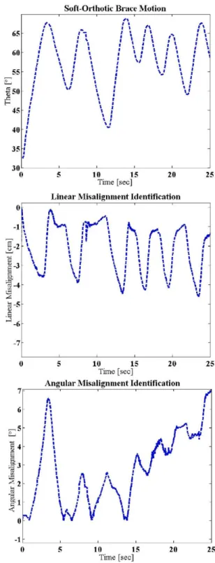
B. Experimental Results: Compliant Brace Misalignment Identification while Moving.
Equations shown in Section III. A were implemented to identify misalignments during operation of the brace. In this experiment the brace shown in Fig. 3.a. was position-controlled with initial gains in order to follow a trajectory in the abduction/adduction degree of freedom. Lengths of the cables were measured by using the encoder values of the actuators and position of the arm was measured by using an EM tracker (Flock of Birds system). The two cable-driven system prototype brace was moved performing an oscillatory motion. The identification routine and the model described in section III was programmed in order to: i) provide the initial
value of the r and alpha parameters (i.e. the initial position of the jacket when the user puts it on) and ii) identify misalignments on-line while moving the arm. The system is compliant in order to guarantee a safe operation for patients; this compliance causes the system to deform when actuated.
Soft-Orthotic Brace M o t i o n
f\
65
60
55
I 50
H
45
40
35
30
• 1
t 1
1 I I \
J l '
i t '
/ I
f 1 1 t 1 • 1
• '. •
• i i > •
i J • i
i i
\ 1
1 1
\ Í •
1 1 \
v \ !
t 1
\J
r
¡ 1 1
1 l '
• 1 I 1 1
1 1 1 I
I 1
• J
V \
i
-10 15
Time [sec]
20 25
Linear Misalignment Identification
0
-1
^ - 2
I
¡3-5-.3
J- 6
u
! \ I ¡ i * í \ •
< \
i \\ \\ \
i-\ • I I J i-\ I
V
10 15 Time [seo]
20 25
A n g u l a r Misalignment Identification
71
A
AJ
n
¡r*
W
V
l\
y
10 15 Time [sec]
20 25
Fig. 6.a. shows the motion performed by the system prototype; Fig. 6.b. and c. show the identification of linear and angular misalignments respectively. Initial values for r and alpha were measured before moving the system in order to check that the identification routine was properly defined, obtained parameters coincided with those measured. It can be seen that when moving the arm up linear misalignment increases returning to a value similar to the initial when not actuated.
On-line identification results were as expected. This identification process will allow easier don and doff of the system: with this architecture patients will not need to be accurate when putting on the system as any misalignment will be identified; moreover, deformations caused by the compliance and flexibility of the brace are identified on-line in order to update the model and provide the correct assistive torques.
V. CONCLUSION AND DISCUSSION
In this paper, a cable-driven compliant soft-orthotic device that can be worn over the upper body to generate effective torques to move the arm through a set of assistive motions is described. Most of the state-of-the-art systems rely on rigid elements that are not easily adaptable to patient's anatomical variations in order to avoid any misalignment during actuation. The fact that the device is elastic protects patients from application of potentially large forces. While other devices are based on pneumatic actuation the designed prototype uses electric motors transmitted with Bowden cables to the compliant brace (series elastic actuation). This approach is better suited for full mobility as energy density of electric batteries is higher than that of compressed air. Sensors used to develop upper limb rehabilitation devices were tested and it was demonstrated that IMUs can provide cost-effective measurements (3.6° measurement error with respect to other expensive solutions such as Electro Magnetic trackers).
A methodology to identify misalignments online when putting on the brace and when performing the exercise was implemented. This method relies on cable lengths and arm position measurement to identify the actual linear and angular misalignment values. Simulations demonstrated that a solution with 2 actuation cables can compensate brace misalignments in the Abduction/Adduction DOF avoiding off-axis torques. Experimental results on a prototype brace show that the identification routine provides consistent online estimation of the brace angular and linear deformation while performing the rehabilitation exercise. This method allows a compliant, easier to use system in which the patient doesn't need accuracy when wearing the device.
Future works will focus on developing an actuated soft-orthotic brace that can adapt to positioning misalignments while providing actuation torques for the shoulder 3 DOFs (abduction / adduction, internal / external rotation and flexion / extension). The designed system can be used both as a measuring tool and as an active device, two applications will be explored with patients: i) a doctor wears the brace (without actuation) performs the rehabilitation motion save this recording and uploads the rehabilitation exercise to the patient's brace and ii) doctor teleoperates the patient's brace.
ACKNOWLEDGMENT
The authors would like to thank Randie M. Black-Schaffer, MD, MA, Medical Director of Stroke Program at Spaulding Rehabilitation Hospital and her colleagues for the clinical insight they provided on the topic of post-stroke rehabilitation. Authors would also like to thank Neil Tenenholtz at Harvard School of Engineering and Applied Sciences for his insights in the identification process.
REFERENCES
[I] Stroke Center, http://www.strokecenter.org/patients/about-stroke/stroke-statistics/ (February 2012)
[2] B. Kibler, "Shoulder rehabilitation: principles and practice", Clinical Supplement: The Shoulder, vol 30, 1998, pp. 40-50.
[3] R. Donatelli, "Physical Therapy of the Shoulder" Clinics in Physical Therapy, 2003.
[4] H. I. Krebs, N. Hogan, et al., "Overview of clinical trials with MIT-MANUS: a robot-aided neuro-rehabilitation facility", Technology Health Care. vol. 7, pp. 419-23, 1999.
[5] L E. Kahn, et al., "Robot-assisted reaching exercise promotes arm movement recovery in chronic hemiparetic stroke: a randomized controlled pilot study", J Neuroengineering Rehabil., vol. 3, 2006. [6] A. Guta and M.K. O'Malley. "Design of a Haptic Arm Exoskeleton
for Training and Rehabilitation" in IEEE/ASME Transactions on Mechatronics, Vol. 11, No 3, p.p. 280-289. June 2006.
[7] J.C. Perry, J. Rosen and S. Burns. "Upper-Limb Powered Exoskeleton Design" in IEEE/ASME Transactions on Mechatronics, Vol. 12, No. 4 pp 408-417. August 2007.
[8] A. Frisoli, E. Sotgiu, C. Procopio: M. Bergamasco, B. Rossi, C. Chisari. 'Design and Implementation of a training Strategy in Chronic Stroke with an Arm Robotic Exoskeleton' in IEEE International Conference on Rehabilitation Robotics, Zurich, Switzerland. June 2011.
[9] E. A. Brackbill, Y. Mao, S. K. Agrawal, et al., "Dynamics and Control of a 4-dof Wearable Cable-driven Upper Arm Exoskeleton", in proceedings of Int. Conf on Robotics and Automation", 2009. [10] S. K. Agrawal, V. N. Dubey, J.J. Gangloff, E.A. Brackbill and V.
Sangwan, "Optimization and Design of a Cable Driven Upper Arm Exoskeleton", in proceedings of Int. Design Eng. Tech Conf. (IDETC/CIE), 2009.
[II] Y. Mao and S.K. Agrawal. "A Cable Driven Upper Arm Exoskeleton for Upper Extremity Rehabilitation" in proceedings of IEEE International Conference on Robotics and Automation, Shangai, China, May 2011.
[12] J. Ueda, D. Ming, V. Kirshnamoorthy, M. Shinohara and T. Oqasawara "Individual Muscle Control Using an Exoskeleton Robot for Muscle Function Testing", IEEE Trans. On Neural Sys. And Rehab. Eng., vol, 18, n 4, 2010, pp 339-350.
[13] S. B. Kesner, L. Jentoft, F. L. Hammond, R. D. Howe and M. B. Popovic (2011). "Design Considerations for an Active Soft Orthotic System for Shoulder Rehabilitation", 33rd Annual International IEEE EMBS Conference, August 30 - September 02, 2011, Boston, USA. [14] Blumenau, A., Girardo, D., O., Lin, E., L., Mándala, S., and Popovic,
M. B, "Physics applied to post-stroke rehabilitation", AIP SPS award June 2011 interim report, (www.spsnational.org/programs/awards/
201 l/ugr201 l_Worcester.pdf).
[15] Girardo, D. O., and Popovic, M. B, (2011) "Physics applied to post-stroke rehabilitation; Shoulder Soft Robotics Brace", AIP SPS award 2011 final report, (http://www.spsnational.org/programs/awards/2011
/ugrl l_WPI.pdf).
[16] Y. Zhang, Y. Zhang, X. Dai and Y. Yang. 'Workspace analysis of a Novel 6-DOF Cable-Driven Parallel Robot'. In proceedings of IEEE International Conference on Robotics and Biomimetics. Guilin, China. December 2009.