Stereoscopic Human
Interfaces
Advanced Telerobotic Applications
for Telemanipulation
T
his article focuses on the use of stereoscopic video interfaces for telerobotics. Topics concerning human visual perception, binocular image capturing, and stereoscopic devices are described. There is a wide variety of video interfaces for telerobotic systems [1]. Choosing the best video interfacedepends on the telerobotic application requirements. Simple monoscopic cam-eras are good enough for watching remote robot movements or for tele-programming a sequence of commands. However, when operators seek precise robot guidance or wish to manipulate
objects, a better perception of the remote environment must be achieved, for which more advanced visual interfaces are required. This implies a higher degree of telepresence, and, therefore, the most suitable visual interface has to be chosen. The aim of this arti-cle is to describe the two main aspects using stereoscopic interfaces: u the capture of binocular video images, according to the
disparity limits in human perception
u the proper selection of the visualization interface for stereoscopic images.
The relevance of stereoscopy and depth perception goes beyond teleoperation. Since classical times, image perception mechanisms have been studied, and devices simulating human sight have been sought. Greek philosophers were the first to set forth models explaining human viewing [2]. The earliest relevant works on teleoperation were by Goertz at the Argonne National Laboratory [3]. From the beginning, emphasis has been placed on the need to manipulate objects and tools with dexterity, which requires an exact knowledge of the remote scene in which the teleoperation is taking place. A key factor for its correct perception is the availability of a stereoscopic system that enables viewers to determine the relative distances between the manipulated objects. Rele-vant examples of advances in the use of stereoscopic images are found in telerobotics, such as telesurgery [4], remote util-ities maintenance [5], or vehicles for exploration by National Aeronautics and Space Administration (NASA) [6].
This article is organized as follows. The next section describes the key points of human sight that have to be considered to ascer-tain the disparity limits for stereoscopic image visualization according to human capabilities. The calculation of the optimum working area in the remote environment is given in the ‘‘Captur-ing of Binocular Images for Telero-botics’’ section. The optimum working area is determined according to the image disparity limits and the layout of cameras. ‘‘Stereoscopic Visual Interfa-ces’’ section describes the most relevant interfaces being used in teleoperation and provides some examples of stereo-scopic interfaces used for telerobotic systems. Finally, conclusions of the study are presented.
Main Factors on Human Visual
Perception for Telerobotics
Human visual mechanisms are well described in the literature [7], [8]. Howard and Rogers give an excellent review of the main
Digital Object Identifier 10.1109/MRA.2008.929929 ©
CREATAS,
ARTVILLE,
&
D
IGITAL
VISION
stereoscopic system developments [2]. To date, no three-dimensional (3-D) viewing system as effective as the human eye has been developed. This fact has given rise to a broad array of stereoscopic devices that make use of different mechanisms to simulate depth perception. In telerobotic interfaces, the most important matters are mechanisms of spatial perception and the human visual field. These points need to be considered to properly visualize stereoscopic images. Finally, the most relevant experiments comparing monoscopic versus stereo-scopic images in telerobotics are described in this section.
Human Mechanisms of Spatial Perception
Human visual perception is the result of the integration of three mechanisms: binocular disparity, motion parallax, and image-realism cues. Processing of the image takes place in our brains. Learning and experience play a crucial role in the inter-pretation of images we receive from the exterior.
Binocular cues arise from binocular disparity and oculomo-tor cues. Binocular disparity refers to the difference in images received by each eye resulting from the horizontal separation of the eyes. These differences are used by the brain to obtain depth information. This depth perception mechanism intervenes only in short distances (less than 10 m). Objects within this area are clearly seen from two different points of view, which are fused by the brain to obtain information about the relative and absolute distances between the objects. Oculomotor cues are provided by eye accommodation and convergence. Accommo-dation refers to the eye muscles that stretch the eye lens to focus on an object. Convergence takes place because of the muscles responsible for focusing both eyes on the same object. This information obtained from the muscles is integrated with the binocular disparity to obtain the final depth perception.
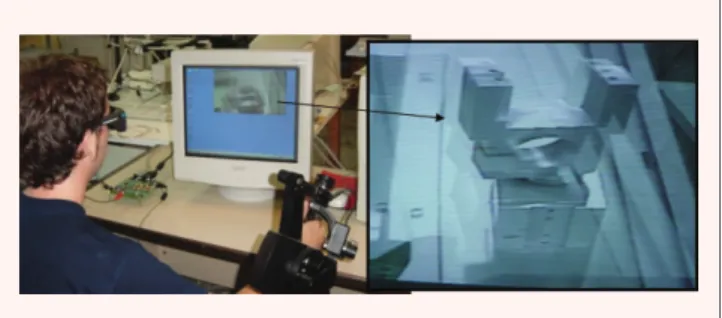
Figure 1 shows an example of binocular disparity images for telemanipulation, in which we can see a double view of the robot grip. Each view represents the image seen by each eye independently, and the blending of both views in the brain provides the operator’s spatial perception.
Motion parallax occurs because of the relative movement of the objects around us; those near us move faster than those located farther. This mechanism intervenes in the visualization of an object located 1 m away; hence, it starts becoming rele-vant as binocular disparity disappears. In teleoperation, this per-ception mechanism stirs into action when camera images move, e.g., if the camera is on a moving robot.
The third mechanism used to obtain depth information is known as image-realism cues, often described as monocular depth cues. Image realism is related to how we perceive our environment and the way in which we are accustomed to seeing objects. This information is related to aerial perspective, occlusion, lighting and shadows, relative object size, and surface textures. For example, in a picture, closer objects look larger and block the sight of other ones further away. In a movie, a texture gradient can be seen on the objects’ surface when they are in movement. Lights also provide redundant spatial information because object shadows and reflections appear according to the light conditions. High-quality monoscopic images in a well-illuminated environment have proved to be good enough for some teleoperation applications.
Advanced visual interfaces for telerobotics should include binocular images with the highest quality attainable. This allows the perception of spatial cues coming from binocular disparity and image realism. The addition of both cues gives the operator significant spatial perception.
Human Visual Field
The retinal visual field of an eye is the solid angle subtended by the spatial region, which projects light on the retina. It is a roughly 120°field of view for each eye. Figure 2 shows a hori-zontal section of the human visual field. The binocular field is the area within which objects are visible to both eyes, which is close to 50°. Slightly different projections on both retinas are produced within this common area. These images are fused in the brain. Within the stereoscopic visual field, points with posi-tive (or crossed) disparity and points with negaposi-tive (or uncrossed) disparity can be distinguished. The first type refers to those points beyond the place where the optical axes of our eyes inter-sect. The second type is made up of those located before such a place. Objects that fall on the corresponding points have zero binocular disparity. However, objects that fall on noncorres-ponding points produce disparity images. This disparity provides information about the object’s spatial location.
The main obstacles in reproducing the human visual field include the adequate simulation of image disparity and the reproduction of eye movements for accommodation and con-vergence. No video display can reproduce the eye movements
Figure 1.Example of stereoscopic images. Two views of the same part are displayed on the screen, and the shutter glasses select each part for the corresponding eye.
Monocular Field Left Eye
Crossed Disparity
Uncrossed Dispar
ity
Binocular Field
Monocular Field Right Eye
for accommodation and convergence. In real scenarios, eyes tend to accommodate and converge on the same point, which represents the point where our eyes are fixed; however, video displays dissociate these two by forcing the accommodation of the eyes to the surface of the display while the convergence is at a different distance. This implies that the ability to see binoc-ular depth on displays must be learned [9].
There is no consensus about the value of the maximum angular disparity that can be properly fused by visualizing binocular images. The variability of these findings is a result of the numerous factors affecting the correct image fusion, such as lighting conditions at the scene, contrast between objects, and the time that images are exposed. Most restrictive studies set the limit for crossed disparity at around 27-min arc and 24-min arc for uncrossed disparity [10]. Lipton suggests a maximum disparity of around 1.5° [11]. Experiments by Howard and Rogers [2] set limits of 4–7°for crossed disparity and 9–12°for uncrossed disparity. According to other works on telerobotic applications [1], limits can be fixed at 2° for crossed and uncrossed disparities. If image disparity is within these limits, then spatial perception will be properly achieved by the user. The brain can temporarily fuse stereoscopic images with a higher disparity, but this tires the user. The human threshold of angular disparity of is 1.5° is used to calculate the effective workspace in next section.
Monoscopic Versus Stereoscopic Images in Teleoperation
Numerous studies and experiments have been performed to compare the effectiveness of monoscopic images when compared with stereoscopic images. In [12], the authors demonstrate the usefulness of exploiting single 3-D stereoscopic visualization by using multiple monoscopic visual feedback in real-time teleoper-ation. Other experiments have also highlighted that the execution time for telemanipulation tasks is reduced by using stereoscopic images [13]. Studies performed by Cole et al. [14], [15] clearly suggest the superiority of stereoscopic viewing as opposed to monoscopic images in structure-assembly tasks consisting of a manipulator arm and nodes with structures inserted in node joints. The visualization system was based on polarized stereo-scopic images. It has been found that monostereo-scopic images have an effectiveness equivalent to stereoscopic ones only when the oper-ator has sufficient learning. This would appear logical because in any repetitive work the operator’s learning often allows skillful
task completion. A similar result is described in [16]. Unfortu-nately, repetitive work occurs rarely in teleoperation, as remote environments are usually unstructured.
In an interesting study [17], the effect of ocular distance reduc-tion is analyzed. The authors show that a 25% reducreduc-tion does not affect depth perception. The main feature of interest in this study is the reduction of disparity by closing the binocular cameras. Other works [18]–[20] reveal the complexity of the mechanisms used in stereoscopic image perception. Although stereoscopic images are generally more effective than the monoscopic ones, monoscopic data such as shadows and reflections can be as impor-tant as binocular disparity. For example, the image quality and contrast are found to be more relevant than binocularity for surgery tasks [21]. Some relevant considerations are also set forth concerning the discomfort sometimes felt by users due to distor-tions created by excessive disparity, ghosting, or conflicts between monoscopic and stereoscopic depth information.
Many studies have attempted to develop monoscopic image-viewing tools with an effectiveness equivalent to that of stereoscopic systems. Normally, they are based on the addition of graphic data to video images, such as virtual shadows or reference lines. The work by Kim et al. [22] suggests that the visual enhancement can bring significant improvements when reference lines are displayed or when the monoscopic display is defined with appropriate perspective parameters, such as ori-entation and zoom. These kinds of results, in which high-lighted monoscopic images are as useful as stereoscopic ones, show the complexity of depth-perception mechanisms. High-quality monoscopic video images and properly placed cameras can contain enough depth information to enable operators to perform teleoperated tasks skillfully.
Capturing Binocular Images for Telerobotics
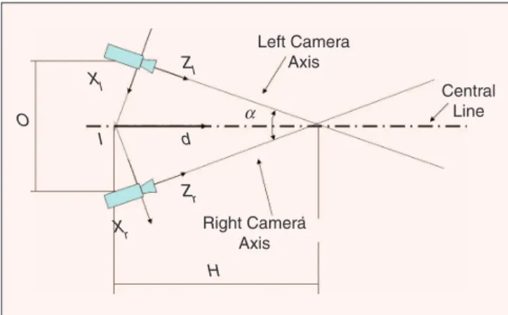
The first point to solve in designing the stereoscopic system is the binocular camera setup. The goal is to reproduce the human vision; therefore, a system with a configuration similar to human features may be the first solution to try. The simplest configuration can be made up of two cameras with a focal length equivalent to 50 mm, separated by 6–7 cm, and with a small angle between camera axes (less than 25°) or even with parallel axes. The angle of the camera axes is a key point that determines where the stereoscopic images are properly fused and thus what the effective remote workspace is.Calculation of the effective remote working area is required to know where stereoscopic images are properly fused. The visualization of stereoscopic images requires suitable binocular image capturing. Object appearance has to be natural. There-fore, video cameras must be adjusted and placed according to the object size and location to avoid excessive image dispar-ities. Figure 3 shows a typical binocular camera layout. Objects located at the same point where the camera axes intersect have zero disparity. If objects are placed nearer or farther, the dispar-ity increases. Nearer objects are seen with uncrossed dispardispar-ity and one that are farther away are seen with crossed disparity. Parameters of camera layout are the distance between the camera centers (O) and the angle between the camera axes (a). The distance between camera axes intersection and point I
No 3-D viewing system as effective
as the human eye has been
developed. However, a proper
spatial perception in
telemanipulation tasks can be
(point wherexaxes cameras intersect) is defined asH, which is related to the previous parameters asO¼H sin (a).
The following developments calculate image projection disparity for points located on the central line of the Figure 3. Points on this line are defined as (Xl,Yl,Zl) and (Xr,Yr,Zr) for
the corresponding reference system associated with the left and right cameras, respectively. Parameterdis defined as the distance between a point P of the central line and point I; the values of the aforementioned coordinates are therefore the following:
Xl ¼(Hd) sin (a=2), (1)
Yl ¼0, (2)
Zl ¼dcos (a=2), (3)
Xr ¼(dH) sin (a=2), (4)
Yr ¼0, (5)
Zr ¼dcos (a=2): (6)
Projections of point P are defined as (Xc,l,Yc,l) and (Xc,r,Yc,r)
for the left and right cameras, respectively. According to the pin-hole camera model projection, the values of these projections are as follows:
Xc,l¼f
Xl
Zl
¼f Hd
d tan (a=2), (7)
Xc,r¼f
Xr
Zr
¼f dH
d tan (a=2), (8)
wheref is the lens focal length.
Let projection disparity be the distance between the two camera projections of a point located on the central line. It is obtained as the absolute value of the distance between theX coordinates in both camera projections; i.e.,
projection disparity (d)¼2f tan (a=2)H d 1
: (9)
If camera axes are parallel (a¼0), then projection disparity dis given by (10).
Projection disparity (d)¼f O
d: (10)
The maximum acceptable disparity (MAD) can be defined as the maximum value of binocular image disparity that can be properly fused. MAD depends on the user-to-screen distance and the human thresholds for image disparity, which were discussed in the previous section. MAD was calculated by using a human threshold of 1.5°and a user-to-screen distance of 45 cm; it gives a maximum image disparity of 12 mm. It is assumed that any scale factor between camera and display coordinate systems is applied.
Figure 4 shows the evolution of the disparity versus object-to-camera distance for the points located at the central line. The horizontal line represents the value of the MAD (12 mm). The effective working area is the region in which the image disparity is inferior to the MAD. By looking at curve intersections, we can calculate the boundaries of the scene to be visualized. For Figure 4(a) (a>0), it would be possible to view all objects at a
distance ranging between point A (140 mm) and point B (665 mm). Figure 4(b) represents the disparity evolution when the camera axes are parallel. This represents an interesting case, as all objects beyondM (1,353 mm) can be properly fused. In this case, the region where binocular images are properly fused is larger; however, problems may arise at the minimum distance where objects fuse (point M), as it could be too high.
Equations (9) and (10) have to be analyzed according to the telerobotic application scenario to optimize the operator spatial perception. Parameters of this equation aref,a, andO(orH), and they must be adjusted according to the remote workspace features. Values of the Figure 4(a) aref ¼70 mm (images are a bit zoomed regarding direct human vision),O¼60 mm (simi-lar to human eye distance), and a¼15 (H ¼O=sin (a)¼ 232 mm). This setup allows for good depth perception for medium-size objects (objects easily manipulated by hand). These objects are properly fused if their distance from the binocular camera is between 140 and 665 mm. If a larger work-space is required, then the geometry of the binocular cameras has to be changed. The best solution is to use an automatic binocular camera vergence system. In [13], an automatic ver-gence system that controls a camera axis angle is tested. The goal of the vergence controller is to fix the intersection of the camera axes in the object shown in the center of the images. It implies that the camera vergence is modified to maintain the parameter H equal to the distance between the binocular camera and the central object. As a result, the working area is significantly increased, as image disparity is minimized.
Applications such as exploration or inspection where binocular cameras are placed over a mobile robot require a large workspace to enable object visualization. The simplest
Zl
Zr
Xr Xl
O
I d
α
H
Right Camera Axis
Left Camera Axis
Central Line
Figure 3.Layout of binocular cameras. The parameters are
angle between the camera axes (a), distance between the
centers of cameras (O), and the distance between point I and the intersection of camera axes (H). These parameters are
related according to O¼Hsin(a).
solution is to place the cameras parallel to each other (a¼0). Therefore, all objects farther than a predefined length (M) are properly fused as shown in Figure 4(b). According to [17], the camera distance (O) can be reduced up to 25% without signifi-cant deterioration of perception, and similar results are obtained also in [21]. This makes it possible to reduce parame-ter O and, consequently, the minimum distance (M) is also reduced as shown in (10).
On the other hand, applications such as minimally invasive surgery are characterized by a reduced working space. In this case, the main problem is the size of the endoscope binocular camera. Here, the best option is to use very small cameras and adapt the focal length according to (10) to obtain a proper visu-alization. Therefore, a highly reduced endoscope can be used, and scene objects can be significantly zoomed. As an example, the da Vinci system [23] uses a set of different reduced binocu-lar camera lenses that provide good stereoscopic visualization of the internal organs with a reduced-size endoscope.
Additional factors, such as object distance correction or image distortion, have to be considered to properly visualize the stereoscopic images. Objects far from the central area of the image have a higher disparity [24]. Telesurgery is a good example of object distortion due to the short distance between
organs and cameras. Techniques to correct this problem are reviewed in [25]. An example of distance correction by using head-mounted displays (HMDs) is described in [26].
Stereoscopic Visual Interfaces
The second relevant point in the visualization of stereoscopic images is the selection of the proper visual interface. The ideal video interface in a teleoperated system would show informa-tion in a similar way to that of common human vision. Simu-lating full binocular vision requires technology beyond what is currently available. No current display can meet all the specifi-cations required to achieve proper depth perception. This fact explains why such a great variety in stereoscopic devices exists to date. A great deal of literature is devoted to the detailed explanation of this kind of equipment [27]–[31]. Stereoscopic devices can be classified according to their functionalities.
u Binocular devices:They usually use additional materials like glasses or a helmet to show a different image to each eye.
u Autostereoscopic devices:They show a different image to each eye without the need of additional devices. u Immersive devices:They make use of broad scenes where
the depth perception is attained by covering the whole visual field.
Binocular Devices
The main characteristic of binocular devices is that the observer needs to use an additional device to be able to properly view the stereoscopic images. An extra external element, such as glasses or helmet, is required to separate the images for each eye. These are in turn divided into parallel devices, which show images simultaneously to both eyes, and sequential devices, which show images alternately. The most popular devices in this group are HMDs, shutter glasses, and polarized glasses.
35
30
25
20
Projection Dispar
ity (mm)
Projection Dispar
ity (mm)
Projection Disparity Evolution
Projection Disparity Evolution
Object-to-Camera Distance (mm)
A B M
400 600 800 1,000 1,200 1,400 1,600 1,800 2,000 200 400 600 800 1,000 1,200 1,400
(a)
Object-to-Camera Distance (mm)
(b) Maximum
Acceptable Disparity
Maximum Acceptable Disparity 15
10
5
0
35
30
25
20
15
10
5
0
Figure 4.Calculation of the effective working area according to image disparity. (a) (a>0), objects located within the distance
between A and B have a projection disparity inferior to the MAD. (b) (a¼0), all objects located further than distance M are
properly fused.
The simplest binocular stereoscopic
configuration setup can be made up
of two parallel cameras that are
6
–
7 cm apart with 50 mm focal
HMDs are like glasses or a helmet but with different video displays for each eye. They are commonly used in virtual real-ity applications and normally include a mechanism that follows the movement of the observer’s head; it allows the view point of the visualized images to vary. For some interesting examples of telerobotic interfaces based on these devices, see [26] and [32]–[34]. Another interesting example of binocular display is the da Vinci surgical system developed by Intuitive Surgical Inc. [4]. Figure 6 shows the surgeon’s console including a binocular display with the endoscope stereoscopic images [23]. Active shutters are based on different frames being shown to the left and right eye alternately. The user wears shutter glasses synchronized with the display that shows the images. Liquid crystal shutter glasses are the most commonly used. The shutters flip between opaque and clear so that only the left eye can see the screen when the left-eye image is being dis-played and vice versa. High-quality images are achieved when the display refreshment frequency is higher than 80 frames per second and a proper pair of glasses is used. CrystalEyes are the most well-known shutter glasses, which are manufactured by StereoGraphics [11]. This interface has been used in some tele-robotic systems such as Rotex [35], the first remotely con-trolled space robot system, and Robtet [5], a telerobot for live-line maintenance tasks (Figure 7).
Other binocular systems are based on displaying polarized or colored images. The user wears glasses with the proper fil-ters (polarized or colored) to show the corresponding image
for each eye. The results are high-quality stereo images suitable for a large audience. 3-D movies are usually based on these interfaces. A commercial example of this system is the Monitor ZScreen by StereoGraphics, which comprises a modulating stereoscopic panel and passive polarized eyewear. The panel is attached to a standard cathode ray tube (CRT) monitor for properly polarizing the images, and the eyewear separates the left and right eye images accordingly. This visualization interface has been successfully applied at Carnegie Mellon University (CMU) for guiding the K-10 robot developed by NASA-Ames [6]. As shown in Figure 8, a user visualizes the stereoscopic images provided by the binocular camera mounted on top of the vehicle. This telerobot is designed for Lunar and Martian mineral prospecting.
Autostereoscopic Devices
Autostereoscopic devices are used for viewing different images without the need of any additional devices. This type of equip-ment usually relies on a geometric configuration. The observer has to view from a given position to ensure proper image visual-ization, which is a major disadvantage of this type of device, as even small movements make the images fuzzy. The most impor-tant autostereoscopic devices are the parallax barrier and lenticu-lar sheets. There are other systems such as holographic displays, volumetric or multiplanar displays, and autostereograms applied
(a) (b)
Figure 6.Da Vinci surgical system. (a) Stereoscopic endoscope to show a zoomed view of the organs. (b) The surgeon’s console with a binocular display. (Photo courtesy of Intuitive Surgical Inc., 2008.)
(a) (b)
Figure 7.Telerobotic system for live-line maintenance tasks. (a) Operator’s cabin with a stereoscopic display based on active shutter glasses. (b) Remote robot executing a replacement task.
(a) (b)
Figure 8.Telerobotic system developed for exploring application. (a) K-10 robot developed by NASA-Ames. (b) Operator interface that includes a stereoscopic display based on polarized images.
(a) (b)
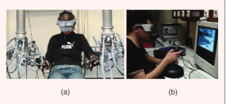
Figure 5.Examples of stereoscopic displays: (a) HMD with tracker integrated in a multimodal telerobotic system (Technische Universitat Munchen, Germany) and
(b) stereoscopic interface for guiding a robot by using active
to the visualization of 3-D pictures. A parallax barrier is a vertical slit plate placed in front of a display to block a part of the screen shown to each eye. The screen displays two images divided into vertical strips. Each eye can see only the corresponding strips because of the slit plate performance. The observer’s eyes must be placed at the proper position to avoid the blending of the strips. Lenticular sheets are based on an array of cylindrical lenses that generate a 3-D image by showing different vertical sections to each eye. The observer’s head must be placed at a predefined position to properly see the 3-D image; otherwise the cross sec-tions will be overlaid as the head moves. Unfortunately, these technologies do not offer good performance in current telero-botic applications, but significant improvements have been made to them. Future systems may be based on autostereoscopic images, as no additional user equipment is required. The main question to be solved consists in detecting the user’s eye position so that the images can be properly shown to him or her. This will help overcome current problems in teleoperation.
Immersive Devices
These systems are used to show a 3-D environment to the observer. To do so, they use the whole visual field as well as the motion parallax. There are two kinds of systems: curved-screen theaters and flat-curved-screen walls. The curved-curved-screen thea-ter is usually made up of large cylindrically or spherically curved displays showing images from multiple projectors, which are edge-blended. It creates a strong sense of immersion even without stereoscopic images. Flat-screen walls are large flat-screen displays using images from multiple projectors and showing monoscopic or stereoscopic images. They look like a room where the walls are screens showing different environ-mental scenes. Few examples include [36] and [37], where these systems are mainly used for virtual reality applications. The advanced degree of interaction with the operator (voice, gestures, strengths, etc.) makes virtual reality systems attractive to telerobotics applications, such as the control of complex sys-tems in which many remote robots must be controlled.
Conclusions
Efficient telemanipulation tasks can be undertaken by using stereoscopic video interfaces. These interfaces allow the oper-ator to achieve adequate depth perception from the remote environment. Image disparity and image quality are the key factors in designing a stereoscopic video interface. When both are appropriate, the operator has an excellent perception for the performance of telemanipulation tasks. High-quality im-ages show spatial cues such as shadows and reflections, which provide additional information for 3-D location of the object. Binocular image disparity has to be limited in accordance with human visual perception. Calculations for the suitable design
of a stereocamera layout have been performed to correspond with human capabilities. Working within the aforementioned conditions has resulted in a more precise and effective telemani-pulation performance. Although current stereoscopic interfaces do not allow for the reproduction of human vision, significant improvements are being made every day, thus making it possible to design interfaces with excellent features that offer operators better visualization of remote teleoperation scenes.
Acknowledgments
We thank Prof. Gregg Podnar from Carnegie Mellon Univer-sity, Prof. Kesavadas from University at Buffalo, and Prof. Jose M. Sebastian from Universidad Politecnica de Madrid for their fruitful comments and discussion on stereoscopy. This work has been partially supported by the Spanish Ministry of Ciencia e Innovacion under the grant DPI2006-06493.
Keywords
Telerobotics, stereoscopic interfaces, binocular disparity, telepresence.
References
[1] M. Ferre, R. Aracil, and M. Navas, ‘‘Stereoscopic video images for tele-robotics applications,’’J. Robot. Syst., vol. 22, no. 3, pp. 131–146, 2005. [2] I. P. Howard and B. J. Rogers,Binocular Vision and Stereopsis. London,
U.K.: Oxford Univ. Press, 1995.
[3] R. C. Goertz, ‘‘Manipulators systems development at ANL,’’ in Proc. 12th Conf. Remote Systems Technology, American Nuclear Society, 1964, pp. 117–136.
[4] G. S. Guthart and J. K. Salisbury, ‘‘The intuitive telesurgery system: Overview and application,’’ inProc. 2000 IEEE Int. Conf. Robotics and Automation, pp. 618–621.
[5] R. Aracil, M. Ferre, M. Hernando, E. Pinto, and J. M. Sebastian, ‘‘Tele-robotic system for live-power line maintenance: ROBTET,’’Contr. Eng. Pract., vol. 10, no. 11, pp. 1271–1281, 2002.
[6] G. Podnar, J. Dolan, A. Elfes, M. Bergerman, H. B. Brown, and A. D. Guisewite, ‘‘Human telesupervision of a fleet of autonomous robots for safe and efficient space exploration,’’ in Proc. ACM/IEEE 1st Annu. Conf. Human-Robot Interaction, 2006, pp. 325–326.
[7] D. C. Hood and M. A. Finkelstein, ‘‘Sensitivity to light,’’ inHandbook of Perception anad Human Performance. New York: Wiley, 1986.
[8] A. C. Guyton and J. E. Hall,Textbook of Medical Physiology. Philadelphia, PA: Sanders, 2000.
[9] J. Baker, ‘‘Generating images for a time-multiplexed stereoscopic computer graphics system,’’ inProc. Int. Soc. for Optical Engineering, True 3D Imaging Techniques and Display Technologies, 1987, vol. 761, pp. 44–52. [10] Y. Y. Yed and L. D. Silverstein, ‘‘Limits of fusion and depth judgment in stereoscopic color displays,’’Hum. Factors, vol. 32, no. 1, pp. 45–60, 1990.
[11]The Crystal Eyes Handbook, StereoGraphics Corp., San Rafael, CA, 1991.
[12] W. Fung, W. Lo, Y. Liu, and N. Xi, ‘‘A case study of 3D stereoscopic vs. 2D monoscopic tele-reality in real-time dexterous teleoperation,’’ in
Proc. Intelligent Robots and Systems 2005 (IROS 2005), pp. 181–186. [13] A. Bernardino, J. Santos-Victor, M. Ferre, and M. A. Sanchez-Uran,
‘‘Stereoscopic image visualization for telerobotics: Experiments with active binocular cameras,’’ inAdvances in Telerobotics(Springer Tracts in Advanced Robotics), vol. 31, M. Ferre, M. Buss, R. Aracil, C. Mel-chiorri, and C. Balaguer, Eds. New York: Springer-Verlag, 2007, pp. 77–90.
[14] R. E. Cole, J. O. Merritt, S. Fore, and P. Lester, ‘‘Remote manipulator tasks impossible without stereo TV,’’ inProc. Int. Soc. for Optical Engineer-ing, Stereoscopic Displays and Applications, 1989, vol. 1256, pp. 18–27.
Binocular image disparity has to be
[15] R. E. Cole and D. L. Parker, ‘‘Stereo TV improves manipulator performance,’’ inProc. Int. Soc. for Optical Engineering, Three-Dimensional Visualization and Display Technologies, 1990, vol. 1083, pp. 255–265. [16] D. Drascic, P. Milgram, and J. Grodski, ‘‘Learning effects in
telemani-pulation with monoscopic versus stereoscopic remote viewing,’’ inProc. IEEE Int. Conf. Systems, Man, and Cybernetics, 1989, pp. 1244–1249. [17] S. R. Ellis, J. M. Fishman, C. J. Hasser, and J. D. Stern, ‘‘Effect of
reduced stereoscopic camera separation or ring placement with a surgi-cal telerobot,’’ inProc. Int. Soc. for Optical Engineering, Stereoscopic Displays and Virtual Reality Systems XII, 2005, vol. 5664, pp. 372–379.
[18] W. F. Reinhart, R. J. Beaton, and H. L. Soyder, ‘‘Comparison of depth cues for relative depth judgments,’’ inProc. Int. Soc. for Optical Engineer-ing, Stereoscopic Displays and Virtual Reality Systems, 1990, vol. 3639, pp. 12–21.
[19] L. Stelmach, W. J. Tam, and D. Meegan, ‘‘Perceptual basis of stereo-scopic video,’’ inProc. Int. Soc. for Optical Engineering, Stereoscopic Displays and Virtual Reality Systems, 1990, vol. 3639, pp. 260–265.
[20] J. Hsu, Z. Pizlo, D. M. Chelberg, C. F. Babbs, and E. J. Delp, ‘‘Isssues in the design of studies to test the effectiveness of stereo imaging,’’IEEE Trans. Syst., Man, Cybern. A, vol. 26, no. 6, pp. 810–819, 1996. [21] F. Tendick, R. W. Jennings, G. Tharp, and L. Stark, ‘‘Sensing and
manipulation problems in endoscopic surgery: Experiments, analysis and observation,’’Presence, vol. 2, no. 1, pp. 66–81, 1993.
[22] W. S. Kim, S. R. Ellis, M. E. Tyler, B. Hannaford, and L. W. Stark, ‘‘Quantitative evaluation of perspective and stereoscopic displays in three-axis manual tracking tasks,’’ IEEE Trans. Syst., Man, Cybern., vol. 17, no. 1, pp. 418–425, 1987.
[23] Intuitive Surgical Inc. (2008). 3D Vision System [Online]. Available: http://www.intuitivesurgical.com/products/davincisurgicalsystem/3d.aspx [24] V. S. Grinberg, G. Podnar, and M. W. Siegel, ‘‘Geometry of binocular imaging,’’ inProc. IST/Int. Soc. for Optical Engineering Symp., Stereoscopic Displays and Virtual Reality Systems, 1994, vol. 2167, pp. 56–65. [25] F. Shevlin, B. McCullagh, D. Eadie, M. Navas-Herreros, and C.
Rabaud, ‘‘Stereoscopic 3-D acquisition, processing, and display for telero-botic applications,’’ inAdvances in Telerobotics(Springer Tracts in Advanced Robotics), vol. 31, M. Ferre, M. Buss, R. Aracil, C. Melchiorri, and C. Balaguer, Eds. New York: Springer-Verlag, 2007, p. 91105.
[26] H. Baier, M. Buss, F. Freyberger, and G. Schmidt, ‘‘Interactive stereo vision telepresence for correct communication of spatial geometry,’’Adv. Robot., vol. 17, no. 3, pp. 219–233, 2003.
[27] M. McKenna and D. Zeltzer, ‘‘Three dimensional visual display sys-tems for virtual environments,’’Presence: Teleoperators and Virtual Environ-ments, vol. 1, no. 4, pp. 421–458, 1992.
[28] N. I. Durlach and A. S. Mavor,Virtual Reality Scientific and Technological Challenges. Washington, DC: National Academy Press, 1995.
[29] M. Halle, ‘‘Autostereoscopic displays and computer graphics,’’Comput. Graph., vol. 31, no. 2, pp. 58–62, 1997.
[30] J. W. Roberts and O. Slattery, ‘‘Display characteristics and the impact on usability for stereo,’’ inProc. Int. Soc. for Optical Engineering, Stereo-scopic Displays and Virtual Reality Systems, 2000, vol. 3957, pp. 128–137. [31] D. Wright, ‘‘A survey of projection-based immersive displays,’’ inProc.
Int. Soc. for Optical Engineering, Stereoscopic Displays and Virtual Reality Systems VII, 2000, vol. 3957, pp. 482–492.
[32] S. Lee, D. Choi, M. Kim, C. Lee, and J. Song, ‘‘Human and robot integrated teleoperation,’’ in Proc. IEEE Int. Conf. Systems, Man, and Cybernetics, 1998, pp. 1213–1218.
[33] H. Baier, F. Freyberger, and G. Schmidt, ‘‘A high fidelity interactive stereo vision,’’ inProc. 2001 Workshop on Advances in Interactive Multimo-dal Telepresence Systems, 2001, pp. 32–42.
[34] H. Hu, J. Li, Z. Xie, B. Wang, H. Liu, and G. Hirzinger, ‘‘A robot arm/hand teleoperation system with telepresence and shared control,’’ in
Proc. 2005 IEEE/ASME Int. Conf. Advanced Intelligent Mechatronics, 2005, pp. 1312–1317.
[35] G Hirzinger, B. Brunner, J. Dietrich, and J. Heindl, ‘‘Sensor-based space robotics-ROTEX and its telerobotic features,’’IEEE Trans. Robot. Automat., vol. 9, no. 5, pp. 649–663, 1993.
[36] E. Freund and J. Robmann, ‘‘Projective virtual reality as a basis for on-line control of complex systems-not only-over the Internet,’’ J. Robot. Syst., vol. 22, no. 3, pp. 147–155, 2005.
[37] A. Kheddar, E. Neo, R. Tadakuma, and K. Yokoi, ‘‘Enhanced teleop-eration through virtual reality techniques,’’ in Advances in Telerobotics
(Springer Tracts in Advanced Robotics), M. Ferre, M. Buss, R. Aracil, C. Melchiorri, and C. Balaguer, Eds., vol. 31. New York: Springer-Verlag, 2007, pp. 139–159.
Manuel Ferre obtained his Laurea degree in control engi-neering and electronics in 1992 and Ph.D. degree with hon-ors in automation and robotics in 1997 from the Universidad Politecnica de Madrid. In 1997, he worked as a postdoctoral fellow in the Human-Machine System Laboratory of Massa-chusetts Institute of Technology. Since 2000, he has been a professor Titular at the Universidad Politecnica de Madrid. He has participated and coordinated several research projects in robotics and automatic control, both at national and inter-national programs. His research interests focus on automatic control and advanced telerobotics. He has three patents of haptic devices and stereoscopic video cameras. He has auth-ored many papers on bilateral control and human interfaces for teleoperation and is coeditor of Advances in Telerobotics (Springer STAR series). He is a Member of the IEEE and serves as chair of the IEEE Robotics and Automation Society (RAS) Technical Committee on Telerobotics.
Rafael Aracil received his degree in electrical engineering in 1971 and Ph.D. degree in control engineering in 1975 from the Universidad Politecnica de Madrid. He is currently full professor and head of the robotics and intelligent machines at the same university. His main research interest is in the area of advanced manufacturing, robotics, and image processing. Currently, he is working on the development of robots for news applications and intelligent teleoperation for different industrial enterprises. He is the author of several books, papers, and communications in the cited topics. He has worked in several European Union (EU)-funded projects such as ESPRIT, BRITE, and EUREKA.
Miguel A. Sanchez-Uran received his Laurea degree in control engineering and electronics in 1992 and Ph.D. degree with honors in electronics in 1998 from the Univer-sidad Politecnica de Madrid. He was with the Telefonica Department for Research in 1992–2001. Currently, he is a professor at the Electrical Engineering Department of the Universidad Politecnica de Madrid. His research interests include automatic control and advanced telerobotics, haptics, and signal processing. He is working on different projects and developments in these areas. He has been the author of several papers on human interfaces for teleoperation.