New Approach on the Cold Welding of Metals: Application to
Aluminium Bars
D. Iordachescu , M. Iordachescu , M. Blasco , J.L. Ocana
Centro Laser, Universidad Politecnica de Madrid, Ctra. de Valencia, km. 7,3; Campus Sur U.P.M. "LaArboleda", 28031 Madrid, Espana,
Tel: +34 91 3365540, [email protected]
ETSI Caminos, Canales y Puertos, Dep. de Ciencia de Materiales, Universidad Politecnica de Madrid, C/Profesor Aranguren s/n, 28040 Madrid, Espana,
Tel: +34 664687919, [email protected]
Area Tematica: Ingenieria de Fabrication
Resumen
La soldadura por frio por presion es un proceso de fabrication de empalme en estado solido con varios usos importantes, pero carente en sus fundamentales. Este papel presenta un nuevo acercamiento de la investigation en el campo, trayendo contribuciones originales teoricas y practicas al conocimiento del principio de la soldadura en frio y creando las bases para el desarrollo de los nuevos procesos que tratan los materiales modernos. El acercamiento se basa en un FEM capaz para predecir el comportamiento material durante la deformation, considerando varias condiciones introducidos por el codigo usado: analisis estatico no linear, tension grande y desviacion grande, dislocaciones prescritas. La correlation entre las tensiones y la deformation del material ha sido tratada luego. Las dimensiones y las caracteristicas de la zona afectada mecanica - MAZ (desarrollado en el material debido al proceso de deformation) estan tambien alcanzados.
Palabras Clave: modelo con elemento finito, soldadura por frio, deformation pldstica, empalme de aluminio
Abstract
Cold pressure welding is a solid state joining manufacturing process with several important applications, but with gaps in its fundamentals. This paper presents a new approach of the research in the field, bringing both theoretical and practical original contributions to the knowledge of the cold welding principle and creating the bases for the development of new processes addressing modern materials. The approach is based on a FEM capable to predict the material behaviour during the up-setting, considering several constrains introduced by the used FEA code: non-linear static analysis, large strain and large deflection, prescribed displacements. Correlation between stresses and material deformation is further addressed. The dimensions and characteristics of the Mechanical Affected Zone - MAZ (developed in the material due to the up-setting process) are identified.
Keywords: finite element modelling, butt cold welding, plastic deformation, aluminium joints
1. Introduction
Cold welding process can be easily and comfortably achieved, being practically the
result of the pressing force applied between two metal sheets appropriately and carefully
cleaned. This process requires important materials deformation degrees (usually over
times greater than the maximum yield strength of the material. Cold pressure welding
can be achieved mainly by two methods: spot welding and butt welding. In both cases,
similar or heterogeneous welded joint can be obtained. Easy deformable metals as
Aluminium or Copper can be cold-welded, but the process can be also achieved
between dissimilar metals (Aluminium-Stainless Steel, Aluminium-Titan etc.), as well
as between theirs alloys. Wires and bars can be joined using butt cold welding
2. Principle of Pressure Butt Cold Welding
Butt cold pressure welding rises very interesting theoretical and practical problems
regarding the minimum value of the squeezing force that ensures the joint achievement,
the material flowing, the material cold hardening (increasing during the process), and
the yield stress and cold hardening interdependency . A diagram that illustrates the
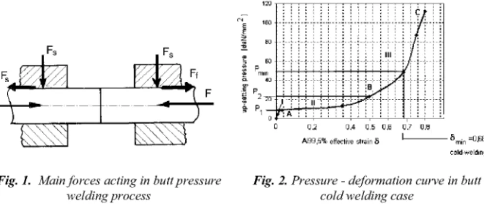
main forces acting in butt cold pressure welding is presented in Fig. 1.
Comparing with hot pressure welding, when the parts extremities are heated by Joule
effect and the pressure is approximately/) = (0.1 ... 0.2)ac, in butt cold welding case the
pressure is p = (8 ... 10)ac, meaning that, for the same material, a 100 times bigger
pressing force is applied [2].
^m
ife
0.2
AJ99.51 effective strain S
0.4 0,5 0.6 0.7 0.8
I
cold-welding
Fig. 1. Main forces acting in butt pressure welding process
Fig. 2. Pressure - deformation curve in butt cold welding case
The explanation is that the specific compression pressure depends on the deformation
needed value, S. Fig. 2 presents the correspondence between the material deformations
and the applied pressure , illustrating the practical behaviour of the material during
the deformation process. The b-c section of the curve represents the material cold
hardening area, where a high deformation is obtained only if using pressure values
bigger than the material yield strength. This is the area where the cold welding is
Due to recent developments in engineering software, which made possible the
modelling of the physical processes and their mechanisms easier than ever, a FEA for
aluminium butt cold welding was developed by the authors considering the material
elasto-plastic constitutive law.
3. Deformation process modelling of the bars on butt-cold welding
The constitutive elasto-plastic model has involved the Von Mises criterion, which was
used to define the effective stress.
As time curve (specific for the COSMOS - NSTAR code ), the material constitutive
law (stress-strain curve) was used for introducing the isotropic non-linear material.
The material used to simulate the butt cold welding process was 99.5% Al with different
description: the linear-elastic part was introduced by the Young modulus E = 6.9 10+I(>
[N/m2] and the Poisson ratio v= 0.33, whilst the plastic behaviour was described by the
strain-stress relation illustrated in Fig. 3
Fig. 3. Strain-stress characteristic curve Fig. 4. Butt-cold welding model: a) sketch of the
of 99,5% Aluminium butt cold welding; b) finite element model; c)
adapted mesh for the critical area
Fig. 4 presents the sketch of butt cold welding of aluminium bars and the finite element
model used for analyzing and interpreting this process, described by:
- The geometry: two bars (99,5% Al, 10 mm diameter, 40 mm length each of them)
were isothermal upset. The symmetry reasons allowed that only a quarter of bars joint
to be modelled. The clamping dies were modelled as being rigid, with sticking friction
- The mesh defined geometry: the main part of the finite element mesh contains 4-noded
PLANE2D axis-symmetric displacement pressure elements. Near the die corner,
where the rollover was expected to occur, the elements have triangular shape,
accommodating the deformation mode. Gap elements were used to model the contact
between the bar and the clamping die, using an additional line surface (Fig.4,b).
- The constraints applied on the finite element model were: non-linear static analysis,
elasto-plastic material model, large strain and large deflection, prescribed
displacements.
- The loads of the model: pressure-displacement elements of the bars.
- The Newton-Raphson iterative method was used to ensure at any time step the stiffness
matrix convergence of the model.
4. Mechanical Affected Zone, MAZ - FEA & Experiments
After completing the finite element model analysis of the butt cold welding process, the
results related to the equivalent stress distribution on two main directions, along x and
y-axis in the Aluminium bars were analyzed.
The maximum values of the equivalent stresses are recorded in the joint area, indicating
that the initial structure of the base material has changed due to the plastic deformation
process. The stress values in the bar, in the clamps proximity are decreasing with the
distance from the cold welded joint to minimum values around 6.5 107 N/m2 (at 0,02
m), corresponding to the starting point of the base material plastic deformation and cold
hardening of it.
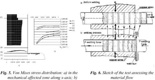
The pressure influence was studied by analysing the image of the MAZ on the x-axis, at
different distances from the joint, on B1-B5 lines (Fig. 5,a). The results are presented in
Fig. 5,b, indicating that the stress distribution decreases from the Bl line (bar cold weld)
to the B5 line (situated at 0,02 m from the cold weld). The maximum values of the
equivalent stresses are recorded in the joint area, outside the clamps, indicating that the
base material initial structure has changed due to the plastic deformation process. As
general conclusion regarding the B1-B5 lines, the stress values are decreasing on radial
weld burr
a)
Fig. 5. Von Mises stress distribution: a) in the Fig. 6. Sketch of the test assessing the
mechanical affected zone along x-axis; b) material flow stress distribution chart along x-axis
Cold pressure welding experiments were performed by using a 200 kN hydraulic press.
The pressed material displaces inside and outside the clamping area and the bars
material becomes harder, finally producing the cold welded joint. As Fig. 6,a, shows,
several small diameter copper wires were introduced in the bars before welding
After cold welding achievement (Fig. 6,b), due to the copper wires deformation, the
image of the deformation process inside the bars is obtained, the slope of the strains and
stresses curves being practically illustrated by the shapes of these deformed wires.
after welding "ill I! i i < i i W w material displacement
Fig. 7. Images of butt-cold welded bars and of the deformed copper wires
Fig. 7 presents the macroscopic image of a cold welded joint obtained at room
temperature, after applying the necessary up-setting force and the image of the
deformed copper wires.
5. Conclusions
- The finite element model developed for the butt cold welding process for aluminium
bars, 10 mm diameter is capable to describe the material deformation during upsetting.
This model can be used as starting point for future research on the achievement of
dissimilar cold welded joints.
- Theoretical and experimental results confirm that the material flows inside of the
clamping area, producing the cold hardening phenomenon, whose intensity decreases
when the distance from the weld increases.
- The material flowing inside the aluminium bars is more evident and rapid along the
y-axis, due to the material mechanical anchoring phenomenon on clamps contact line and
to the quicker surface cold hardening.
6. References
V. Georgescu, M. Iordachescu, B. Georgescu, Practica sudariiprin presiune la rece
(Cold Welding Practice), Editura Tehnica, Bucuresti, 2001.
M. Iordachescu, D. Iordachescu, E. Scutelnicu, J. L. Ocana: Sci. Technol. Weld. Join., 2007,12, (5), 4 0 2 - 4 0 9 .
Aluminum and its alloys, Aluminum Association, Inc., 818 Connecticut Avenue,
N. W., Washington, D.C.20006, June, 2000.
J.V. Fernandes, J.J. Gracio, J.H. Schmidt, in Teodosiu C , Raphanel J.L., Large
plastic deformation: Fundamental aspects and applications to metal forming,
Balkema, Rotterdam, 1993, pp 219.
COSMOS/M2.5, User'Manual, 1999.
M. Iordachescu, E. Constantin, Aluminium Plastic Deformation Process in Butt