Abstract—The pose of a robot is an essential information for manipulating, scheduling and monitoring tasks. This paper presents a novel system architecture and algorithm for indoor robot pose estimation. Previous robot pose estimation systems have limitations in terms of computational cost, accuracy, price or safety. Therefore, we propose a cheap and easy-to-use solution which needs only one or two laser pointers mounted on the robot pointing vertically towards the ceiling plane and a fixed low-cost camera. The proposed system is suitable for applications that demand very high localization accuracy. It can be potentially used for health care and surveillance applications. The experimental results clearly show that the proposed method is able to achieve high speed and high precision. The average pose estimation error is 14 mm in an area of about 24 m2 and the algorithm runs at 27 Hz.
Index Terms— robot; pose estimation; localization; laser; camera
I. INTRODUCTION
Today, as a rapidly growing field, robotics plays an important role in many sectors, such as industry, military, personal service, entertainment and smart homes. One of the fundamental technological problems in robotics is localization. The information about the position and orientation (pose) of robots is essential for planning and scheduling. The followings are basic requirements for a robot localization system.
Accurate position and orientation estimation: identifying the pose of the robot is a necessary step to perform location-based tasks. The accuracy requirements depend on the working environment and the tasks to be performed. Quick response: to achieve real-time performances, the estimated pose should be updated at a high rate and with low latency.
Simple initial set up: the initial set up should not be tedious, so that the system can start working in new environments without much effort.
High reliability, robustness, safety, scalability and low cost: the system should work under non-ideal conditions and be easily extended to larger areas. It should not introduce risk factors to people living or working in the same environment. For example, in case of using laser technology, the laser maximum power should be limited to eye-safe values. Also, the cost should be reasonable.
Manuscript received June 10, 2015. Juan Li acknowledges the China Scholarship Council for her scholarship.
Juan Li, Paula Tarrío and José Ramón Casar are with Technical University of Madrid, 28040, Spain (e-mail: {li.juan, paula, jramon} @grpss.ssr.upm.es).
Hamid Aghajan and Wilfried Philips are with TELIN-IPI-iMinds, Ghent University, 9000, Belgium (e-mail: {Hamid.Aghajan, Wilfried.Philips} @ugent.be). Hamid Aghajan is also with Ambient Intelligence Research (AIR) Lab, Stanford University, CA, USA.
In this paper, we propose a new concept for indoor robot position and orientation estimation which combines one or two off-the-shelf laser pointers and a camera to provide a low-cost, fast and highly accurate solution. It has also the potential of being scalable to multi-agent (multi-robot) scenarios.
The paper is organized as follows: A review of related work is presented in Section II. Section III presents the novel architecture of the proposed system. Section IV describes the pose estimation algorithm. We then show the experimental results in Section V and Section VI concludes the paper.
II. RELATED WORK
A conventional localization system for outdoor robot applications is the Global Positioning System (GPS). However, it doesn’t work well in indoor environments due to the signal loss from the satellites. For indoor localization, inertial navigation systems (INS) [1] are traditionally used to track the position and orientation without external aid. However, these systems suffer from integration drift, so periodical corrections from other type of localization system are needed. In order to overcome the drawbacks of GPS and INS, a variety of external sensors have been employed, such as cameras, lasers, sonar, radio frequency (RF) technologies, etc.[2-9].
Vision-based methods, which use image processing methods to calculate the robot pose relative to the world coordinate frame, are receiving an increasing attention in the last years. According to the way the camera is deployed, most of the vision-based systems can be classified into front-view vision systems, ceiling-view vision systems and global vision systems.
In front-view vision systems, the robot carries a forward-looking camera and then natural landmarks or artificial landmarks are used to localize the robot. In [2], the authors used scale-invariant feature transform (SIFT) key points as natural landmarks. The algorithm ran at around 2 Hz for 320×240 images with a Pentium III 700 MHz processor. It could achieve an accuracy of 4.4 cm.
In ceiling-view vision systems, the camera is mounted on the robot with its optical axis pointing vertically towards the ceiling. The advantages of using ceiling vision are: a) the ceiling plane is relatively simple and not affected by dynamic interference, for example, moving objects, unlike the scenes in front-view vision systems; b) no scale change occurs in the image sequences, because the distance between the robot and the ceiling is fixed. Hwang et.al [3] proposed an approach using an upward-looking monocular camera to perform simultaneous localization and mapping (SLAM) of a mobile robot by detecting corners, lamps and door features. The
A Novel Laser-vision Combined Approach to Indoor
Robot Pose Estimation
experimental results showed that the mean error of this approach was 10 cm and the algorithm ran at around 6 Hz. A recent research by Lin and Chen [4] presented a robot pose estimation system based on deploying a 2D barcode landmark on the ceiling and mounting a camera vertically on the robot. This method was shown to achieve a high accuracy (less than 1.5 mm), with a mean error in the heading angle of less than 1 degree. The algorithm ran at about 12 Hz for 720×576 images. On the downside, various artificial landmarks have to be deployed in the ceiling and their positions have to be measured accurately. Additionally, at least one marker has to be in the camera view to make the system work.
A global vision system is defined as a system that has a global camera placed in a certain position from where it can monitor the movement of the robot. For example, in [5], robots are controlled by detecting the artificial markers placed on the robot using images from a global camera.
Generally speaking, vision-based methods can provide highly accurate estimations. At the same time, they are more computational-intensive than other pose estimation systems and may be unreliable due to illumination variation and dynamic environments.
Range-finding methods, which measure the distance from the observer to a target, are popularly used for 3D mapping and obstacle avoidance. Ultrasound, laser and radar are included in this category. Light Detection and Ranging (Lidar) has been applied for robot applications in both outdoor [6] and indoor [7] environments. In [7], the mean distance error is 11.1cm and the mean angle error is 0.89 degree. However, range-finding methods have limitations in environments that have few reflective surfaces.
RF technologies, including active and passive identification (RFID), Bluetooth and WiFi, have a wide number of applications. Indoor environments are challenging for radio-based localization due to signal reflection, diffraction and scattering, which reduce the measurement accuracy to meter level for Bluetooth and WiFi or depends on the density of the deployment for RFID. Researchers are working on these problems and some recent progress can be found in [8][9][10], which use RFID, Bluetooth and WiFi respectively. They achieve a mean position estimation error of 4 cm, 42.7 cm and 1.2 m respectively.
III. NOVEL SYSTEM ARCHITECTURE
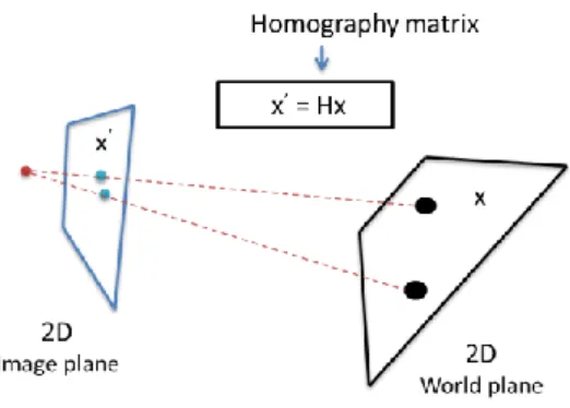
The goal of this research is to accurately estimate the position and orientation of indoor robots. The pose of a ground robot can be expressed by the position (x, y) and the heading angle θ in the global coordinate system. The idea is to fix a laser pointer on the robot vertically pointing to the ceiling, while an external camera is deployed at a fixed position watching the ceiling. The camera is calibrated beforehand using several known-position corresponding points, i.e. pairs of world points and image points. The next step is to search for the laser point projected in the image taken by the camera and then back project the image point to a world point which indicates the position of the robot. A scheme of the system architecture is shown in Fig. 1. Compared with other approaches, the advantages of our system are the following:
There is no accumulation error as in INS, which means the system can work continuously without periodical corrections.
The initial set up of the proposed scheme is simple and the camera just has to be calibrated once with a few corresponding points.
The typical 3×4 projection matrix, which projects 3D world points into 2D image points, is simplified to a 3×3 homography matrix, since we have a projection from the ceiling plane to the image plane, as shown in Fig. 2. This means that we need fewer points for calibrating the camera. It is much easier and faster to find the laser projected point in the image than in other vision-based systems, such as those referred in Section II.
These strong points expand the applications of the proposed system, such as home cleaning robots and home health care robots. Furthermore, the proposed system is a promising solution for a newly developed technology, Visual sensor network (VSN). These networks are composed of smart camera devices and show great potential in tracking, surveillance and monitoring. However, smart camera devices have limited power in their processors. Consequently, a high speed algorithm is necessary.
Depending on the system requirements, this novel concept has several possible system configurations. Here we discuss some of them.
Figure 1. A schematic diagram of the proposed system architecture.
Figure 2. 2D homography.
A. One Laser Dot Pointer and One Camera
B. Two Laser Dot Pointers with Different Colors and One Camera
Through detecting two laser projected points with different colors, such as red and green, two world points are determined. They can be used for estimating the heading angle of a robot or localizing two robots.
C.One Laser Pointer with Certain Pattern and One
Camera
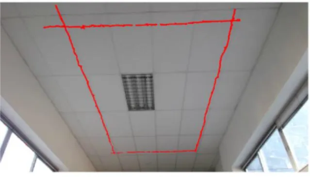
It is possible to convert a simple laser dot into a variety of different patterns with the aid of laser pattern generators. For example, a dotted line or a solid line pattern, as shown in Fig. 3, are able to estimate the position as well as the orientation of a robot, because the direction of the dots or the line relative to the robot is fixed. The procedure of detecting several dots is similar to that of detecting one single dot in the case A. And the detection of a line is an easy and mature task in computer vision. With this configuration, we cannot distinguish whether the robot is looking forward or backward because the laser patterns are symmetric. However, this can be solved by tracking the movement of the robot. Another alternative solution is to complete the orientation information with an additional laser dot pointer to build a certain geometric relation with the existing laser.
Figure 3. Two examples of laser pattern: a dot line pattern and a solid line pattern.
D.Multiple Cameras
Multiple cameras, such as in VSN, can be used to extend the coverage of the system. In this case, a camera switch module should be built to save energy and computational cost. Some recent research on multiple camera selection and deployment can be found in [11] [12].
Considering these possibilities, we can conclude that the proposed system has potential to work in large multi-agent scenarios.
IV. POSE ESTIMATION ALGORITHM
The camera is deployed in a certain place with a good view of the ceiling, which means the working area of the ceiling covers the image as full as possible and moving objects, such as persons, are not seen in the image. The camera is calibrated beforehand manually using several pairs of points with known world coordinates and image coordinates. Once calibrated, the homography matrix is determined and the system starts working. Then it searches for the laser point projected in the image sequences captured by the camera. The position of the robot is easily obtained by a matrix multiplication.
A. Camera Calibration
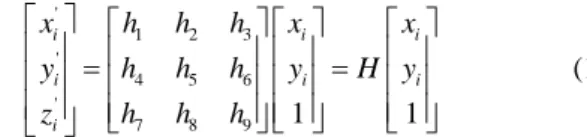
As explained in Section III, the camera calibration in our case consists in the determination of the 3×3 homography matrix. Given a set of points xi in a ceiling plane and a corresponding set of points xi’ in the image plane, 2D homography computes the projective transformation that takes each point xi to xi’ and vice versa which is defined as:
'
1 2 3
'
4 5 6
'
7 8 9 1 1
i i i
i i i
i
x h h h x x
y h h h y H y
z h h h
(1)
where H is the homography matrix and point xi and xi’ are expressed in homogeneous coordinates.
In order to compute the transformation from the image plane to the real world plane, we just need to calculate the inverse of H, namely xi = H − 1x'i. Furthermore, Equation 1 can be re-written as shown in (2).
1 2 3 4 ' ' ' 5 ' ' ' 6 7 8 9
1 0 0 0
0
0 0 0 1
i i i i i i i
i i i i i i i
h h h h
x y x x y x x
h
x y x y y y y
h h h h (2)
The matrix H contains 9 coefficients but it is defined up to scale. Thus the degrees of freedom of H are 8. Each pair of corresponding points leads then to two independent equations. As a consequence, as least four point correspondences have to be specified. Normally we choose more than 4 matching pairs, to gain robustness when there is some error in the measurement. Consequently, the set of equations is over-determined. Then the Direct Linear Transformation (DLT) Algorithm is used to calculate the matrix H [13]. One essential step for DLT is to normalize the data sample. The normalization consists of a translation and scaling of both the world coordinates and the image coordinates: we need to translate the points so that the centroid is centered in the origin and scale the points so that the average distance from the origin is equal to 2. This process can improve the accuracy and provide invariance to different choices of coordinates in the image [13].
B. Laser Projected Point Detection
line detection algorithm is necessary. For example, Hough transformation is an optional solution. After the detection of the laser projected area, we calculate the position and/or orientation through back projecting the image points to world points. An example of the described image processing steps is shown in Fig. 4.
Figure 4. The zoomed laser projected region. a) from the original image. b) from the background subtracted image. c) from the filtered image. d) the
final detection result.
V. EXPERIMENTS
The proposed system is validated in terms of precision and speed. We choose the system proposed in [3] as a reference system for comparison, because it uses a similar technique, which consists in localizing the robot by detecting landmarks from the ceiling.
A. Camera Calibration
In our case, the testing area of the ceiling is about 4 m×6 m and it is composed of 60 cm×120 cm grids. We selected 18 corners of the grids manually from the image (864×480), and we measured their positions in the image and in the real world. To get a better accuracy, we chose the points that filled the image as full as possible (marked with black crosses in Fig. 5). The origin of the coordinate system and the axes are defined as shown in Fig 5. Once we obtained the calibration matrix, we projected the 3D points into the image (marked with red circles in Fig. 5) to check if the calibration result was precise.
B. Accuracy Assessment
It is difficult to give an exact numerical estimation accuracy of our system. Our method to assess the accuracy consists in calculating the 3D positions of several points with known pixel positions. We define the error as the difference between the calculated 3D coordinates and the measured coordinates. Our samples are composed of 36 points with known image coordinates and world coordinates. The mean error in our method is 14 mm in an area of about 24 m2. The accuracy of our proposed system is higher than that of the reference system which is around 10 cm. The result is shown in Fig. 6.
In order to estimate the heading angle, two dots pointers, can be used, as explained in case B. With this configuration, the heading angle accuracy can be estimated with a simple simulation. Let us assume the distance between the two laser points D is 40 cm (according to the actual dimension of our robot Pioneer 3). Let us denote P1 and P2 the ideal positions of the two laser points. As the average position estimation error is 14 mm, we assume that the actual positions of the laser points are uniformly distributed in two circles centered at the ideal positions with radius e = 14 mm. We run a simulation to calculate the angle difference between the estimated line and the ideal line (expressed as θ in Fig. 7). Due to the symmetry, the mean error of the heading angle is zero. The standard deviation is relative to the disparity of the two laser points. The larger disparity they have, the smaller heading angle error they provide. For a disparity of 40 cm, the standard deviation is 2.00 degrees.
Figure 5. The world coordinate system andcamera calibration results: The black crosses are manually selected points for calibration. The red circles are
the back-projected points.
Figure 6. Results of the accuracy assessment experiment. The circles indicate the ground truth and the crosses are the estimated positions of
projected points.
Figure 8. The trajectory of laser points in the image plane.
Figure 9. The trajectory of the laser in the world plane (the definition of the coordinate system is the same as in Fig. 5).
C. Computational Cost
To illustrate the real-time character of the proposed method, we implemented an experiment with a red laser pointer pointing to the ceiling and we made the robot move on the floor around a rectangle of 2.4 m×4.4 m. The processing of the images was done following the steps explained in Section IV. The detected laser points are shown in Fig. 8. Fig. 9 shows the trajectory of the laser in the world coordinate system. We can see from these two figures that the trajectory in the world coordinate system coincides with the trajectory in the image plane. We processed the off-line video of 8558 frames (15 frames/s, 864×480), and the average time for processing one frame is 26 ms, which means the data update rate can achieve about 27 Hz. This processing time is shorter than that of the reference system, which is 159 ms. On one side, the high processing speed largely decreases the computational cost. On the other side, it decreases the limitation of the robot moving speed, since the latency caused by localizing robots is low.
VI. CONCLUSIONS AND DISCUSSIONS
In this paper, we have proposed a new low-cost, accurate and fast approach for robot indoor localization with a fixed camera and a laser pointer mounted vertically on the robot. In the experimental test, the mean position estimation error is 14 mm and the algorithm runs at about 27 Hz, which means that it meets the high speed and precision requirements of indoor ground robot pose estimation. It is a promising solution for a variety of applications, such as home automation for taking
care of daily life of the elderly and the disabled due to its low cost and ease of use.
This paper is focused on proposing a new approach and validating its accuracy and speed. But much further work can be done based on this concept. For example, we are planning to implement a filter to smooth the estimation results and also predict the position when the laser projected point falls into the holes of the air conditionings or in other situations where the point disappears from the image.
REFERENCES
[1] Barshan, Billur, and Hugh F. Durrant-Whyte. "Inertial navigation systems for mobile robots." Robotics and Automation, IEEE Transactions on 11.3, pp. 328-342, 1995.
[2] Se, Stephen, David Lowe, and Jim Little. "Vision-based mobile robot localization and mapping using scale-invariant features." Robotics and Automation, 2001. Proceedings 2001 ICRA. IEEE International Conference on. Vol. 2. IEEE, pp. 2051-2058, 2001.
[3] Hwang, Seo-Yeon, and Jae-Bok Song. "Monocular vision-based SLAM in indoor environment using corner, lamp, and door features from upward-looking camera." Industrial Electronics, IEEE Transactions on 58.10, pp. 4804-4812, 2011.
[4] Lin, Guoyu, and Xu Chen. "A robot indoor position and orientation method based on 2D barcode landmark." Journal of Computers 6.6, pp. 1191-1197, 2011
[5] Fiala, Mark , Vision guided control of multiple robots, in Proceeding of the first Canadian conference on computer and robot vision, IEEE, pp. 241-246, 2004
[6] Kang, Yeonsik, et al. "A lidar-based decision-making method for road boundary detection using multiple kalman filters." Industrial Electronics, IEEE Transactions on 59.11, pp. 4360-4368, 2012. [7] Jung, Myung-Jin, et al. "Structured light 2D range finder for
simultaneous localization and map-building (SLAM) in home environments." Micro-Nanomechatronics and Human Science, 2004 and The Fourth Symposium Micro-Nanomechatronics for Information-Based Society, 2004. Proceedings of the 2004 International Symposium on. IEEE, pp. 371-376, 2004.
[8] DiGiampaolo, Emidio, and Francesco Martinelli. "Mobile robot localization using the phase of passive UHF RFID signals." Industrial Electronics, IEEE Transactions on 61.1, pp. 365-376, 2014. [9] Raghavan, Aswin N., et al. "Accurate mobile robot localization in
indoor environments using bluetooth." Robotics and Automation (ICRA), 2010 IEEE International Conference on. IEEE, pp. 4391-4396, 2010.
[10] Biswas, Joydeep, and Manuela Veloso. "Wifi localization and navigation for autonomous indoor mobile robots." Robotics and Automation (ICRA), 2010 IEEE International Conference on. IEEE, pp. 4379-4384, 2010.
[11] Soro, Stanislava, and Wendi Heinzelman. "Camera selection in visual sensor networks." Advanced Video and Signal Based Surveillance, 2007. AVSS 2007. IEEE Conference on. IEEE, pp. 81-86, 2007. [12] Park, Johnny, Priya C. Bhat, and Avinash C. Kak. "A look-up table
based approach for solving the camera selection problem in large camera networks."Proceedings of the International Workshop on Distributed Smart Cameras (DCS’06), pp.72-76, vol. 31, 2006. [13] Hartley, Richard, and Andrew Zisserman. Multiple view geometry in
computer vision. Vol. 2. Cambridge, 2000, pp.88-110.
Juan Li was born in Shandong, China in 1988. In 2010, she received the BS degree in electrical engineering from Beihang University, China. From September 2011, she started the Ph.D study in Department of Signals, Systems and Radio communications in Universidad Politécnica de Madrid. Focus of her research is on indoor localization methods and applications based on data fusion from different sources, including computer vision and motion sensors.
Paula Tarrío obtained her M.S. and Ph.D. degrees in telecommunication engineering from the Universidad Politécnica de Madrid, Spain, in 2003 and 2011, respectively, and her M.S. in physics from the Universidad Complutense de Madrid, Spain, in 2013.
From 2011 to 2014 she was a post-doctoral researcher with the Data Processing and Simulation Group at the Universidad Politécnica de Madrid and she is currently a post-doctoral researcher with the Service d’Astrophysique at CEA-Saclay, France.
Her research interests include localization and tracking techniques, wireless sensor networks, sensor-based gesture recognition, image processing and astrophysical image processing.
Hamid Aghajan received his BS degree in 1989 from
Sharif University of Technology, Tehran, Iran, and his MS and PhD degrees from Stanford University in 1991 and 1995, respectively, all in Electrical Engineering. He is with the Department of Telecommunication and Informatics (TELIN) in Gent University, and has also been director of the Ambient Intelligence Research (AIR) Lab at Stanford University. Focus of research in his group is on methods and applications of Ambient Intelligence with an emphasis on behaviour modelling based on activity monitoring with multi-camera networks. Recent work includes using a network of motion sensors to develop a long-term behaviour model indicating the wellness of the user and tracking changes which may result from physical or cognitive issues.
Prof. Aghajan is Editor-in-Chief of "Journal of Ambient Intelligence and Smart Environments", and has served as guest editor for IJCV, IEEE Trans. on Multimedia, CVIU, and IEEE J-STSP. He was general chair of ACM/IEEE ICDSC 2008, AMI 2011, ICMI 2012, and program chair of ICDSC 2007. He has organized workshops, special sessions, or tutorials at ECCV, ACM MM, CVPR, ICCV, ICMI, FG, ECAI, EI, and ICASSP.
Wilfried Philips was born in Aalst, Belgium on
October 19, 1966. In 1989, he received the Diploma degree in electrical engineering and in 1993 the Ph.D degree in applied sciences, both from Ghent University, Belgium. From October 1989 until October 1997 he worked at the Department of Electronics and Information Systems of Ghent University for the Flemish Fund for Scientific Research (FWO-Vlaanderen), first as a research assistant and later as a post-doctoral research fellow.
Since November 1997 he is with the Department of Telecommunications and Information Processing of Ghent University, where he is currently a full-time professor and is heading the research group ``Image Processing and Interpretation',' which is also part of the Flemish ICT research institute iMinds. He is also a senior member of IEEE.
Some of the recent research activities in the group include image and video restoration and analysis, image and video quality assessment and image analysis and computer vision. Important application areas targeted by the group include surveillance, industrial inspection, HD video improvement.
José R. Casar graduated in Telecommunication
Engineering in 1981 and gained a Ph.D. degree in 1983 from Department of Signals, Systems and Radio communications of Universidad Politécnica de Madrid (UPM).
During 1993 he was the Vice-Dean for Studies and Research at the Telecommunications School (UPM). During 1995 he was Deputy Vicepresident for Research of the UPM, from 1996 to February 2000 Vicepresident for Research at the same University and Adjunct to the Rector for Strategic Programs from February 2000 to June 2004. At the present time he is Head of the Data Processing and Smart Spaces Group at UPM.