T
An Adjustable Compliant Joint for Lower-Limb Exoskeletons
Manuel Cestari, Daniel Sanz-Merodio, Juan Carlos Arevalo, and Elena Garcia
Abstract—The field of exoskeletons and wearable devices for
walking assistance and rehabilitation has advanced considerably over the past few years. Currently, commercial devices contain joints with stiff actuators that cannot adapt to unpredictable en- vironments. These actuators consume more energy and may not be appropriate for human–machine interactions. Thus, adjustable compliant actuators are being cautiously incorporated into new ex- oskeletons and active orthoses. Some simulation-based studies have evaluated the benefits of incorporating compliant joints into such devices. Another reason that compliant actuators are desirable is that spasticity and spasmodic movements are common among pa- tients with motor deficiencies; compliant actuators could efficiently absorb these perturbations and improve joint control. In this paper, we provide an overview of the requirements that must be fulfilled by these actuators while evaluating the behavior of leg joints in the locomotion cycle. A brief review of existing compliant actuators is conducted, and our proposed variable stiffness actuator prototype is presented and evaluated. The actuator prototype is implemented in an exoskeleton knee joint operated by a state machine that ex- ploits the dynamics of the leg, resulting in a reduction in actuation energy demand and better adaptability to disturbances.
Index Terms—Active orthoses, compliant joint, force sensor.
I. INTRODUCTION
HE last few years have seen a considerable increase in the implementation of devices, such as exoskeletons and ac-tive orthoses, that help people with walking disabilities to regain strength in their legs and joints so they can stand or even walk again. The effort to restore mobility to the legs of these patients has encouraged the development of many devices, such as Re- Walk (Argo Medical Technologies) [1], Ekso (Ekso Bionics) [2], REX (REX Bionics) [3], and our current prototype ATLAS (CAR) [4]. These devices use electric motors that require a large gear reduction to achieve the desired torque for exoskeleton joints while maintaining a small size. However, when physical interaction with the world is required while maintaining inter- action with the user, particularly interaction that involves an impact or kinetic energy transfer [5], the traditional approach of using stiff actuators from classical robotic applications to hold precise positions [6] is not ideal.
One near future goal of powered wearable devices is to be incorporated into the everyday life activities of the user. Hu- mans are capable of autonomously producing a wide range of stable movements in environments with unpredictable distur- bances. Dynamic control of joint stiffness is crucial for humans to adapt to changes in environmental conditions [7]. Modulation of joint stiffness can achieve a significant reduction in energy expenditure and transmitted force [8]. Some research groups working on topics related to walking and leg rehabilitation are proposing joint prototypes whose mechanical configuration al- lows the device’s stiffness to be varied while controlling the position of the joint according to the gait, the user’s needs, or environmental requirements. However, the current state of the art in the field of compliant joints was not designed for portable lower-limb exoskeletons, and they do not meet all of the require- ments of this application. This paper presents a variable stiffness actuator, conceived as an adjustable compliance knee joint for exoskeletons that incorporates characteristics for achieving en- ergy efficient locomotion and torque sensing without extra bulky components.
In this paper, an overview of the biomechanics of locomotion is presented in Section II. The technical requirements and spec- ifications of exoskeleton joints and a brief comparison among the existing joint actuators are given in Section III. Finally, the ARES actuator prototype and its operating principle are de- scribed in Section IV, and the evaluation of this prototype in the ATLAS exoskeleton is presented and discussed in Section V. Section VI provides some conclusions.
II. BIOMECHANICS OF LOCOMOTION
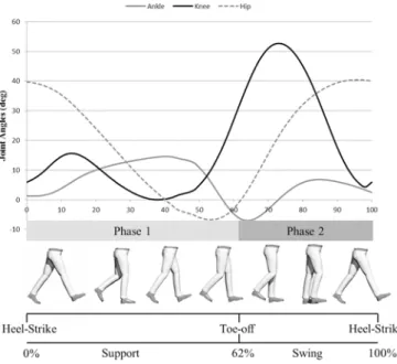
It is particularly useful to know the requirements of each joint because the power, velocity, and function (e.g., power genera- tion, energy dissipation) of each joint vary dramatically along every phase of the locomotion cycle. In Fig. 1, a clinical gait analysis (CGA) pattern is presented at the top, illustrating the angular variation in the sagittal plane of the joints of the leg. The locomotion cycle (at the bottom of Fig. 1) is divided into two main phases: one starts with the heel-strike and ends with the toe-off, and the other covers the swing of that leg. An economic gait-control analysis is performed based on a prior publication that analyzed the dynamic principles of the human gait [9]. The physical requirements that a knee joint should fulfill in the locomotion cycle are presented in the following sections.
A. Compliant Joint
Fig. 1. CGA and locomotion cycle phases (right leg).
almost constant during the support phase. In the CGA, a small change in the knee angle is observed (0–38% of the stride), corresponding to the adaptation of the leg to the ground, or the load response. By taking advantage of the joint compliance, during the stance phase, the knee behaves like a spring with a suitable stiffness that allows a proper load response and a good adaptation to the irregularities in the terrain.
B. Stiff Joint
At the end of the support phase, during the toe-off, the leading leg gives the impulse to the body to achieve the redirection of the center of mass of the body[9]. The joint at the knee must increase its stiffness to assure the maximum transference of the power generated by the ankle at the push-off. This impulse occurs in a very small instant.
C. Free Joint
During the swing phase, the leg transitions from a flexed knee in the toe-off to a fully extended knee prior to the heel-strike. This knee motion is achieved by utilizing the hip movement and leg inertia. By reducing the stiffness at the knee to a minimum, the kinetic and potential energy can be used to extend the knee without generating significant power at the joint.
III. TECHNICALREQUIREMENTS ANDSPECIFICATIONS
OFCOMPLIANTJOINTS FOREXOSKELETONS
Many existing joint actuators incorporate compliance in their mechanisms. Adding springs to the mechanical structure of tra-ditional actuators has been shown to significantly improve their performance in meeting the requirements of joint exoskeleton applications.
Some of the many advantages of the new actuators are the following:
1) achieving stable behavior during hard contact; 2) protecting the joints from impact and shocks; 3) the possibility of storing elastic energy.
Early implementations of physically compliant actuators can be observed in some of the robotic legs of the MIT Leg Labora-tory[10]. They have also been applied to exoskeleton joints in the IHMC Mobility Assist Exoskeleton[11]and in the LOPES rehabilitation device[12]. An elastic element is placed in series with the actuator device in the mechanism, giving some of the compliant properties. By adding elastic elements, it is possible to utilize the deflection that occurs when a torque/force is ap-plied for torque/force sensing. One of the disadvantages of the traditional series elastic actuators (SEAs) is that the compliance is predetermined; thus, the actuator is limited to a specific appli-cation and user size. Novel adaptations from the SEA concept have been developed recently, improving the performance and force bandwidth of traditional SEAs in compact designs, such as the compact SEA[13], the high-Performance SEA[14], and cRSEA[15].
Research has shown that a reduction of energy consumption is achieved by utilizing the elasticity in the actuator system. In a simulation-based work[16], series elastic and parallel elastic actuators are evaluated based on the reduction in peak energy de-mands, with the conclusion that the series elastic design reduces the peak considerably for exoskeleton applications.
The effects of user weight and walking on varying terrain de-mand different actuator stiffness. Similarly, dynamic control of the stiffness is crucial in humans to adapt to changes in the envi-ronment or to the requirements of the tasks performed[7]. Novel designs incorporate the ability to physically change the stiffness of the mechanism. The recent European project VIACTORS [17]stance as a proof of this, where the concept of variable impedance actuation is used to tackle their goal of development, exploitation, and integration of variable impedance actuator sys-tems in manipulation, locomotion, and rehabilitation.
Some of the capabilities and characteristics that are useful to evaluate in novel actuators that exploit the natural dynamics of the leg during gait are presented in the following sections.
A. Size and Dimensions
The user that will wear the device should be able to handle it and will be more satisfied if it has an aesthetically pleasing appearance. Therefore, small size and reduced weight are re-quired for exoskeleton applications. The size reduction avoids the problem of bothering the regular activities of the user (such as sitting or passing through a door), and by having lower di-mensions, the associated inertia that the actuators must resist decreases. The series arrangement along the longitudinal axis of the leg segments is preferred to parallel configurations to avoid excessive length in the joint system along the lateral side and achieve smaller dimensions.
TABLE I
COMPARISON OFPHYSICALVARIABLE-STIFFNESSACTUATORS AND THEDESIREDSPECIFICATIONS FORLOWER-LIMBEXOSKELETONS
B. Stiffness Range
The range of stiffness is the ability of the actuator to go from very stiff to minimally stiff in the mechanism, thus adjusting the mechanical impedance in the device as desired in a powered orthosis. Joint stiffness should vary depending on the ground stiffness, gait speed, and terrain irregularities among other fac-tors. By analyzing the behavior of the joints during locomotion, three main desirable states of stiffness were identified:
1) Medium stiffness for the purpose of adaptation at the
heel-strike: A tradeoff between joint and ground stiffness
de-termines the value that should be adopted by the joint. Walking speed, user weight, and ground irregularities also affect the determination of this value, which is why the value is not fixed and the ability for adjustment is desired in a compliant actuator. In the CGA knee pattern shown in Fig. 1, a bump at the beginning of the support phase is observed (the curve inside the dotted circle); this reaction at the knee is due to the load response when the heel-strike occurs. The knee should adapt to this 6–10°of deflection while providing a torque of up to 20 N·m[18].
2) High stiffness (or nearly rigid) for giving the impulse
during the toe-off phase: For a child weighing 35 kg with
a peak torque of approximately 40 N·m, 2300 N·m/rad should be sufficient to provide the required impulse (the equivalent of 40 N·m for 1°of deflection).
3) Minimum stiffness for the swing phase: During the swing, the knee is almost free, utilizing the potential and ki-netic energy when the hip extends (approximately zero stiffness) and achieves full extension without the need of positive power in the joint[18].
C. Embedded Force Sensor
It is possible to adapt to changes in environmental condi-tions by force-controlling the joint. Robots and actuated systems must be able to sense and control forces in addition to knowing where they are in their work space, particularly in the pres-ence of human–machine interaction. The force sensor should be embedded in the mechanism to maintain a reduced size and dimension, instead of been an extra element in the mechanism. The range of torque at the knee joint goes from approximately
−30 to 60 N·m in a 70-kg adult at a walking speed of 1.6 m/s and from−17 to 40 N·m for a child of approximately 35 kg at the same speed. The force sensor must be functional at these ranges, particularly during the swing phase, to utilize the po-tential and kinetic energy by incorporating a zero-force control. The sensor must detect small torques to avoid additional energy losses in the motors when the zero-force control is achieved by controlling the force at the joint.
D. Stiffness Adjustment Speed
High speed is required in the stiffness adjustment to utilize the elasticity and leg dynamics. The energy stored in the elastic elements is released when the opposing force disappears at the speed of recovery of the elastic element (typically high). Thus, a rapid stiffness adjustment is required to utilize this released energy.
stiffness adjustment. The stiffness adjustment by compressing the elastic element requires sufficient power to overcome the opposite spring force, whereas the pivot point principle[19] ap-pears optimal for stiffness regulation because the second motor does not have to overcome the elastic element opposite force due to the operational principle of precompression.
Table I compares current joint developments using physical variable stiffness actuators [7], [20]–[25], focusing on some of the main characteristics and principles through which the variable stiffness and damping are achieved[26]. These values are compared with the desired specifications for lower-limb ex-oskeletons. Many of the presented joints display very good prop-erties for exoskeleton applications; however, the future evolution of these designs should focus on the size and weight reduction from this application perspective. Some of the designs presented in Table I were conceived to be used in a specific joint. Knee and shoulder joints integrate some of the same key elements with different torque requirements. Considering the previous four technical specifications that these authors highlight as part of the key elements for exploiting natural dynamics in Section II, the designs of the VS-Joint and QA-Joint from the German Aerospace Center (DLR) and those from the Italian Institute of Technology (IIT) appear to collect most of the desired features in terms of stiffness range and adjustment speed (expressed in Table I). The size of these designs is considered excessive for wearable devices. Although compact, the parallel arrangement of the components results in a bulky joint. The AwAS-II, along with many of the designs from the IIT[19],[27], presents fea-tures that we consider very useful for exoskeleton applications, but the size is still excessive for our requirements and the torque sensing is achieved by an additional element in parallel with the actuation system, which increases the lateral size. However, the stiffness adjustment technique exceeds, energetically speaking, the adjustment capability of directly compressing the elastic el-ements and would be an important feature to incorporate in an actuator for lower-limb exoskeleton requirements.
IV. ACTUATORWITHADJUSTABLE-RIGIDITY ANDEMBEDDED
SENSOR(ARES) PROTOTYPE
An ARES has been conceived as a knee joint to cover the requirements of the ATLAS active orthosis knee joint. Because the ATLAS orthosis is intended to be worn by children, rotary actuators were chosen instead of linear actuators to consider the wide range of sizes of potential users. Linear actuators impose limits on the link length adjustment.
A. Actuator Design
Fig. 2 presents a CAD view of the proposed joint, where the components of the actuator are arranged along the structure to reduce lateral volume. The joint can be divided into two main components: a stiff set and compliant mechanism.
B. Stiff Set
The stiff set is a conventional combination of a stiff actua-tor and gearbox. A flat Maxon 90-W brushless DC moactua-tor in
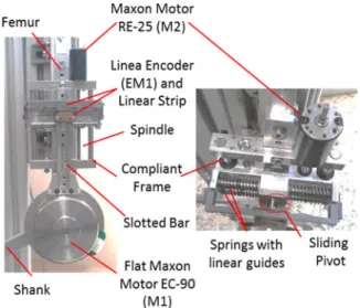
Fig. 2. Actuator prototype main components.
Fig. 3. Coupling between the actuator components.
combination with a Harmonic Drive unit with a 100:1 reduction ratio was selected to achieve the required large torque/size and torque/weight ratios during the locomotion cycle. The combi-nation of the motor M1 and Harmonic Drive control the equi-librium position of the joint. These two elements and the slotted bar comprise the stiff set.
C. Compliant Mechanism
The compliant mechanism is responsible for the joint com-pliance and its adjustment. A set of elastic elements is placed in a slider system that is connected to a spindle drive for adjusting the slider position along the compliant frame. A 20-W Maxon DC motor, RE-25, is connected to the spindle drive to exert the required force for varying the slider position on command. The linear guides along the frame are conceived to reduce the external forces transmitted to the spindle.
along the slotted bar (see Fig. 3). This configuration provides no additional length in the lateral plane.
The compliant knee joint is based on the pivot displacement principle; according to the work of the VIACTORS consortium [26], it can be further classified as a controllable transmission ra-tio with stiffness adjusted by lever length. This configurara-tion, in which the actuator position and stiffness control are decoupled, achieves higher energy efficiency[28], as have been remarked in many of the designs from the IIT, such as the AWAS-II, the vsaUT-II[29]and other based on the same working principle.
When a torque is exerted in the stiff set, the force is transmitted along the slotted bar; the compliant mechanism will resist this force to achieve a rotation in the joint. The compliance of the joint is closely related to the embedded force sensor and is one of the novel concepts implemented in this compliant joint. The weight and size are reduced by utilizing the elastic elements and mechanical configuration of the system to both regulate the physical impedance and measure the force. The reduced weight and size are an advantage when compared with other compliant joints that employ different elements in parallel to present similar characteristics.
D. Embedded Force Sensor
When the slotted bar transmits a force produced by a torque exerted by the stiff set or by an external disturbance, the sliding pivot attached to the elastic mechanism suffers a displacement due to the compression of the springs on this element. The sliding pivot will vary its distance from the joint axis slightly as the spring compression occurs (see Fig. 4). The displacement of the sliding pivot is constrained by linear guides to avoid bending of the elastic elements, as shown in Fig. 3. Because the elastic elements do not bend and the contact between the slotted bar and sliding pivot is not blocked during joint deflection, the torque measure is directly related to the displacement of the elastic element by the following relationship:
τ =2·ΔX·Kequiv·Lf(∅)
cos (∅) (1)
where ΔX corresponds to the elastic elements compression measured by an encoder;Kequiv is the equivalent rigidity of
the elastic elements, depending on the arrangement; ∅ is the deflection angle between the actuator and joint, a function of the displacement (ΔX) of the sliding pivot and the distance to the joint axis (Lf(∅)).
The arm length,Lf(∅), will slightly vary with the increase of
the deflection due to the mechanism to avoid bending the elastic elements.
To adjust the system compliance, the sliding pivot can be displaced along the slotted bar by modifying the position of the elastic mechanism in the compliance frame by ac-tion of the actuator M2. The adjustment of the pivot posiac-tion changes the distance to the joint axis, increasing or decreasing the arm length and thus varying the force exerted by the slotted bar at a fixed torque. This process ultimately changes the overall joint stiffness.
Fig. 4. Embedded-force sensor mechanism.
E. Joint Prototype
The actuator prototype was built to improve the contact point (the pivot with the slotted bar), to improve the linear guide’s dis-placements, and to exploit the maximum compression allowable by the springs in the elastic mechanism for a wide range of force measurement. In Fig. 5, the actuator is shown incorporated into a test joint. Most parts of the prototype are made of aluminum to reduce weight. The encoder and linear strip housings were made with a 3-D printer, as no resistance is need in those elements. The testbed is based on two bars that resemble the femur and tibia and are connected in a pivot point that resembles the knee joint.
Fig. 5. Joint testbed with ARES.
TABLE II
GENERALSPECIFICATIONS OF THEVARIABLEIMPEDANCEACTUATOR
Compliant Joint Properties Peak Torque Up to 76 N·m Max Deflection ±8°
Stiffness Adjusting Time 0.6 s Weight 900 g Length 235 mm Width 50 mm Power 90 W
Fig. 6. Experimental setup diagram.
V. EXPERIMENTALSETUP ANDEVALUATION
To evaluate the torque sensing capability of the ARES proto-type, the system was incorporated to a joint testbed composed of two pivoting segments that resemble the knee joint, as de-scribed above. A diagram of the experimental setup is shown in Fig. 6. An external extensional spring attached to the shank at a known distance (Lextof 170 mm) from the joint axis allows us
to emulate a variable load at the joint. The extensional spring
Fig. 7. Open-loop torque tracking at high stiffness (Lf(∅)= 170 mm).
Fig. 8. Open-loop torque tracking at low stiffness (Lf(∅) = 96 mm).
force is used as reference to match the torque measured by the embedded sensor in the actuator.
The M1 motor from the stiff set was commanded to rotate following different inputs, ramps, and steps to evaluate the per-formance of the embedded force sensor mechanism. Because the joint position varies in response to these inputs, the exten-sion spring is elongated and a torque is exerted at the joint. A rotary magnetic encoder placed at the knee measured the real joint rotation, and the torque reference is calculated based on the knowledge of the geometric configuration in the experimental setup.
A. Torque Sensing Evaluation
To test the force sensor’s capabilities, different arm lengths (Lf(∅)) were evaluated and a wide range of inputs were
com-manded. Ramp inputs commanded in Figs. 7 and 8 were set at 25, 10, 5, and 2.5 Hz to determine if the response of the elastic elements presented significant variations or delay. The spring arrangement of the embedded sensor was set to an equivalent rigidity (Kequiv) of 17 N/mm. In Figs. 7 and 8, open-loop torque
Fig. 9. Joint angle relationship.
measured signal that does not represent complications for our application.
For a given spring compression of the embedded sensor, the torque range is higher at high stiffnesses than at low stiffness, as expected. Similarly, the transmitted force is smaller at high stiffnesses; the spring’s compression is minimum, and less pre-cision is expected than at low stiffnesses, where the transmitted force and spring compression is higher.
For our actuator, the impedance variation is achieved mechan-ically by tuning the equivalent stiffness of the compliant system; traditional evaluations of embedded sensors are completed us-ing Bode diagrams to evaluate the bandwidth of the associated elastic elements. By adjusting the sliding pivot position along the compliance frame, the frequency response and the natural frequency of our system can be modified to avoid bandwidth saturation. The Bode diagram is not plausible because there is a different Bode diagram for each equivalent stiffness value, leading to an infinite number of Bode diagrams in our range of operation.
The compliant joint is a mechanism integrated by the stiff set and compliant mechanism. The stiff M1 motor in combination with the deflectionφdue to spring compression in the presence of an external force or exerted torque determines the real joint position. Fig. 9 shows the joint angles when a set of inputs, ramps, and consecutive steps were commanded to the M1 motor. The Hall sensor of the M1 motor gives the commanded angle (q); the rotary magnetic sensor at the knee allows us to know the joint angular variation (β), and the spring’s compression at the elastic mechanism for a known arm length provides us with the angular deflection (φ) due to the exerted torques.
As the system is coupled through the sliding pivot and the slotted bar, it is evident that the angle variations at the joint, motor, and deflectionφare strictly related
β =q−φ (2)
whereβcorresponds to the joint angle between bodies 1 and 2, measured with a rotary encoder at the knee;qis the M1 motor angle at the HD output, given by the Hall sensor; andφis the deflection angle between the actuator and joint, a function of
Fig. 10. Simplified control diagram.
Fig. 11. Actuator prototype implementation in the ATLAS’s knee.
the spring compression and the distance of the sliding pivot to the joint axis.
When no torque is applied,βandqare equal because no load is applied, as observed before the ramp inputs in Fig. 9. Because a deflection occurs due to the elongation of the extension spring, φincreases as a function of the spring’s compression and the commanded position to M1 differs from the joint position. Sim-ilarly, when step inputs are commanded, the extension springs resist the joint movement more quickly and no appreciable re-gion without acting torque can be observed.
B. Exoskeleton Knee-Joint Implementation
Fig. 12. Modified CGA for the knee state machine.
A velocity control is implemented to follow the modified CGA pattern while a state machine gain-scheduled control is performed to modify rigidity. The measure of the force encoder, of the joint position and calculations are made by de FPGA, inside the Compact RIO, spending only 3 ms by loop, allow-ing accurate monitorallow-ing of each control stage. Communication between every motor controller is achieved by an industrial CAN-OPEN bus which is fast enough for our purposes.
The motion control of active orthoses has traditionally been based on the rigid tracking of CGA reference patterns, typically resulting in high power consumption. The position pattern ob-tained from the CGA incorporates the intrinsic compliance of the human joints.
Therefore, to utilize the compliance of the actuator and leg dynamics, instead of following the CGA pattern accurately, a state machine is incorporated as follows (presented in Fig. 12).
1) Phase 1: In the support phase, the knee motor is blocked. The compliance of the joint must provide the ground adap-tation and load response at the heel-strike.
2) Phase 2: At toe-off, the actuator provides impulse; the elastic elements are compressed, storing energy. In this first test, a fixed stiffness was set to ensure the first two stages could operate correctly in the test scenario. 3) Phase 3: During the swing phase, a zero-force control
was implemented because our actuator cannot achieve zero stiffness in this version. The storage energy during the toe-off and the hip motion helps the control to achieve full extension of the knee with a low energy requirement. The results obtained in terms of joint motion and current consumption of the actuator to achieve the commanded gait are presented and contrasted with the results when working with traditional stiff actuators in the following figures.
In Fig. 13, the commanded position in the actuator controlled by the state machine during three gait cycles is presented; in this figure, there is a slight bump at the knee joint angle when the commanded position in the actuator is constant. The compliance in the joint allows the knee to adapt to the ground during the support phase, without the need of command and the resulting wasted energy. This behavior resembles the one observed in the CGA pattern of the knee that is conventionally obtained by stiff trajectory tracking of conventional actuators. The locking in the
Fig. 13. Knee angle comparison. Traditional stiff actuators versus compliant actuator controlled by a state machine.
Fig. 14. Current consumption with stiff actuators versus the compliant joint.
knee can be commanded by taking advantage of the reduction of the gearbox in the actuator system (the Motor-HD set) and the settled compliance, allowing a considerable amount of energy savings in comparison with traditional actuators, as observed in Fig. 14. Tests were performed with the use of an external power supply with almost constant voltage; for this, Fig. 14 illustrates clearly the energy savings when comparing stiff actuator against ARES actuator with a control strategy that exploits the dynamics of the leg and the actuator characteristics.
The smallest current peaks in the compliant actuator are most likely due to the presence of elastic elements such that when a change of direction in the rotation occurs, the compressed springs contribute to movement, reducing the energy required from that of traditional stiff actuators. Implementing an energy-economic gait and exploiting the compliant actuator’s charac-teristics at the knee joint achieve a 39% reduction of energy expenditure compared with traditional stiff actuation.
VI. CONCLUSION
Natural adaptation of the knee joint during normal human walking is a requirement that must be met by active lower-limb orthoses and exoskeletons. Moreover, a considerable number of potential users of active orthoses suffer spasmodic movements and non-uniform joint rigidity, making intrinsic compliance in their joints absolutely necessary. Among the design require-ments, active orthosis actuators must occupy a small space and must be lightweight to be comfortable, aesthetically pleasing, and portable. Therefore, this study presents the ARES joint actu-ator prototype that features many of the characteristics required for an active orthosis: intrinsic compliance to allow human– machine interaction, small size, light weight, and force control capability. ARES is conceived as an actuator to be use in ex-oskeletons for kids; thus, its lateral size is a determinant factor when compared with any other exoskeleton currently available. This compliant actuator has been designed taking into consider-ation not just the joint requirements but also the different control strategies that can be implemented into the control of the ex-oskeleton joint, in order to achieve energy savings, is designed to be force-controlled and to utilize the different elements included in it to achieve different tasks, such as the compliant behavior due to the elastic elements and their utilization for achieving a good torque measure. The arrangement of the elements allows for a reduced lateral size.
The adjustable rigidity is closely related to the torque mea-surement scale. By proper adjustment, the actuator can be con-trolled for different functions, such as rehabilitation or walking at different speeds. The results obtained during trials suggest that adjusting the rigidity during operation would allow us to implement different control strategies to better exploit the gait dynamics. A controller was implemented based on an evaluation and characterization of the joint motion during a gait utilizing the properties of the actuator. A reduction in the energy con-sumption was noted during tests, reaching 39% when compared with stiff actuation. This reduction was achieved using the com-pliance in the joint and the inherent stiffness of the harmonic drive reductions.
REFERENCES
[1] A. M. T. Ltd. (2013).[Online]. Available: http://www.argomedtec.com/ [2] E. Bionics. (2013).[Online]. Available: http://www.eksobionics.com/ [3] R. Bionics. (2013).[Online]. Available: http://www.rexbionics.com/
[4] E. Garcia, D. Sanz-Merodio, F. Sanchez, J. Arevalo, and
P. Gonzalez-de-Santos, “Development of the atlas lower-limb active ortho-sis,” in Proc. Int. Conf. Climbing Walking Robots (suppl.), 2011, pp. 23–32. [5] J. Hurst and A. Rizzi, “Series compliance for an efficient running gait,”
IEEE Robot. Autom. Mag., vol. 15, no. 3, pp. 42–51, Sep. 2008.
[6] R. Ham, T. Sugar, B. Vanderborght, K. Hollander, and D. Lefeber, “Compliant actuator designs,” IEEE Robot. Autom. Mag., vol. 16, no. 3, pp. 81–94, Sep. 2009.
[7] S. Migliore, E. Brown, and S. DeWeerth, “Biologically inspired joint stiffness control,” in Proc. IEEE Int. Conf. Robot. Autom. , 2005, vol. 1–4, pp. 4508–4513.
[8] C. English and D. Russell. (1999). Mechanics and stiffness lim-itations of a variable stiffness actuator for use in prosthetic limbs. Mech. Mach. Theory. [Online]. 34(1), pp. 7–25. Available: http://www.sciencedirect.com/science/article/pii/S0094114×98000263
[9] D. Sanz-Merodio, M. Cestari, J. C. Arevalo, and E. Garcia, “Control motion approach of a lower limb orthosis to reduce energy consumption,”
Int. J. Adv. Robot. Syst., vol. 9, 2012. DOI: 10.5772/51903.
[10] D. Robinson, J. Pratt, D. Paluska, and G. Pratt, “Series elastic actuator development for a biomimetic walking robot,” in Proc. IEEE/ASME Int.
Conf. Adv. Intell. Mechatron., 1999, pp. 561–568.
[11] H. K. Kwa, J. Noorden, M. Missel, T. Craig, J. Pratt, and P. Neuhaus, “Development of the IHMC mobility assist exoskeleton,” in Proc. IEEE
Int. Conf. Robot. Autom., 2009, pp. 2556–2562.
[12] H. Vallery, J. Veneman, E. Van Asseldonk, R. Ekkelenkamp, M. Buss, and H. Van Der Kooij, “Compliant actuation of rehabilitation robots,” IEEE
Robot. Autom. Mag., vol. 15, no. 3, pp. 60–69, Sep. 2008.
[13] S. M. M. Rahman and R. Ikeura. (2012). A novel variable impedance compact compliant ankle robot for overground gait rehabilitation and assistance. Procedia Eng. [Online]. 41, pp. 522–531. Available: http://www.sciencedirect.com/science/article/pii/S1877705812026070 [14] N. Paine, S. Oh, and L. Sentis, “Design and control considerations for
high-performance series elastic actuators,” IEEE/ASME Trans. Mechatronics, vol. 19, no. 3, pp. 1080–1091, Jun. 2014.
[15] K. Kong, J. Bae, and M. Tomizuka, “A compact rotary series elastic actuator for human assistive systems,” IEEE/ASME Trans. Mechatronics, vol. 17, no. 2, pp. 288–297, Apr. 2012.
[16] S. Wang, W. Van Dijk, and H. Van Der Kooij, “Spring uses in exoskeleton actuation design,” in Proc. IEEE Int. Conf. Rehabil. Robot., Jun. 29/Jul. 1, 2011, pp. 1–6.
[17] VIACTORS. (2013).[Online]. Available: http://www.viactors.org [18] G. Stoquart, C. Detrembleur, and T. Lejeune, “Effect of speed on
kine-matic, kinetic, electromyographic and energetic reference values during treadmill walking,” Neurophys. Clinique, vol. 38, pp. 105–116, 2008. [19] A. Jafari, N. Tsagarakis, and D. Caldwell, “A novel intrinsically energy
efficient actuator with adjustable stiffness (AwAS),” IEEE/ASME Trans.
Mechatronics, vol. 18, no. 1, pp. 355–365, Feb. 2013.
[20] B. Vanderborght, N. Tsagarakis, C. Semini, R. Van Ham, and D. Caldwell, “MACCEPA 2.0: Adjustable compliant actuator with stiffening character-istic for energy efficient hopping,” in Proc. IEEE Int. Conf. Robot. Autom., May 2009, pp. 544–549.
[21] O. Eiberger, S. Haddadin, M. Weis, A. Albu-Sch¨affer, and G. Hirzinger, “On joint design with intrinsic variable compliance: Derivation of the DLR QA-joint,” in Proc. IEEE Int. Conf. Robot. Autom. , May 2010, pp. 1687–1694.
[22] S. Wolf and G. Hirzinger, “A new variable stiffness design: Matching requirements of the next robot generation,” in Proc. IEEE Int. Conf. Robot.
Autom., Pasadena, CA, USA, May 19–23, 2008, pp. 1741–1746.
[23] G. Tonietti, R. Schiavi, and A. Bicchi, “Design and control of a variable stiffness actuator for safe and fast physical human/robot interaction,” in
Proc. IEEE Int. Conf. Robot. Autom., 2005, pp. 526–531.
[24] A. Jafari, N. Tsagarakis, and D. Caldwell, “AwAS-II: A new actuator with adjustable stiffness based on the novel principle of adaptable pivot point and variable lever ratio,” in Proc. IEEE Int. Conf. Robot. Autom., 2011, pp. 4638–4643.
[25] N. G. Tsagarakis, I. Sardellitti, and D. G. Caldwell, “A new variable stiff-ness actuator (compact-VSA): Design and modelling,” in Proc. IEEE/RSJ
Int. Conf. Intell. Robots Syst., Sep. 2011, pp. 378–383.
[26] B. Vanderborght, A. Albu-Sch¨affer, A. Bicchi, E. Burdet, D. Caldwell, R. Carloni, M. Catalano, O. Eiberger, W. Friedl, G. Ganesh, M. Garabini, M. Grebenstein, G. Grioli, S. Haddadin, H. Hoppner, A. Jafari, M. Laffranchi, D. Lefeber, F. Petit, S. Stramigioli, N. Tsagarakis, M. V. Damme, R. V. Ham, L. Visser, and S. Wolf. (2013). Vari-able impedance actuators: A review. Robot. Auton. Syst. [Online].
61(12), pp. 1601–1614. Available: http://www.sciencedirect.com/science/
article/pii/S0921889013001188
[27] N. G. Tsagarakis, M. Laffranchi, B. Vanderborght, and D. Caldwell, “A compact soft actuator unit for small scale human friendly robots,” in Proc.
IEEE Int. Conf. Robot. Autom., 2009, pp. 4356–4362.
[28] L. C. Visser, R. Carloni, and S. Stramigioli. (2010). Variable stiffness actuators: A port-based analysis and a comparison of energy efficiency. in
Proc. IEEE Int. Conf. Robot. Autom.[Online]. pp. 3279–3284. Available: http://ieeexplore.ieee.org/xpls/abs_all.jsp?arnumber=5509127 [29] S. Groothuis, G. Rusticelli, A. Zucchelli, S. Stramigioli, and R. Carloni,