Synchronizing a Modular Robot Colony for Cooperative Tasks
Based on Intra-Inter Robot Communications
José Baca, Manuel Ferre, Matías Collar, Jose Fernandez and Rafael Aracil
Universidad Politécnica de Madrid
Centro de Automática y Robótica
Jose Gutierrez Abascal,2 , 28006, Madrid, Spain
jbaca@etsii.upm.es, m.ferre@upm.es
Abstract
The implementation of robotic cooperative tasks such as pushing an object toward a desired destination or
manip-ulating an object using mobile robots or robotic arms re-quires motion coordination between the robot colony. When a robot is built by the union of several robots, such as mod-ular robot systems, it is critical to have the complete co-ordination of each robot configuration within the colony and also overall robot coordination of the colony. The pa-per presents a demonstration of parallel motion for mod-ular robot configurations through the combination of two types of communications, i.e., Inter-robot and Intra-robot communications. The two types of communications are de-scribed and implemented in a real modular robot system. Experiments are executed to show the performance of the robot colony synchronization.
1. Introduction
In recent years there has been increasing interest in mod-ular robot systems: Systems which aim to carry out multiple tasks using cooperative robot teams. Modular robot systems are less task-specialized in comparison to industrial robots; however a few of them are necessary for cooperative task execution.
Modular robot systems are capable of forming differ-ent robot configurations made up of n-modules, which have to work in a coordinated fashion to show uniform behav-ior. Their ability to rearrange their modules and to adapt to different circumstances, allows them to cope with multiple tasks such as different types of displacement and manipula-tion, a feature ensuring that their performance level excels in circumstances as such. The main idea of modularity is that the functionality of an entire system is greater than the sum of its components.
Control architecture is a key factor to successfully per-form cooperative tasks. Particular features concerning communication and synchronization, amongst the modular robot systems, will affect the planning of modular robot ar-chitecture in several ways, e.g., if coupling among mod-ules is to be carried out mechanically, then a hierarchical or centralized architecture would normally be implemented [ 1 ] [2]. On the other hand, if the module coupling is not me-chanical, such as with networked robots [3], then distributed and decentralized architectures would be used. Examples of this are robot systems based on colonies [4]. There are a variety of published works relating to the synchroniza-tion of systems such as, [5] [6] [7]. Synchronizasynchroniza-tion is of great importance when two or more robots have to cooper-ate, e.g. multi finger robot-hands, multi robot systems [8] and master-slave systems [9].
using such a system to execute highly complex and coop-erative tasks. Consider a colony formed by M-Robots with the purpose of performing simultaneous movements to ac-complish a given task, such as pushing or manipulating an object. To accomplish the task, there will need to be syn-chronization between the M-Robot modules and eventually synchronization between M-Robots.
The paper is organized as follows: The SMART architec-ture is briefly presented in Section 2. The synchronization method within the M-Robot using intra-robot communica-tion is presented in Seccommunica-tion 3. Seccommunica-tion 4 presents the syn-chronization method performed by the inter-robot commu-nication. The experimental results of the synchronization methods applied to the colony are presented in Section 5. Conclusion remarks are offered in Section 6.
2 SMART Architecture
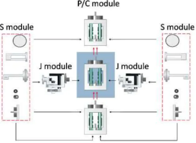
The system architecture is divided into modules, M-Robots and colonies. Modules are base system components and are classified in three types of hardware modules, i.e.,
power/control module (P/C), joint module (J) and special-ized module (S) as shown in Fig. 1 and also software
mod-ules, i.e., master module and slave module.
The design of the SMART modules aims to balance com-plexity with functionality. The goal is to build robots (M-Robots) that offer movement flexibility whilst allowing a variety of locomotion modes and reconfiguration capabili-ties.
P/C module
Figure 1. Three types of modules may be com-bined to form different robot configurations
The desired goal when dealing with communication ar-chitecture is for M-Robots to behave as robots that cooper-ate with each other. Moreover, that M-Robot configuration can change during task execution, either by docking or
un-Figure 2. The SMART System
docking modules to/from itself. For such an objective, syn-chronization and communication mechanisms are essential. Figure 2 shows a scenario where two M-Robots cooperate as a colony to execute a common task. There are 3 commu-nication channels. The first channel involves modules that belong to the same M-Robot. The second and third channels involve M-Robots and/or control stations. The three com-munication channels are enabled through CAN bus, Blue-tooth (BT) and RF-video technologies.
2.1 Intra-robot communication
Intra M-Robot communication refers to communication between P/C modules. Since elements are mechanically linked, it is performed via CAN bus technology. CAN bus is widely used in industrial environments since its application in modular robots offers considerable advantages. One im-portant CAN bus feature is transmission speed, which can reach 1 Mbit/s, hence, all the inner M-Robot communica-tions are executed via CAN bus.
2.2 Inter-robot communication
Master Software Module
Slave Software Module
Figure 3. Master and slave modules
2.3 Master and slave software modules
The master software module (MsM) manages external communications (via BT) and synchronizes the slave soft-ware modules (SsM) within the M-Robot configuration. The master module of each M-Robot is responsible for pre-processing the commands and dispatching the correspond-ing command to the rest of the slave modules via CAN bus. The information sent internally within the M-Robot are low-level commands, i.e., references for position con-trol loops, information for synchronization and both sensor and actuator data as shown in Fig. 3 . The slave modules re-ceive the message via CAN bus and execute the desired low-level commands. The MsM and/or SsM are downloaded into the P/C module. The P/C module contains the elec-tronic boards, the system power source, the communication peripherals, the mechanisms which physically connect the other types of modules and, depending on the robot con-figuration, may contain up to two software modules, i.e., MsM-SsM, MsM-MsM or SsM-SsM.
3 Synchronizing M-Robot modules using
Intra-communication
The M-Robot displays robot behavior thanks to module synchronization. This global behavior is required to move the M-Robot as a unit. This is a key feature in implement-ing collaborative behavior in a robot team. For example, in some modular robot configurations, in order to complete an action such as displacement of the modular robot, it would require simultaneous similar movements across numerous modules. In other words, it would require starting and fin-ishing all joint module movements at the same instant of time. With this type of synchronization it is possible to ex-ecute complex tasks.
One of the problems in distributed computational sys-tems, is the lack of a global clock [10]. This is a hand-icap for carrying out concurrent actions in a coordinated
way. Several approaches have been proposed to overcome this problem and the one used most is the message-passing method [11]. From the computational point of view, modu-lar robots are a set of processing units joined by a communi-cation bus. Therefore, message-passing methods are seen as a possible solution to synchronization problems in modular robots. However, many messages are needed to synchronize different processes. We propose a closed-loop discrete time method, which keeps all system clocks in the same phase and period, using a single short message in every cycle. The period of that cycle can be longer (seconds) than the control cycle period (milliseconds, typically the period of timer in-terruption). The method needs a periodic signal acting as a trigger for the closed loop. This signal is generated by the master module for every N control cycles and consists of a high priority short CAN message. In theory, all modules receive the message at the same time, but this is not cor-rect. Each time the message is received, a local timer (tick counter) is reset and its previous values are used to correct the local timer period, i.e., there is a counter that counts the ticks of a local timer (ticks of DSP clock) between every two consecutive synchronizing signals. When a synchro-nizing message enters the process, the current counter value is used to recalculate the local timer period. Consequently the counter is reset. Note that this process occurs in every single module.
TÍ+Í — arctan C xTi+t
Ñ ' (1)
Where:
C: Num. of control cycles; T¿: Current local timer period. t: Current cycle timer ticks; N: Ctrl, cycles / synch, period.
The master module creates a synchronization signal. It counts the number of interrupts generated by its timer until 300 units, and a message is then delivered to the slave
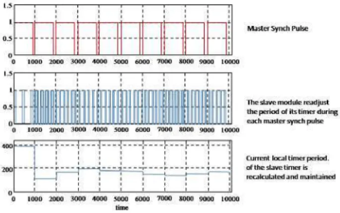
mod-M a s t e r Synch Pulse
0 1000 2000 3000 4000 5000 6000 7000 8000 9000 10000
The slave m o d u l e readjust t h e p e r i o d o f its t i m e r d u r i n g . j j each m a s t e r synch pulse 0 1000 2000 3000 4000 5000 6000 7000 8000 9000 10000
Current local t i m e r p e r i o d , o f t h e slave t i m e r is recalculated a n d m a i n t a i n e d
0 1000 2000 3000 4000 5000 6000 7000 8000 9000 1000G time
Figure 4. Synchronization using Intra-robot communication
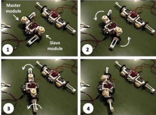
ules. The slave modules receive the message and adjust the period of their timer. To pick up the synchronization sig-nal, a low level interrupter message associated with the suc-cessful reception of a message in a defined mailbox is pro-grammed. Once the message has been received, the period of every slave timer is recalculated following the equation (1) and all the modules clocks should have the same phase and period, as shown in Fig. 4. In this way actions can be executed in a coordinated manner. This algorithm for mod-ule synchronization achieves single robot behavior with the M-Robot. For example, using the above method it is possi-ble to change from one modular robot configuration to an-other configuration with simultaneous joint movements, as shown in Fig. 5. The starting-stopping time for any mo-tor is below one millisecond. Synchronization is required in order to properly execute trajectories or in other cases, simultaneous forces are required for manipulation tasks.
Figure 5. A synchronized 2M-Robot structure
dinator of tasks.While the master module synchronizes the slave modules, it periodically sends a signal (pulse A) to the control station via BT indicating its synchronization signal. In order to synchronize a second M-Robot from the colony, it is required to acquire a second signal from the second master module. The second M-Robot executes the same previous process, i.e., it periodically sends a signal (pulse B) to the computer. At this time, the control station has two sig-nals originating from each M-Robot. To be more specific, each signal originates from the master module of each M-Robot. The control station calculates the clock skew (CS) between pulse B with respect to pulse A, represented by equation CS = CA{t) - CB(t).
Once the difference between pulse A and pulse B is cal-culated, the difference of internal counts between master modules is then calculated according to the CS. As a con-sequence, it then proceeds to correct the internal count of one of the modules with the information sent by the control station via BT. The robot receiving the count modification command will adjust its internal count to that value of the internal count of the reference robot. Thus, synchroniza-tion is achieved for both robots. The mosynchroniza-tion control loops are executed at the same time, thereby enabling the execu-tion of simultaneous movements in the robots (Fig. 6). The timing calculations do account for communication delays which are expected with BT message transmission. The op-erator can set the period of transmission of the sync signal for the robots as well as the minimum allowable gap in syn-chronization signals. When not allowing a minimum CS be-tween the robots, the algorithm would constantly calculate a count correction of one of the robots due to the variabil-ity of the communication delays via BT and the computer calculation.
4 Synchronizing a colony of M-Robots using
the inter-communication
The main idea of synchronizing a colony of modular robots is coordination in the execution of its tasks. Simul-taneous actions require synchronized joint movements that would otherwise not be correctly achieved. For instance, an object which has to be lifted between two or more robots, an object which has to be moved through a passage, etc. Co-ordinated movements are vital to accomplish such a task in an optimal way. In the M-Robot, the slave modules are syn-chronized by means of intra-robot communication, i.e., the master module periodically sends a synchronization signal by CAN bus to the slave modules to readjust their timer or control loop. Now, the idea is to synchronize master mod-ules of each M-Robot. In order to achieve the desired syn-chronization, a control station (PC) is used as the main
coor-\ . masters t y"
NO
"1
Count Value
< ^ >
-N O
Interpolator
1
Interpolator 1
"1
Master
Figure 7. Intra-robot communication allows synchronization within the 4M-Robot mod-ules for changing configuration with simul-taneous joint movements.
5 Experiments and results
The experiments that are described below show the be-havior of the colony and the way the robots act separately when synchronized. The first experiment consists of test-ing the synchronization via the Intra-robot communication method. As presented earlier in section 3, Fig. 5, the syn-chronization within a 2M-Robot is accomplished, i.e., the master module synchronizes the slave module. Considering the scalability of the system, a new experiment is performed with a 4M-Robot, i.e., the master module should synchro-nize three slave modules. The test consists of changing from the mobile configuration to the four-legs configuration. The movement coordination is crucial for this specific task. Fig. 7 shows the 4M-Robot movements during the execution of the task.
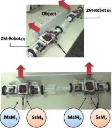
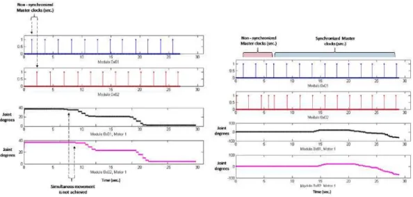
The second experiment consists of testing the synchro-nization via Inter-robot communication to push an object. The scenario consists of a colony composed of two 2M-Robots, as shown in Fig. 8. Each 2M-Robot has a MsM which constantly transmits the synchronization signal to the control station (via BT) and to its SsM (via Intra-robot com-munication). At the control station two signals from both MsM are received, i.e., a blue pulse from the master mod-ule originating from one of the two 2M-Robot (1) and a red pulse from the second master module as shown in Fig. 9. A CS exists between them and if the robots receive a com-mand to move during that period of time, the tasks executed by both 2M-Robots would not be synchronized.
The encoder value variation situated at each actuator shows the instance of time when the joint movement is ex-ecuted. One of the actuators from the 2M-Robot (1) be-gins the movement before the actuator from the second 2M-Robot (2). This implies that a simultaneous task cannot be
Figure 8. Synchronizing a modular robot colony for cooperative tasks
achieved, as shown in Fig. 10 (left). Each robot will ex-ecute commands, according to their own internal control loop. Applying the synchronization method via inter-robot communication to the colony the synchronization results are detailed in Fig. 9. One can see that the second mas-ter module receives a synchronization signal to correct its own count. The following pulse signal of the second master module is in synchronization with the first master module. The third graph displays the CS between both master soft-ware modules. It is clear how the CS decreases after the robots are synchronized. Figure 10 (right) displays a syn-chronized modular robot colony utilizing inter-robot com-munication. The encoder values from two actuators, each one from each 2M-robot are illustrated to demonstrate the coordinated joint movement. The joint movement of each M-Robot begins at the same time and it shares equal behav-ior during the test.
Master docks (sec.) clocks (sec.)
D 2 4 6 8 10 12 14 16 Module Uxilil
Maslcr sync Q g „ puis.- ptfC.)
0J 1—J L-J 1 1 1 1 1 U 1 L
D 2 4 6 0 10 12 14 IB
Modulo 0x02
Delay between E Mastersync n l pulses (sec.) Uf
-I ' ' ' ' ' ' ' ' ! D 2 4 6 8 10 12 14 16
TinWsKl
Non - synchronized Master clocks (sec.)
T
-Non - synchronized Master clocks (sec.)
1
-" dub 0*01
' '
t UH .
; % _
H 5 | 10 15 70 25 30 Modulo 0x01, Moior 1
Í • V .
^ V .
J 5 ! 10 15 20 25 30 I Modulo 0x02, Moler 1
V
Synchronized Master clocks (sec.)
I
: :
i 5 10 15 20 25 30 Modula 0x01
:
-i 5 10 15 20 25 30 Modulo 0x02
i 5 10 15 20 25 X Modulo DxD1. Motor 1
Modulo fluTO Mntnr 1
T i m e (sec.)
Figure 10. Non-sync joint movements (left) and Sync joint movements into the colony (right)
6 Conclusion
Intra-robot communication is used to synchronize a set of two or more physically connected robot modules. Inter-robot communication is used to synchronize modular Inter-robots that are not physically connected between them. By com-bining both type of communications a colony of reconfig-urable modular robots may be synchronized to perform si-multaneous actions regardless of robot configuration. It has been demonstrated that the synchronization is achieved between the modules of the M-Robot, as well as be-tween the M-Robots within the colony. Test results of the synchronization method implemented in the SMART sys-tem demonstrate optimized performance during cooperative tasks.
7 Acknowledgment
The authors would like to thank CICYT and CONACYT for financing this research project. The SMART project has been financed within the Industrial Design and Production Program (DPI2003-00759 and DPI-2006-06493).
References
[1] M. Yim, Ying Zhang, K. Roufas, D. Duff, C. Elder-shaw, "Connecting and disconnecting for chain self-reconfiguration with PolyBot," IEEE/ASME Transac-tions on Mechatronics, vol.7, no.4, pp.442-451, 2002.
[2] S. Murata, E. Yoshida, A. Kamimura, H. Kurokawa, K. Tomita, S. Kokaji, "M-TRAN: self-reconfigurable modular robotic system," IEEE/ASME Transactions on Mechatronics, vol.7, no.4, pp.431-441, 2002.
[3] G. McKee, P. Schenker, "Networked robotics," in Proc. Sensor Fusion and Decentralized Control in Robotic Systems III, SPIE, 2000.
[4] Navarro-Serment, L.E., Grabowski, R., Paredis, C.J.J., Khosla, P.K., "Millibots," IEEE Robotics & Automa-tion Magazine, vol.9, no.4, pp.31-40, 2002.
[5] R. Gusella, S. Zatti, "The accuracy of the clock syn-chronization achieved by TEMPO in Berkeley UNIX 4.3BSD," IEEE Transactions on Software Engineer-ing, vol.15, no.7, pp.847-853, 1989.
[6] 1.1. Blekhman, P. S. Landa, M. G. Rosenhlum, "Syn-chronization and chaotization in interacting dynami-cal systems," ASME Applied Mechanidynami-cal Review, vol. 48, pp.733-752, 1995.
[7] H. Nijmeijer, A. Rodriguez-Angeles, "Synchroniza-tion of mechanical systems," World Scientific Publish-ing, Singapore, 2003.
[8] Y H. Liu, Y Xu, and M. Bergeman, "Coopera-tion control of multiple manipulators with passive joints," IEEE Trans. Robotics and Automation., vol.
15, pp.258-267, 1999.
[9] A. Rodriguez-Angeles and H. Nijmeijer, "Coordina-tion of two robot manipulators based on posi"Coordina-tion mea-surements only," International Journal of Control, vol. 14,pp.l311-1323, 2001.
[10] Chow, Randy, and T. Johnson., "Distributed Operating Systems and Algorithms," Addison-Wesley, 1997.