Dual-Band Circular Polarized Slot Array Antenna in Substrate
Integrated Waveguide using Two Propagation Modes
for Communication Satellites Transceivers
Iv´an Herrero-Sebasti´an* and C´esar Benavente-Peces
Abstract—A novel dual-band circularly-polarized slot array antenna aimed at LEO satellites communications where up-link and down-link operate at different frequencies is introduced. By using higher order modes, the slots can be placed at points where current distributions are null for the fundamental mode. According to this idea, at the receiver frequency band the slots are placed to be excited by mode T E10 currents distribution, and at the transmitting band slots are forced to radiate
according to mode T E20 currents distribution. A matching load termination is used to generate
the required travelling wave to obtain the circular polarization, introducing low dissipation losses. Additionally, in this investigation an antenna feeder is also designed. Both the feeder and the slot antenna array are designed using Substrate Integrated Waveguide (SIW). The use of SIW makes easier the design of the transitions from the array to the microstrip input lines and the grounded-coplanar termination as well, relaxing fabrication constraints and tolerance.
1. INTRODUCTION
The requirement of global mobile coverage has driven the need of deploying a satellite system to provide world-wide internet access, specially where terrestrial systems do not. Because manufacturing a satellite for medium or high orbits is very expensive, low-cost air devices such as balloons and mini-satellites flying at the low-orbit have recently appeared [1, 2]. As the mobile phones for terrestrial systems are becoming smaller and smaller, devices to receive signals from those constellations are expected to have reduced size too. In this investigation, operating frequency bands are those commonly used incubesat
constellations, as well as spaceX and One Web systems, i.e., 10.7–11.7 GHz band for RX (down-link) and 14–14.5 GHz band for TX (up-link).
The proposed antenna is designed in Substrate Integrated Waveguide (SIW), a novel technology which allows implementing, among a variety of microwave components [3], slot arrays in planar circuits instead of using common waveguides with large height, while keeping all their advantages. Moreover, its light weight and low cost make these antennas appropriate to be used in mass portable devices.
While other slot-antennas usually use blended arms to resonate at several frequencies [4, 5], this paper introduces a novel antenna with two independent groups of slots, one for each frequency band. In addition, since One Web mini-satellites constellation produces circularly polarized (CP) electromagnetic waves (EMW), the receiver land-antenna implemented must be CP too. As a rule, complex and big-size shapes are used to obtain circular polarization in rectangular waveguides [6, 7], such as an array of corner-truncated polarization-rotation metasurface cells shown in [8]. SIW Multi-band Slots Array Antennas design is analyzed in [9], where CP approach is not considered. As a new contribution, circular polarization is considered in the novel antenna to improve the link performance.
Received 1 July 2019, Accepted 16 August 2019, Scheduled 29 August 2019
* Corresponding author: Iv´an Herrero-Sebasti´an ([email protected]).
In the proposed approach, to obtain two frequency-independent groups of slots, it is necessary to propagate several modes along the SIW. Whereas cavity resonators are usually designed for multi-frequency radiators [10, 11], a traveling wave [12] is required to add circular polarization too. Given that metalized vias are used in the SIW, no TM modes can propagate, and only T Emn modes will be used.
2. ANTENNA DESIGN
The cutoff frequency for T Emn propagating modes (or just T Em0), since the SIW is a planar circuit
and its small height ‘b’ can be neglected, basically depends on vias diameter ‘d’, their spacing ‘s’, and the distance between rows ‘a’. The propagation frequency of modeT Emn is given by
fmn= 2cπ
mπ aeff
2
+
nπ
b
2
. (1)
whereaeff is given by
aeff =a+ d
2
0.95s. (2)
and the resulting wavelength is obtained from
λs(f) = λ0(f)
1−
fc f
2. (3)
According to these equations, a 18 mm-width SIW, whose substrate is FR-4 (r = 4.4), would ensure theT E20 mode propagation at 14.5 GHz. There are two couples of longitudinal/transversal slots. One
couple is fed by T E10 at 11.2 GHz (RX band) and the other byT E20 at 14.25 GHz (TX band). These
couples are represented in Fig. 1.
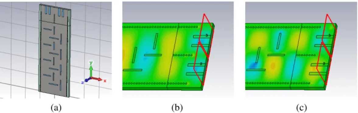
Longitudinal slots are totally independent of each other while TX-transversal slot introduces some spurious coupling to the RX one, affecting its radiation pattern, as shown in Fig. 2 where maximum tangential surface currents are shown.
(a) (b) (c) (d)
Figure 1. H-field distribution along the antenna. (a) TE10 Hx. (b) TE10 Hy. (c) TE20 Hx. (d) TE20
Hy.
(a) (b)
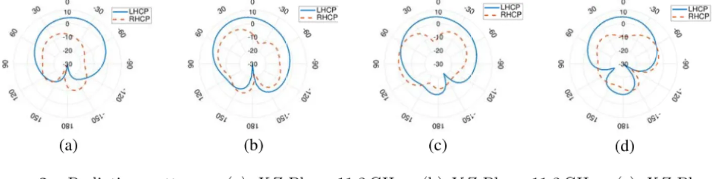
Whereas in a SIW cavity resonators Hx and Hy are in phase, forcing linear polarization, and in a traveling-wave SIW they are shifted 90◦ from each other at the same point to achieve the circular polarization. The two couples of slots set a single ‘Radiator Block’, and according to slots placement, when SIW is fed through the upper side, it is Right-Handed-Circular-Polarized (RHCP) and LHCP (Left-HCP) when it is done through the lower side. In our design, the selected polarization is LHCP, obtaining decoupling losses of 0.5 dB at 11.2 GHz and 0.2 dB at 14.25 GHz, which are usual values in a CP-antenna. Co-polar and Cross-polar diagrams are shown in Fig. 3.
(b)
(a) (c) (d)
Figure 3. Radiation patterns. (a) XZ-Plane 11.2 GHz. (b) Y Z-Plane 11.2 GHz. (c) XZ-Plane 14.25 GHz. (d)Y Z-Plane 14.25 GHz.
3. ANTENNA FEEDER
A 3-layer stack-up is used to design the feeding system. Top face holds a tap transition [13] from microstrip to a Band-Pass-Filter (BPF) in SIW, accomplished with metalized posts, for removing higher frequencies from TX band in the RX path, whereas a 180◦-phase shifter is placed at the bottom face to create the wave which will feed theT E20 mode. This structure is shown in Fig. 4.
(b) (a)
Figure 4. Dual-mode feeder. (a) Top. (b) Bottom.
The SIW phase shifter design is based on [14], but some modifications have been added, as follows. Since TX bandwidth is 3.5%, the equations system for the design can be relaxed to two widths instead of three, forcing the phase shift at f0 to be:
Φ(f0) =l1(β1(f0)−β2(f0)) +l2β2(f0). (4)
where l1 is the length of the shortest SIW; l1+l2 is the largest one length; and β1 and β2 are the
propagation constants from the right and left-placed SIWs, respectively, whose effective width aeff is
subtracted from Eq. (2), defined as:
βi(f0) =
2
πf0√eff
300
2
+
π aeffi
2
Finally, by using Eq. (4) and fixing effective widthsaeff in order to cut lower band propagation as
constants, lengths l1 and l2 can be found by solving, based on LMS methods, Equation (6), where Δf
is the desired bandwidth.
Φ(f0) = Φ(f0+ Δf). (6)
Figure 5 presents the feeder performance, where filter provides a discrimination between bands above 10 dB, and phase shifter achieves±5◦ phase unbalance within TX band.
(b) (a)
Figure 5. Antenna feeder performance. (a) BPF filter frequency response. (b) Phase difference between paths.
4. ARRAY DESIGN
To obtain a desired directivity, the‘Radiator Block’ from Fig. 1 is uniformly distributed along the SIW, building the array and match-ended with a proper termination for both propagation modes, as shown in Fig. 6. Slots length for TE10 is set to 5.5 mm, whereas TE20 mode works with 4.5 mm-slots. Since,
only for TE10propagation, illumination fromHy for vertical slot is lower than theHxone for its couple,
the first one is 10% longer to get a good circular polarization.
(b)
(a) (c)
Figure 6. Detailed array layout. (a) Slots placement for 4 RB. (b) Matched-end forT E10. (c)
Matched-end forT E20.
Since both slots for every couple are fed at the same point, the resulting equivalent circuit is that depicted in Fig. 7. Z(f, m) andY(f, m) are the impedance and admittance respectively of slots for any frequency in the T Em0 mode. Applying numerical methods available in appropriate simulators makes
Yr x(f , m) 2
Zr x(f m )
Yr x(f , m) 2 λs(fr x)
4 Ztx (f m )
λs(fr x) 2
z0
RB RB
(b) (a)
Figure 7. Equivalent circuits. (a) Single radiator block. (b) Array.
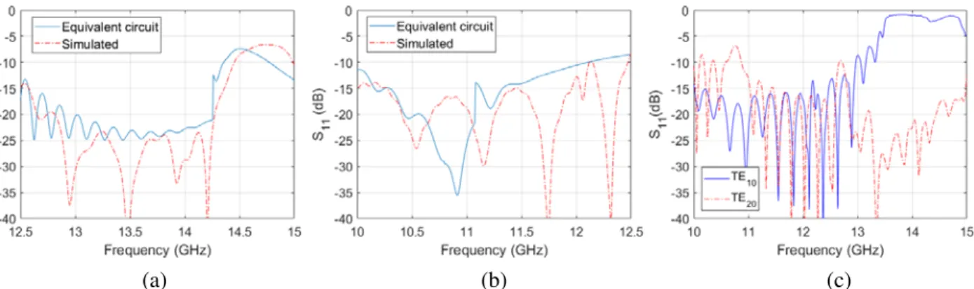
Reflection magnitude of the equivalent circuit from Fig. 7 fits simulator results for a 20 radiator blocks implementation in Fig. 8, with a chosen uniform distance between radiator elements multiple of
λs(fRx)
4 to enhance RX bandwidth as the first approach, but poor RL for TX band is got.
(b)
(a) (c)
Figure 8. Simulated and theoretical return losses. (a) Return loss TE20. (b) Return loss TE10.
(c) Simulated RL after adjust.
For this design, each couple of slots can be tuned independently by a nonuniform slot distribution, which allows placing and adjusting each couple at different distances to optimize RL for both propagation modes, as seen in Fig. 8(c), and obtain the same beam pointing for different frequency bands if required, since distance between couple of slots also controls the main beam angle.
As stated before, radiation from TX slots is not interfered by RX couple, but it does in the converse case. Since transversal TX slot is shifted Wsiw
4 from SIW center,T E10 illuminates the slot
√
2/2 times the energy with respect to RX one. Hence, the array factor for RX slots is given by:
AF(θ, φ) = N−1
n=0
1 +
√
2 2 e
ΩxeΩy(1) eΩy(2) (7)
where:
Ωx = jβsiwW4siw sin(θ) cos(φ) (8a)
Ωy(i) = βsiwd(i) (1 +jsin(θ) sin(φ)) (8b)
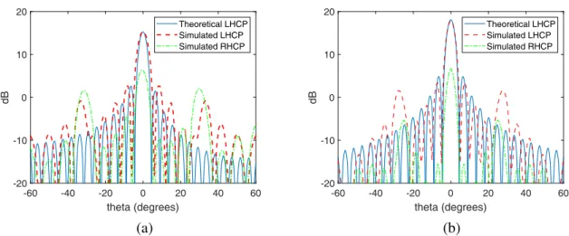
N is the number of radiator blocks, and d(1) is the transmission line length shown in the circuit of Fig. 7(a) and d(2) in Fig. 7(b). Theoretical and simulated results of a 20-elements array antenna are shown in Fig. 9.
-60 -40 -20 0 20 40 60 theta (degrees) -20 -10 0 10 20 dB Theoretical LHCP Simulated LHCP Simulated RHCP
-60 -40 -20 0 20 40 60
theta (degrees) -20 -10 0 10 20 dB Theoretical LHCP Simulated LHCP Simulated RHCP (b) (a)
Figure 9. Array factor radiation pattern for LHCP and RHCP at Y Z plane. (a) 11.2 GHz T E10.
(b) 14.25 GHzT E20.
5. CONCLUSION
In this paper, a novel slot antenna based on substrate integrated waveguide (SIW) has been investigated, aimed at satellite communications for world-wide coverage. The antenna shows three relevant features at the same time: dual-band operation, bands independent tuning, and circular polarization. Such a behaviour is achieved by exploiting two propagation modes and placing the group of slots properly to get the required currents distribution. Return losses, as well as the array factor, have been simulated and compared with theoretical models to validate the results. High directivity, low decoupling losses for circular polarization, and a main lobe aiming close to the end-fire direction make the antenna appropriate for portable transceiver in mini-satellites systems, like One Web constellation, whose physical factors are a hard constraint which requires new designs and technologies as SIW.
REFERENCES
1. Nagpal, L. and K. Samdani, “Project loon: Innovating the connectivity worldwide,”IEEE RTEICT, May 2017.
2. Barnett, R. J., “OneWeb non-geostationary satellite system,” FCC, 2013.
3. Chou, H. and Y. Chen, “Phased array antenna modules with dual ports for independent transmitting and receiving beam-forming networks,”IEEE APEMC, 2017.
4. Srivastava, A., R. Kumar, A. Buswas, and M. Akhtar, “Dual-band c-shaped circular slot SIW antenna,” IEEE International Conference on iAIM, 2017.
5. De, R., B. B. Chowdhury, and M. Bhowmik, “A novel design of dual frequency SIW slot antenna,”
International Conference on Signal Processing and Integrated Networks, June 2016.
6. Yang, S., A. E. Fathy, and S. Suleiman, “Synthesis of a travelling wave slotted substrate integrated waveguide array with dual-circular polarization,” IEEE International Microwave Symposium Digest, 2013.
7. Kulkarni, P. B. and D. V. D. Weide, “An X-band circularly polarized substrate integrated waveguide slot antenna,” IEEE International Symposium on Antennas and Propagation, June 2016.
8. Yang, W., Q. Meng, W. Che, L. Gu, and Q. Xue, “Low-profile wideband dual-circularly polarized metasurface antenna array with large beamwidth,” IEEE Antennas and Wireless Propagation Letters, Vol. 17, No. 9, 1613–1616, 2018.
10. Mohan, M. P., A. Alphones, and F. Karim, “Triple band Siw cavity backed slot antenna,” IEEE Asia Pacific Microwave Conference, 2017.
11. Wu, C. T. M. and T. Itoh, “An X-band dual-mode antenna using substrate integrated waveguide cavity for simultaneous satellite and terrestrial links,” IEEE Asia-Pacific Pacific Microwave Conference, 2014.
12. Martinez-Ros, A. J., M. Bozzi, and M. Pasian, “Double sided SIW leaky-wave antenna with increased directivity in the E-plane,” IEEE Trans. on Antennas and Propagation, Vol. 66, No. 6, 3130–3135, 2018.
13. Du, M., J. Xu, Y. Dong, and X. Ding, “LTCC SIW-vertical fed-dipole array fed by a microstrip network with tapered microstrip-to-SIW transitions for wideband millimeter-wave applications,”
IEEE Antennas and Wireless Prop. Letters, Vol. 16, 1953–1956, 2017.
14. Cheng, Y. J., K. Wu, and W. Hong, “Substrate integrated waveguide (SIW) broadband compensating phase shifter,”IEEE International Microwave Symposium Digest, July 2009. 15. Stanculovic, S., “Theoretical synthesis and experimental measurements for slotted waveguide