DIPLOMADO DE PROFUNDIZACION CISCO PRUEBA DE HABILIDADES PRÁCTICAS CCNP
LUIS CARLOS LEGUIZAMON ROJAS
UNIVERSIDAD NACIONAL ABIERTA Y A DISTANCIA - UNAD ESCUELA DE CIENCIAS BÁSICAS TECNOLOGÍA E INGENIERÍA -ECBTI
INGENIERIA DE TELECOMUNICACIONES SOGAMOSO-BOYACA
DIPLOMADO DE PROFUNDIZACION CISCO PRUEBA DE HABILIDADES PRÁCTICAS CCNP
LUIS CARLOS LEGUIZAMON ROJAS
Diplomado de opción de grado presentado para optar el título de INGENIERO DE TELECOMUNICACIONES
DIRECTOR:
MSc. GERARDO GRANADOS ACUÑA
UNIVERSIDAD NACIONAL ABIERTA Y A DISTANCIA - UNAD
ESCUELA DE CIENCIAS BÁSICAS TECNOLOGÍA E INGENIERÍA – ECBTI INGENIERIA DE TELECOMUNICACIONES
NOTA DE ACEPTACION
_________________________ _________________________ _________________________ _________________________ _________________________
_________________________ Firma Del Presidente Del Jurado
_________________________ Firma Del Jurado
_________________________ Firma Del Jurado
4
AGRADECIMIENTOS
5
CONTENIDO
AGRADECIMIENTOS ... 4
CONTENIDO ... 5
LISTA DE TABLAS ... 6
LISTA DE FIGURAS ... 7
RESUMEN ... 10
ABSTRACT ... 10
INTRODUCCION ... 11
DESARROLLO ... 12
1. ESCENARIO 1 ... 12
6
LISTA DE TABLAS
7
LISTA DE FIGURAS
Ilustración 1. Diagrama de topología requerida ... 12
Ilustración 2. Topología de red implementada ... 13
Ilustración 3. Configuración R1 ... 14
Ilustración 4. Configuración R2 ... 16
Ilustración 5. Configuración R3 ... 17
Ilustración 6. Configuración OSPFv3 para R2 ... 19
Ilustración 7. configuración ospfv3 para R3 ... 21
Ilustración 8. configuración interfaz área 1 en R2 ... 22
Ilustración 9. configuración interfaz área 0 para R3 ... 24
Ilustración 10. Configuración área stubby en R2 ... 25
Ilustración 11. Propagación rutas por defecto R3 ... 27
Ilustración 12. Configuración EIGRP en R1 ... 29
Ilustración 13. configuración EIGRP para R2 ... 31
Ilustración 14. Configuración en R2 ... 32
Ilustración 15. Redistribución mutua entre OSPF y EIGRP para IPv4 e IPV6 R2 ... 34
Ilustración 16. Publicidad de ruta 192.168.3.0/24 a R1 mediante lista de distribución y acl en R2 ... 36
Ilustración 17. Comando show ip route en R1 ... 37
Ilustración 18. Comando show ipV6 route en R1 ... 37
Ilustración 19. comando show ip eigrp neighbors R1 ... 37
Ilustración 20. Comando show ipv6 neighbors R1 ... 38
Ilustración 21. Comando Show ip route para R2 ... 38
Ilustración 22. Comando show ipv6 route para R2 ... 38
Ilustración 23. Comando show ip-ipv6 neighbors R2 ... 38
Ilustración 24. Comando show ipv6 ospf R2 ... 39
Ilustración 25. Comando show ipv6 ospf database ... 39
Ilustración 26. comando show ipv6 route R3 ... 39
Ilustración 27. comando show ipv6 route R3 ... 39
Ilustración 28. comando show ipv6 ospf database ... 39
Ilustración 29. comando ping ipv4 e ipv6 desde R1 ... 40
Ilustración 30. ping ipv6 desde R2 ... 40
Ilustración 31. ping ipv4 en R2 ... 41
Ilustración 32. Ping ipv4 desde R3 ... 41
Ilustración 33. Ping ipv6 desde R3 ... 42
Ilustración 34. comando show running-config en R1 ... 42
Ilustración 35. comando show running-config R2 ... 43
Ilustración 36. Comando Show running-config R3 ... 44
8
Ilustración 38. topología implementada en packet tracer ... 46
Ilustración 39. apagado de todas las interfaces en dls1 ... 49
Ilustración 40. apagado de interfaces en DLS2 ... 49
Ilustración 41. Apagado de interfaces en ALS1 ... 50
Ilustración 42. apagado de interfaces en ALS2 ... 51
Ilustración 43. Asignación de nombres a cada switch ... 52
Ilustración 44. validación comando show EtherChannel summary en DLS1 y DLS2 ... 53
Ilustración 45. Port channel 1 en DLS1 ... 55
Ilustración 46. Port channel 1 en ALS1 ... 56
Ilustración 47. Port channel 2 en DLS2 ... 57
Ilustración 48. Port channel 2 en ALS2 ... 59
Ilustración 49. Port channel 4 en DLS1 ... 60
Ilustración 50. Port channel 4 en ALS2 ... 61
Ilustración 51. Port channel 3 en DLS2 ... 62
Ilustración 52. Port channel 3 en ALS1 ... 63
Ilustración 53. verificación puertos DLS1 ... 64
Ilustración 54. configuración vlan 800 como nativa DlS1 ... 65
Ilustración 55. configuración vlan 800 nativa en DLS2 ... 66
lustración 56. configuración vlan 800 nativa ALS1 ... 67
Ilustración 57. configuración vlan 800 nativa ALS2 ... 68
Ilustración 58. Configuración DLS1 para utilizar VTP versión 2 ... 68
Ilustración 59. Configuración ALS1 para utilizar VTP versión 2 ... 69
Ilustración 60. Configuración ALS2 para utilizar VTP versión 2 ... 69
Ilustración 61. Comando Vtp Status DLS1 ... 70
Ilustración 62. Validación cliente Vtp status ALS1 y ALS2 ... 70
Ilustración 63. validación VLANs solicitadas ... 72
Ilustración 64. Suspensión vlan 434... 73
Ilustración 65.Habilitación vtp mode transparent ... 73
Ilustración 66. suspensión vlan 434 ... 74
Ilustración 67. Creación de vlan 567 y negación de paso ... 75
Ilustración 68. configuración Spanning-tree en DLS1 ... 75
Ilustración 69. configuración Spanning-tree en DLS2 ... 75
Ilustración 70. validación de trunk ports ... 76
Ilustración 71. configuración puertos de acceso ... 77
Ilustración 72. Verificación vlan e interfaz trunk en DLS1 ... 78
Ilustración 73. Verificación vlan e interfaz en DLS2 ... 79
Ilustración 74. Verificación vlan e interfaz en ALS1 ... 79
Ilustración 75. Verificación vlan e interfaz en ALS2 ... 80
9
Ilustración 77. Verificación etherchannels DLS2 ... 82
Ilustración 78. Verificación Spanning-tree DLS1 ... 83
Ilustración 79. Verificación Spanning-tree en DLS1 ... 84
10
RESUMEN
El desarrollo de este documento de prueba de habilidades consiste en el proceso de conceptualización de los conocimientos y temas aprendidos en el área de Redes y Networking para CISCO Routing y Switching de los módulos de CCNA y el Diplomado de profundización de cisco CCNP, a su vez realizando la aplicación práctica de estos, en programas de simulación lógica diseñados para este fin. Su principal objetivo, es medir los conocimientos y capacidad de aplicación de los conceptos aprendidos en esta rama de la Electrónica por el estudiante, aplicando sus conocimientos aprendidos a lo largo del desarrollo de los diversos modulo del Diplomado Cisco CCNP.
ABSTRACT
The development of this skills test document consists of the process of conceptualization of the knowledge and topics learned in the area of Networks and Networking for CISCO Routing and Switching of the CCNA modules and the CCNP cisco deepening Diploma, in turn realizing the practical application of these, in logical simulation programs designed for this purpose.
11
INTRODUCCION
Hoy en día, la importancia que han adquirido las redes LAN, WAN y MAN, entre otras, se ha incrementado notablemente debido a los constantes cambios en las tecnologías, generan diferentes desafíos y retos para los especialistas en Telecomunicaciones, que abren un mundo de posibilidades al obtener los conocimientos necesarios, mediante los módulos de CCNA y CCNP ofrecidos por CISCO.
12
DESARROLLO 1. ESCENARIO 1
Una empresa de confecciones posee tres sucursales distribuidas en las ciudades de Bogotá, Medellín y Bucaramanga, en donde el estudiante será el administrador de la red, el cual deberá configurar e interconectar entre sí cada uno de los dispositivos que forman parte del escenario, acorde con los lineamientos establecidos para el direccionamiento IP, protocolos de enrutamiento y demás aspectos que forman parte de la topología de red.
Ilustración 1. Diagrama de topología requerida
13
Ilustración 2. Topología de red implementada
1. Configurar las interfaces con las direcciones IPv4 e IPv6 que se muestran en la topología de red.
2. Ajustar el ancho de banda a 128 kbps sobre cada uno de los enlaces seriales ubicados en R1, R2, y R3 y ajustar la velocidad de reloj de las conexiones de DCE según sea apropiado.
R1>en R1#conf t
Enter configuration commands, one per line. End with CNTL/Z. R1(config)#ipv6 unicast-routing
R1(config)#int g0/0
R1(config-if)#ip address 192.168.110.1 255.255.255.0 % 192.168.110.0 overlaps with Serial0/0/0
R1(config-if)#ipv6 address 2001:db8:acad:110::1/64
%GigabitEthernet0/0: Error: 2001:DB8:ACAD:110::/64 is overlapping with 2001:DB8:ACAD:110::/64 on Serial0/0/0
R1(config-if)#no shut
% 192.168.110.0 overlaps with Serial0/0/0
14
R1(config-if)#ip address 192.168.9.1 255.255.255.0 % 192.168.9.0 overlaps with Serial0/0/1
R1(config-if)#ipv6 address 2001:db8:acad:90::1/64
%Serial0/0/0: Error: 2001:DB8:ACAD:90::/64 is overlapping with 2001:DB8:ACAD:90::/64 on Serial0/0/1
R1(config-if)#clock rate 128000 R1(config-if)#bandw
R1(config-if)#bandwidth 128 R1(config-if)#no shut
Ilustración 3. Configuración R1
15 ^
% Invalid input detected at '^' marker. R2#conf t
Enter configuration commands, one per line. End with CNTL/Z. R2(config)#ipv6 unicast-routing
R2(config)#int g0/0
R2(config-if)#ip address 192.168.2.1 255.255.255.0 % 192.168.2.0 overlaps with Serial0/0/0
R2(config-if)#ipv6 address 2001:db8:acad:b::1/64
%GigabitEthernet0/0: Error: 2001:DB8:ACAD:B::/64 is overlapping with 2001:DB8:ACAD:B::/64 on Serial0/0/0
R2(config-if)#no shutdown
% 192.168.2.0 overlaps with Serial0/0/0
GigabitEthernet0/0: incorrect IP address assignment R2(config-if)#int s0/0/0
R2(config-if)#ip address 192.168.9.2 255.255.255.0 % 192.168.9.0 overlaps with Serial0/0/1
R2(config-if)#int s0/0/1 R2(config-if)#shut
%LINK-5-CHANGED: Interface Serial0/0/1, changed state to administratively down R2(config-if)#int s0/0/0
R2(config-if)#ipv6 address 2001:db8:acad:90::2/64
%Serial0/0/0: Error: 2001:DB8:ACAD:90::/64 is overlapping with 2001:DB8:ACAD:90::/64 on Serial0/0/1
R2(config-if)#bandwidth 128 R2(config-if)#
R2(config-if)#no shut R2(config-if)#int s0/0/1
R2(config-if)#ip address 192.168.9.5 255.255.255.0 R2(config-if)#ipv6 address 2001:db8:acad:91::1/64 R2(config-if)#clock rate 128000
R2(config-if)#bandw % Incomplete command. R2(config-if)#da
^
% Invalid input detected at '^' marker. R2(config-if)#bandw
16
%LINK-5-CHANGED: Interface Serial0/0/1, changed state to down R2(config-if)#
Ilustración 4. Configuración R2
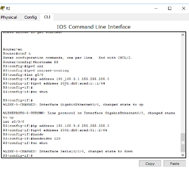
Router>en Router#conf t
Enter configuration commands, one per line. End with CNTL/Z. Router(config)#hostname R3
R3(config)#ipv6 uni
R3(config)#ipv6 unicast-routing R3(config)#int g0/0
R3(config-if)#ip address 192.168.3.1 255.255.255.0 R3(config-if)#ipv6 address 2001:db8:acad:c::1/64 R3(config-if)#
R3(config-if)#no shut
R3(config-if)#
%LINK-5-CHANGED: Interface GigabitEthernet0/0, changed state to up
%LINEPROTO-5-UPDOWN: Line protocol on Interface GigabitEthernet0/0, changed state to up
int s0/0/0
17 R3(config-if)#bandwidth 128
R3(config-if)#no shut
%LINK-5-CHANGED: Interface Serial0/0/0, changed state to down R3(config-if)#
Ilustración 5. Configuración R3
3. En R2 y R3 configurar las familias de direcciones OSPFv3 para IPv4 e IPv6. Utilice el identificador de enrutamiento 2.2.2.2 en R2 y 3.3.3.3 en R3 para ambas familias de direcciones.
18 R2>en
R2#conf t
Enter configuration commands, one per line. End with CNTL/Z. R2(config)#rout
R2(config)#router ospf 1
R2(config-router)#address-family ipv4 unicast ^
% Invalid input detected at '^' marker. R2(config-router)#router-id 2.2.2.2 R2(config-router)#exit-address-family ^
% Invalid input detected at '^' marker.
R2(config-router)#address-family ipv6 unicast ^
% Invalid input detected at '^' marker. R2(config-router)#router-id 2.2.2.2 R2(config-router)#exit-address-family ^
% Invalid input detected at '^' marker. R2(config-router)#
R2#
19
Ilustración 6. Configuración OSPFv3 para R2
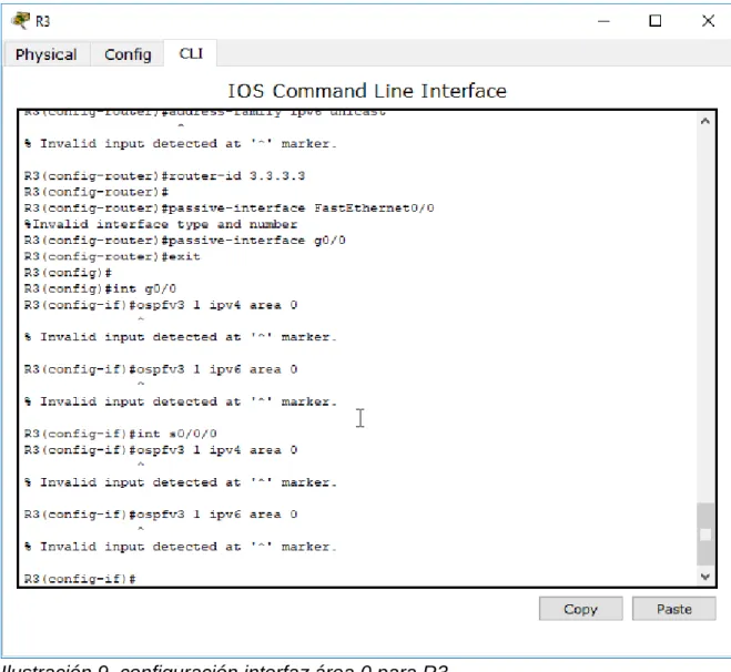
R3>en R3#conf t
Enter configuration commands, one per line. End with CNTL/Z. R3(config)#router ospf 1
R3(config-router)#address-family ipv4 unicast ^
20 ^
% Invalid input detected at '^' marker. R3(config-router)#exit-address-family ^
% Invalid input detected at '^' marker. R3(config-router)#
R3#
%SYS-5-CONFIG_I: Configured from console by console
R3#conf t
Enter configuration commands, one per line. End with CNTL/Z. R3(config)#router ospf 1
R3(config-router)#address-family ipv6 unicast ^
% Invalid input detected at '^' marker. R3(config-router)#router-id 3.3.3.3 R3(config-router)#
R3(config-router)#passive-interface FastEthernet0/0 %Invalid interface type and number
R3(config-router)#passive-interface g0/0 R3(config-router)#exit
21
Ilustración 7. configuración ospfv3 para R3
4. En R2, configurar la interfaz F0/0 en el área 1 de OSPF y la conexión serial entre R2 y R3 en OSPF área 0.
R2#conf t
Enter configuration commands, one per line. End with CNTL/Z. R2(config)#int g0/0
R2(config-if)#ospf 1 ? % Unrecognized command
R2(config-if)#ospf 1 ospfv3 1 ipv4 area 1 ^
22 R2(config-if)#ospf 1 ospfv3 1 ipv6 area 1 ^
% Invalid input detected at '^' marker. R2(config-if)#int s0/0/1
R2(config-if)#ospf 1 ospfv3 1 ipv4 area 1 ^
% Invalid input detected at '^' marker. R2(config-if)#ospf 1 ospfv3 1 ipv6 area 1 ^
% Invalid input detected at '^' marker. R2(config-if)#
23
5. En R3, configurar la interfaz F0/0 y la conexión serial entre R2 y R3 en OSPF área 0.
R3(config)#
R3(config)#int g0/0
R3(config-if)#ospfv3 1 ipv4 area 0 ^
% Invalid input detected at '^' marker.
R3(config-if)#ospfv3 1 ipv6 area 0 ^
% Invalid input detected at '^' marker.
R3(config-if)#int s0/0/0
R3(config-if)#ospfv3 1 ipv4 area 0 ^
% Invalid input detected at '^' marker.
R3(config-if)#ospfv3 1 ipv6 area 0 ^
% Invalid input detected at '^' marker.
24
Ilustración 9. configuración interfaz área 0 para R3
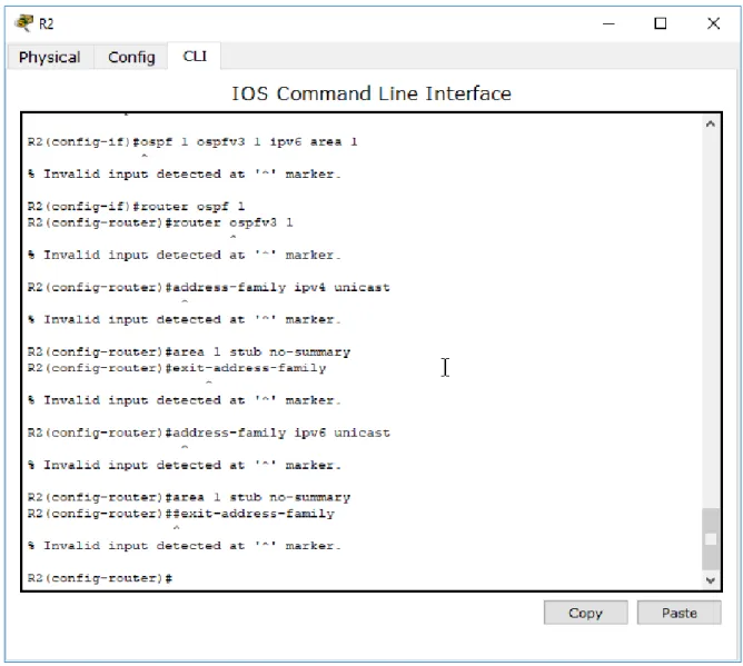
6. Configurar el área 1 como un área totalmente Stubby.
R2(config-if)#router ospf 1
R2(config-router)#router ospfv3 1 ^
% Invalid input detected at '^' marker.
R2(config-router)#address-family ipv4 unicast ^
25 R2(config-router)#exit-address-family ^
% Invalid input detected at '^' marker.
R2(config-router)#address-family ipv6 unicast ^
% Invalid input detected at '^' marker. R2(config-router)#area 1 stub no-summary R2(config-router)##exit-address-family
26
7. Propagar rutas por defecto de IPv4 y IPv6 en R3 al interior del dominio OSPFv3. Nota: Es importante tener en cuenta que una ruta por defecto
es diferente a la definición de rutas estáticas.
R3(config)#router ospf 1
R3(config-router)#router ospfv3 1 ^
% Invalid input detected at '^' marker.
R3(config-router)#address-family ipv4 unicast ^
% Invalid input detected at '^' marker.
R3(config-router)#default-information originate always ^
% Invalid input detected at '^' marker.
R3(config-router)##exit-address-family ^
% Invalid input detected at '^' marker.
R3(config-router)#address-family ipv6 unicast ^
% Invalid input detected at '^' marker.
R3(config-router)#default-information originate always ^
% Invalid input detected at '^' marker.
R3(config-router)#exit-address-family ^
27
Ilustración 11. Propagación rutas por defecto R3
8. Realizar la configuración del protocolo EIGRP para IPv4 como IPv6. Configurar la interfaz F0/0 de R1 y la conexión entre R1 y R2 para EIGRP con el sistema autónomo 101. Asegúrese de que el resumen automático está desactivado.
9. Configurar las interfaces pasivas para EIGRP según sea apropiado. Se desarrolla punto 8 y 9
R1(config)#router eigrp ^
28 R1(config)#router eigrp DUAL-STACK ^
% Invalid input detected at '^' marker.
R1(config)#address-family ipv4 unicast autonomous-system 4 ^
% Invalid input detected at '^' marker. R1(config)#af-interface FastEthernet0/0 ^
% Invalid input detected at '^' marker. R1(config)#
R1(config)#passive-interface ^
% Invalid input detected at '^' marker. R1(config)#exit-af-interface
^
% Invalid input detected at '^' marker. R1(config)#topology base
^
% Invalid input detected at '^' marker. R1(config)#exit-af-topology
^
% Invalid input detected at '^' marker. R1(config)#network 192.168.9.0 0.0.0.3 ^
% Invalid input detected at '^' marker. R1(config)#network 192.168.110.0 0.0.0.3 ^
% Invalid input detected at '^' marker. R1(config)#
R1(config)#eigrp router-id 1.1.1.1 ^
% Invalid input detected at '^' marker. R1(config)#
R1(config)#exit-address-family ^
% Invalid input detected at '^' marker.
R1(config)#address-family ipv6 unicast autonomous-system 6 ^
% Invalid input detected at '^' marker. R1(config)#af-interface g0/0
29 % Invalid input detected at '^' marker. R1(config)#passive-interface
^
% Invalid input detected at '^' marker. R1(config)#
R1(config)#exit-af-interface ^
% Invalid input detected at '^' marker. R1(config)#topology base
^
% Invalid input detected at '^' marker. R1(config)#
R1(config)#exit-af-topology ^
% Invalid input detected at '^' marker. R1(config)#eigrp router-id 1.1.1.1 ^
% Invalid input detected at '^' marker. R1(config)#exit-address-family
^
% Invalid input detected at '^' marker.
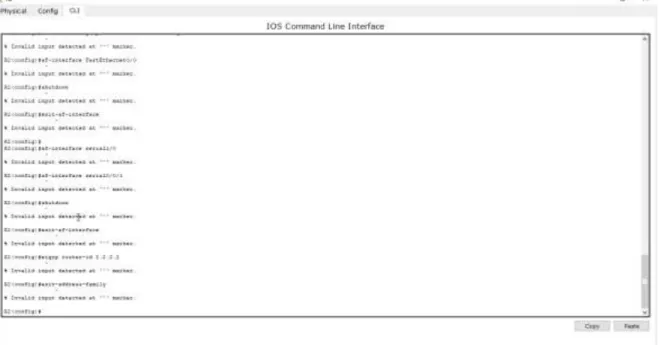
30 R2>en
R2#conf t
Enter configuration commands, one per line. End with CNTL/Z. R2(config)#router eigrp DUAL-STACK
^
% Invalid input detected at '^' marker.
R2(config)#address-family ipv4 unicast autonomous-system 4 ^
% Invalid input detected at '^' marker. R2(config)#network 192.168.9.0 0.0.0.3 ^
% Invalid input detected at '^' marker. R2(config)#eigrp router-id 2.2.2.2 ^
% Invalid input detected at '^' marker. R2(config)#exit-address-family
^
% Invalid input detected at '^' marker.
R2(config)#address-family ipv6 unicast autonomous-system 6 ^
% Invalid input detected at '^' marker. R2(config)#af-interface FastEthernet0/0 ^
% Invalid input detected at '^' marker. R2(config)#shutdown
^
% Invalid input detected at '^' marker. R2(config)#exit-af-interface
^
% Invalid input detected at '^' marker. R2(config)#
R2(config)#af-interface serial1/0 ^
% Invalid input detected at '^' marker. R2(config)#af-interface serial0/0/1 ^
31 ^
% Invalid input detected at '^' marker. R2(config)#exit-af-interface
^
% Invalid input detected at '^' marker. R2(config)#eigrp router-id 2.2.2.2 ^
% Invalid input detected at '^' marker. R2(config)#exit-address-family
Ilustración 13. configuración EIGRP para R2
R2(config)#router eigrp DUAL-STACK ^
% Invalid input detected at '^' marker.
R2(config)#address-family ipv4 unicast autonomous-system 4 ^
% Invalid input detected at '^' marker. R2(config)#topology base
^
% Invalid input detected at '^' marker. R2(config)#distribute-list R3-to-R1 out ^
32
R2(config)#redistribute ospfv3 1 metric 10000 100 255 1 1500 ^
% Invalid input detected at '^' marker. R2(config)#exit-af-topology
^
% Invalid input detected at '^' marker.
Ilustración 14. Configuración en R2
33 R2(config)#router eigrp DUAL-STACK ^
% Invalid input detected at '^' marker.
R2(config)#address-family ipv4 unicast autonomous-system 4 ^
% Invalid input detected at '^' marker. R2(config)#topology base
^
% Invalid input detected at '^' marker. R2(config)#distribute-list R3-to-R1 out ^
% Invalid input detected at '^' marker.
R2(config)#redistribute ospfv3 1 metric 10000 100 255 1 1500 ^
% Invalid input detected at '^' marker. R2(config)#exit-af-topology
^
% Invalid input detected at '^' marker.
R2(config)#address-family ipv6 unicast autonomous-system 6 ^
% Invalid input detected at '^' marker. R2(config)#topology base
^
% Invalid input detected at '^' marker.
R2(config)#redistribute ospf 1 metric 10000 100 255 1 1500 ^
% Invalid input detected at '^' marker. R2(config)#
34
Ilustración 15. Redistribución mutua entre OSPF y EIGRP para IPv4 e IPV6 R2
11. En R2, de hacer publicidad de la ruta 192.168.3.0/24 a R1 mediante una lista de distribución y ACL.
R2(config-router)#ip acce
R2(config-router)#ip access-list standard Re-to-R1 R2(config-std-nacl)#ip access-list standard R3-to-R1 R2(config-std-nacl)#remark ACL to filter 192.168.3.0/24 R2(config-std-nacl)#deny 192.168.3.0 0.0.0.255
R2(config-std-nacl)#permit any
35 ^
% Invalid input detected at '^' marker. R2(config-std-nacl)#redistribute eigrp 4 ^
% Invalid input detected at '^' marker.
R2(config-std-nacl)#address-family ipv6 unicast ^
% Invalid input detected at '^' marker. R2(config-std-nacl)#
R2(config-std-nacl)#redistribute eigrp 6 ^
% Invalid input detected at '^' marker. R2(config-std-nacl)#exit-address-family ^
36
Ilustración 16. Publicidad de ruta 192.168.3.0/24 a R1 mediante lista de distribución y acl en R2
Parte 2: Verificar conectividad de red y control de la trayectoria.
37
Ilustración 17. Comando show ip route en R1
Ilustración 18. Comando show ipV6 route en R1
38
Ilustración 20. Comando show ipv6 neighbors R1
Packet tracer no soporta estos comandos para su configuración, igualmente se realiza la configuración solicitada
Ilustración 21. Comando Show ip route para R2
Ilustración 22. Comando show ipv6 route para R2
Ilustración 23. Comando show ip-ipv6 neighbors R2
39
Ilustración 24. Comando show ipv6 ospf R2
Ilustración 25. Comando show ipv6 ospf database
Ilustración 26. comando show ipv6 route R3
Ilustración 27. comando show ipv6 route R3
Ilustración 28. comando show ipv6 ospf database
40
Ilustración 29. comando ping ipv4 e ipv6 desde R1
41
Ilustración 31. ping ipv4 en R2
42
Ilustración 33. Ping ipv6 desde R3
3. Verificar que las rutas filtradas no están presentes en las tablas de enrutamiento de los routers correctas.
43
44
45 2. ESCENARIO 2
Una empresa de comunicaciones presenta una estructura Core acorde a la topología de red, en donde el estudiante será el administrador de la red, el cual deberá configurar e interconectar entre sí cada uno de los dispositivos que forman parte del escenario, acorde con los lineamientos establecidos para el direccionamiento IP, etherchannels, VLANs y demás aspectos que forman parte del escenario propuesto.
Topología de red
46
Ilustración 38. topología implementada en packet tracer
Parte 1: Configurar la red de acuerdo con las especificaciones.
a. Apagar todas las interfaces en cada switch.
Switch>EN Switch#conf t
Enter configuration commands, one per line. End with CNTL/Z. Switch(config)#int
Switch(config)#interface range fas
Switch(config)#interface range fastEthernet 0/1-24, gi
Switch(config)#interface range fastEthernet 0/1-24, gigabitEthernet 0/1-2 Switch(config-if-range)#shut
%LINK-5-CHANGED: Interface FastEthernet0/1, changed state to administratively down
%LINK-5-CHANGED: Interface FastEthernet0/2, changed state to administratively down
%LINK-5-CHANGED: Interface FastEthernet0/3, changed state to administratively down
%LINK-5-CHANGED: Interface FastEthernet0/4, changed state to administratively down
%LINK-5-CHANGED: Interface FastEthernet0/5, changed state to administratively down
%LINK-5-CHANGED: Interface FastEthernet0/13, changed state to administratively down
%LINK-5-CHANGED: Interface FastEthernet0/14, changed state to administratively down
47
%LINK-5-CHANGED: Interface FastEthernet0/16, changed state to administratively down
%LINK-5-CHANGED: Interface FastEthernet0/17, changed state to administratively down
%LINK-5-CHANGED: Interface FastEthernet0/18, changed state to administratively down
%LINK-5-CHANGED: Interface FastEthernet0/19, changed state to administratively down
%LINK-5-CHANGED: Interface FastEthernet0/20, changed state to administratively down
%LINK-5-CHANGED: Interface FastEthernet0/21, changed state to administratively down
%LINK-5-CHANGED: Interface FastEthernet0/22, changed state to administratively down
%LINK-5-CHANGED: Interface FastEthernet0/23, changed state to administratively down
%LINK-5-CHANGED: Interface FastEthernet0/24, changed state to administratively down
%LINK-5-CHANGED: Interface GigabitEthernet0/1, changed state to administratively down
%LINK-5-CHANGED: Interface GigabitEthernet0/2, changed state to administratively down
Switch(config-if-range)#
%LINK-5-CHANGED: Interface FastEthernet0/6, changed state to administratively down
%LINEPROTO-5-UPDOWN: Line protocol on Interface FastEthernet0/6, changed state to down
48
%LINEPROTO-5-UPDOWN: Line protocol on Interface FastEthernet0/7, changed state to down
%LINK-5-CHANGED: Interface FastEthernet0/8, changed state to administratively down
%LINEPROTO-5-UPDOWN: Line protocol on Interface FastEthernet0/8, changed state to down
%LINK-5-CHANGED: Interface FastEthernet0/9, changed state to administratively down
%LINEPROTO-5-UPDOWN: Line protocol on Interface FastEthernet0/9, changed state to down
%LINK-5-CHANGED: Interface FastEthernet0/10, changed state to administratively down
%LINEPROTO-5-UPDOWN: Line protocol on Interface FastEthernet0/10, changed state to down
%LINK-5-CHANGED: Interface FastEthernet0/11, changed state to administratively down
%LINEPROTO-5-UPDOWN: Line protocol on Interface FastEthernet0/11, changed state to down
%LINK-5-CHANGED: Interface FastEthernet0/12, changed state to administratively down
%LINEPROTO-5-UPDOWN: Line protocol on Interface FastEthernet0/12, changed state to down
Switch#
49
Ilustración 39. apagado de todas las interfaces en dls1
50
51
Ilustración 42. apagado de interfaces en ALS2
b. Asignar un nombre a cada switch acorde al escenario establecido.
DLS1>en DLS1#conf t
Enter configuration commands, one per line. End with CNTL/Z. DLS1(config)#hos
52
Ilustración 43. Asignación de nombres a cada switch
c. Configurar los puertos troncales y Port-channels tal como se muestra en el diagrama.
1) La conexión entre DLS1 y DLS2 será un EtherChannel capa-3 utilizando LACP. Para DLS1 se utilizará la dirección IP 10.12.12.1/30 y para DLS2 utilizará
10.12.12.2/30.
Para esto, primero creamos el portchannel capa 3 y después lo asignamos a las interfaces, en este caso solo se hace para DLS1 y DLS2
DLS1# DLS1#conf t
Enter configuration commands, one per line. End with CNTL/Z. DLS1(config)#int
DLS1(config)#interface por
DLS1(config)#interface port-channel 12 DLS1(config-if)#no sh
DLS1(config-if)#no sw
DLS1(config-if)#no switchport
DLS1(config-if)#ip address 10.12.12.1 255.255.255.252 DLS1(config-if)#exit
DLS1(config)#int ra
DLS1(config)#int range fa0/11-12 DLS1(config-if-range)#no sw
DLS1(config-if-range)#no switchport DLS1(config-if-range)#chan
DLS1(config-if-range)#channel-group 12 mode active DLS1(config-if-range)#exit
DLS1(config)#
53 DLS2(config-if)#no sw
DLS2(config-if)#no switchport
DLS2(config-if)#ip address 10.12.12.2 255.255.255.252 DLS2(config-if)#exit
DLS2(config)#interface range fa0/11-12 DLS2(config-if-range)#no sw
DLS2(config-if-range)#channel-group 12 mode active DLS2(config-if-range)#exit
DLS2(config)# DLS2#
%SYS-5-CONFIG_I: Configured from console by console
Ilustración 44. validación comando show EtherChannel summary en DLS1 y DLS2
2) Los Port-channels en las interfaces Fa0/7 y Fa0/8 utilizarán LACP.
DLS1# DLS1#conf t
Enter configuration commands, one per line. End with CNTL/Z. DLS1(config)#int ran
DLS1(config)#int range fa0/7-8 DLS1(config-if-range)#sw
DLS1(config-if-range)#switchport trun DLS1(config-if-range)#switchport trunk en
DLS1(config-if-range)#switchport trunk encapsulation dot1q DLS1(config-if-range)#sw
54 DLS1(config-if-range)#switchport mode tr DLS1(config-if-range)#switchport mode trunk DLS1(config-if-range)#chann
DLS1(config-if-range)#channel-gr
DLS1(config-if-range)#channel-group 1 mode ac DLS1(config-if-range)#channel-group 1 mode active DLS1(config-if-range)#
Creating a port-channel interface Port-channel 1 no shut
55
Ilustración 45. Port channel 1 en DLS1
ALS1(config)#int ra
ALS1(config)#int range fa0/7-8 ALS1(config-if-range)#sw
ALS1(config-if-range)#switchport tr
ALS1(config-if-range)#switchport trunk en ALS1(config-if-range)#switchport trunk enca
ALS1(config-if-range)#switchport trunk encapsulation dot1q ^
% Invalid input detected at '^' marker.
ALS1(config-if-range)#switchport mode trunk
ALS1(config-if-range)#channel-group 1 mode active ALS1(config-if-range)#
Creating a port-channel interface Port-channel 1
56
Ilustración 46. Port channel 1 en ALS1
DLS2(config)#int ran
DLS2(config)#int range fa0/7-8 DLS2(config-if-range)#sw
DLS2(config-if-range)#switchport tru DLS2(config-if-range)#switchport trunk en
DLS2(config-if-range)#switchport trunk encapsulation dot1q DLS2(config-if-range)#sw
DLS2(config-if-range)#switchport mod DLS2(config-if-range)#switchport mode tr DLS2(config-if-range)#switchport mode trunk
57 DLS2(config-if-range)#
Creating a port-channel interface Port-channel 2 no shut
%LINK-5-CHANGED: Interface FastEthernet0/7, changed state to down
%LINK-5-CHANGED: Interface FastEthernet0/8, changed state to down DLS2(config-if-range)#
Ilustración 47. Port channel 2 en DLS2
58
Enter configuration commands, one per line. End with CNTL/Z. ALS2(config)#int ra
ALS2(config)#int range fa0/7-8
ALS2(config-if-range)#switchport trunk encapsulation dot1q ^
% Invalid input detected at '^' marker. ALS2(config-if-range)#sw
ALS2(config-if-range)#switchport mode tru ALS2(config-if-range)#switchport mode trunk
ALS2(config-if-range)#channel-group 2 mode active ALS2(config-if-range)#
Creating a port-channel interface Port-channel 2 no shu
ALS2(config-if-range)#no shutdown
59
Ilustración 48. Port channel 2 en ALS2
3) Los Port-channels en las interfaces F0/9 y fa0/10 utilizará PAgP. DLS1#conf t
Enter configuration commands, one per line. End with CNTL/Z. DLS1(config)#int ra
DLS1(config)#int range fa0/9-10
DLS1(config-if-range)#switchport trunk encapsulation dot1q DLS1(config-if-range)#switchport mode trunk
DLS1(config-if-range)#channel-group 4 mode desirable DLS1(config-if-range)#
60 no shut
Ilustración 49. Port channel 4 en DLS1
ALS2(config)#int ra
ALS2(config)#int range fa0/9-10
ALS2(config-if-range)#switchport trunk encapsulation dot1q ^
% Invalid input detected at '^' marker. ALS2(config-if-range)#swi
ALS2(config-if-range)#switchport mode tru ALS2(config-if-range)#switchport mode trunk
61 Creating a port-channel interface Port-channel 4 no shut
Ilustración 50. Port channel 4 en ALS2
DLS2#conf t
Enter configuration commands, one per line. End with CNTL/Z. DLS2(config)#int ra
DLS2(config)#int range fa0/9-10
DLS2(config-if-range)#switchport trunk encapsulation dot1q DLS2(config-if-range)#switchport mode trunk
62 Creating a port-channel interface Port-channel 3 no shut
Ilustración 51. Port channel 3 en DLS2
ALS1(config)#int ra
ALS1(config)#int range fa0/9-10
ALS1(config-if-range)# switchport trunk encapsulation dot1q ^
% Invalid input detected at '^' marker.
ALS1(config-if-range)#switchport mode trunk
63 ALS1(config-if-range)#
Creating a port-channel interface Port-channel 3 no shut
Ilustración 52. Port channel 3 en ALS1
4) Todos los puertos troncales serán asignados a la VLAN 800 como la VLAN nativa. con el siguiente comando validamos los puertos actuales
64
Ilustración 53. verificación puertos DLS1
DLS1(config)#interface Po1 DLS1(config-if)#sw
DLS1(config-if)#switchport tru DLS1(config-if)#switchport trunk nat DLS1(config-if)#switchport trunk native vl
DLS1(config-if)#switchport trunk native vlan 800 DLS1(config-if)#exit
DLS1(config)#i
%CDP-4-NATIVE_VLAN_MISMATCH: Native VLAN mismatch discovered on Port-channel 1 (800), with ALS1 FastEthernet0/7 (1).
%CDP-4-NATIVE_VLAN_MISMATCH: Native VLAN mismatch discovered on Port-channel 1 (800), with ALS1 FastEthernet0/8 (1).
%CDP-4-NATIVE_VLAN_MISMATCH: Native VLAN mismatch discovered on Port-channel 1 (800), with ALS1 Port-Port-channel 1 (1).
DLS1(config)#int Po4
DLS1(config-if)#switchport trunk native vlan 800 DLS1(config-if)#exit
65
Ilustración 54. configuración vlan 800 como nativa DlS1
DLS2(config)#int Po2 DLS2(config-if)#swi
DLS2(config-if)#switchport tu DLS2(config-if)#switchport t
DLS2(config-if)#switchport trunk na DLS2(config-if)#switchport trunk native v
DLS2(config-if)#switchport trunk native vlan 800 DLS2(config-if)#exit
DLS2(config)#int Po3
66
Ilustración 55. configuración vlan 800 nativa en DLS2
ALS1(config)#int Po1 ALS1(config-if)#
%CDP-4-NATIVE_VLAN_MISMATCH: Native VLAN mismatch discovered on Port-channel 3 (1), with DLS2 FastEthernet0/9 (800).
%CDP-4-NATIVE_VLAN_MISMATCH: Native VLAN mismatch discovered on Port-channel 3 (1), with DLS2 FastEthernet0/10 (800).
%CDP-4-NATIVE_VLAN_MISMATCH: Native VLAN mismatch discovered on Port-channel 3 (1), with DLS2 Port-Port-channel 3 (800).
sw
ALS1(config-if)#switchport tr
ALS1(config-if)#switchport trunk na ALS1(config-if)#switchport trunk native v
ALS1(config-if)#switchport trunk native vlan 800 ALS1(config-if)#exit
ALS1(config)#int Po3
67
Ilustración 56. configuración vlan 800 nativa ALS1
ALS2(config)#int
ALS2(config)#interface Po2 ALS2(config-if)#sw
ALS2(config-if)#switchport tu ALS2(config-if)#switchport t
ALS2(config-if)#switchport trunk na ALS2(config-if)#switchport trunk native vl
ALS2(config-if)#switchport trunk native vlan 800 ALS2(config-if)#exit
ALS2(config)#interface Po4
68
Ilustración 57. configuración vlan 800 nativa ALS2
d. Configurar DLS1, ALS1, y ALS2 para utilizar VTP versión 3 1) Utilizar el nombre de dominio UNAD con la contraseña cisco123 DLS1#conf t
Enter configuration commands, one per line. End with CNTL/Z. DLS1(config)#vtp d
DLS1(config)#vtp domain UNAD
Changing VTP domain name from NULL to UNAD DLS1(config)#vtp pass
DLS1(config)#vtp password cisco123
Setting device VLAN database password to cisco123 DLS1(config)#vtp ve
DLS1(config)#vtp version 2 DLS1(config)#
69 ALS1#conf t
Enter configuration commands, one per line. End with CNTL/Z. ALS1(config)#vtp domain UNAD
Domain name already set to UNAD. ALS1(config)#vtp pass cisco123
Setting device VLAN database password to cisco123 ALS1(config)#vtp version 2
ALS1(config)#
Ilustración 59. Configuración ALS1 para utilizar VTP versión 2
ALS2>en ALS2#conf t
Enter configuration commands, one per line. End with CNTL/Z. ALS2(config)#vtp do
ALS2(config)#vtp domain UNAD Domain name already set to UNAD. ALS2(config)#vtp pass
ALS2(config)#vtp password cisco123
Setting device VLAN database password to cisco123 ALS2(config)#vtp vers
ALS2(config)#vtp version 2 ALS2(config)#
70
2) Configurar DLS1 como servidor principal para las VLAN. DLS1>en
DLS1#conf t
Enter configuration commands, one per line. End with CNTL/Z. DLS1(config)#vtp mode ser
DLS1(config)#vtp mode server Device mode already VTP SERVER. DLS1(config)#
Ilustración 61. Comando Vtp Status DLS1
3) Configurar ALS1 y ALS2 como clientes VTP. ALS1(config)#vtp mode cl
ALS1(config)#vtp mode client
Setting device to VTP CLIENT mode. ALS1(config)#
ALS2(config)#
ALS2(config)#vtp mode client
Setting device to VTP CLIENT mode.
71
e. Configurar en el servidor principal las siguientes VLAN:
Tabla 1. Configuración VLAN servidor
72
Ilustración 63. validación VLANs solicitadas
f. En DLS1, suspender la VLAN 434.
DLS1#CONF T
Enter configuration commands, one per line. End with CNTL/Z. DLS1(config)#VLAN 434
DLS1(config-vlan)#STA DLS1(config-vlan)#sta
DLS1(config-vlan)#state suspend
73
Ilustración 64. Suspensión vlan 434
g. Configurar DLS2 en modo VTP transparente VTP utilizando VTP versión 2, y configurar en DLS2 las mismas VLAN que en DLS1.
DLS2(config)#vtp mode DLS2(config)#vtp mode tran
DLS2(config)#vtp mode transparent
Setting device to VTP TRANSPARENT mode. DLS2(config)#vtp ver
DLS2(config)#vtp version 2 DLS2(config)#
Ilustración 65.Habilitación vtp mode transparent
h. Suspender VLAN 434 en DLS2. DLS2(config)#vlan 434
DLS2(config-vlan)#state susp DLS2(config-vlan)#state susp ^
74
Ilustración 66. suspensión vlan 434
i. En DLS2, crear VLAN 567 con el nombre de CONTABILIDAD. La VLAN de CONTABILIDAD no podrá estar disponible en cualquier otro Switch de la red.
DLS2#conf t
Enter configuration commands, one per line. End with CNTL/Z. DLS2(config)#vlan 567
DLS2(config-vlan)#name CONTABILIDAD DLS2(config-vlan)#int por
DLS2(config-vlan)#int port-c DLS2(config-vlan)#exit DLS2(config)#int por
DLS2(config)#int port-channel 2 DLS2(config-if)#swi
DLS2(config-if)#switchport tru
DLS2(config-if)#switchport trunk allowed vlan exce DLS2(config-if)#switchport trunk allowed vlan except 567 DLS2(config-if)#int port-channel 3
75
Ilustración 67. Creación de vlan 567 y negación de paso
j. Configurar DLS1 como Spanning tree root para las VLAN 1, 12, 434, 800, 1010, 1111 y 3456 y como raíz secundaria para las VLAN 123 y 234.
DLS1>en DLS1#conf t
Enter configuration commands, one per line. End with CNTL/Z.
DLS1(config)#spanning-tree vlan 1,12,434,800,101,111,345 root primary DLS1(config)#spanning-tree vlan 123,234 root secondary
Ilustración 68. configuración Spanning-tree en DLS1
k. Configurar DLS2 como Spanning tree root para las VLAN 123 y 234 y como una raíz secundaria para las VLAN 12, 434, 800, 1010, 1111 y 3456.
DLS2(config)#spanning-tree vlan 123,234 root primary
DLS2(config)#spanning-tree vlan 1,12,434,800,101,111,345 root secondary DLS2(config)#
Ilustración 69. configuración Spanning-tree en DLS2
76
Ilustración 70. validación de trunk ports
m. Configurar las siguientes interfaces como puertos de acceso, asignados a las VLAN de la siguiente manera:
Tabla 2. Configuración puertos de acceso VLANs DLS1(config)#int fa0/6
DLS1(config-if)#sw
DLS1(config-if)#switchport mode DLS1(config-if)#switchport mode acc DLS1(config-if)#switchport mode access DLS1(config-if)#swi
77 DLS1(config-if)#sp
DLS1(config-if)#spannin
DLS1(config-if)#spanning-tree port DLS1(config-if)#spanning-tree portfast
%Warning: portfast should only be enabled on ports connected to a single host. Connecting hubs, concentrators, switches, bridges, etc... to this interface when portfast is enabled, can cause temporary bridging loops. Use with CAUTION
%Portfast has been configured on FastEthernet0/6 but will only have effect when the interface is in a non-trunking mode. DLS1(config-if)#no shut
78
Parte 2: conectividad de red de prueba y las opciones configuradas.
a. Verificar la existencia de las VLAN correctas en todos los switches y la asignación de puertos troncales y de acceso
79
Ilustración 73. Verificación vlan e interfaz en DLS2
80
Ilustración 75. Verificación vlan e interfaz en ALS2
81
82
Ilustración 77. Verificación etherchannels DLS2
83
84
85
86
CONCLUSIONES
Se realiza la configuración del escenario 1 mediante la aplicación de configuraciones OSPF y EIGRP a los protocolos IPv4 e IPv6.
Se aplican los conocimientos adquiridos a lo largo del Diplomado de profundización CISCO CCNP y los módulos CCNA estudiados a lo largo de la carrera actual.
Se configuran Switches con parámetros EtherChannel, VTP y portchannel en el escenario 2.
87
REFERENCIAS BIBLIOGRAFICAS
Teare, D., Vachon B., Graziani, R. (2015). CISCO Press (Ed). Implementing a Border Gateway Protocol (BGP) Solution for ISP Connectivity. Implementing Cisco IP Routing (ROUTE) Foundation Learning Guide CCNP ROUTE
300-101. Recuperado de
https://1drv.ms/b/s!AmIJYei-NT1IlnMfy2rhPZHwEoWx
Teare, D., Vachon B., Graziani, R. (2015). CISCO Press (Ed). OSPF Implementation. Implementing Cisco IP Routing (ROUTE) Foundation Learning Guide CCNP ROUTE 300-101. Recuperado de https://1drv.ms/b/s!AmIJYei-NT1IlnMfy2rhPZHwEoWx
Teare, D., Vachon B., Graziani, R. (2015). CISCO Press (Ed). EIGRP Implementation. Implementing Cisco IP Routing (ROUTE) Foundation Learning Guide CCNP ROUTE 300-101. Recuperado de https://1drv.ms/b/s!AmIJYei-NT1IlnMfy2rhPZHwEoWx
Teare, D., Vachon B., Graziani, R. (2015). CISCO Press (Ed). Manipulating Routing Updates. Implementing Cisco IP Routing (ROUTE) Foundation Learning Guide CCNP ROUTE 300-101. Recuperado de https://1drv.ms/b/s!AmIJYei-NT1IlnMfy2rhPZHwEoWx
88
Froom, R., Frahim, E. (2015). CISCO Press (Ed). Fundamentals Review. Implementing Cisco IP Switched Networks (SWITCH) Foundation Learning Guide CCNP SWITCH 300-115. Recuperado de https://1drv.ms/b/s!AmIJYei-NT1IlnWR0hoMxgBNv1CJ
Froom, R., Frahim, E. (2015). CISCO Press (Ed). Spanning Tree Implementation. Implementing Cisco IP Switched Networks (SWITCH) Foundation Learning Guide CCNP SWITCH 300-115. Recuperado dehttps://1drv.ms/b/s!AmIJYei-NT1IlnWR0hoMxgBNv1CJ