Evaluating pointing errors on ergodic capacity of DF
relay-assisted FSO communication systems
Rub´en Boluda-Ruiz
1, Antonio Garc´ıa-Zambrana
1, Beatriz Castillo-V´azquez
1and Carmen Castillo-V´azquez
2 1Dept. of Communications Engineering, University of M´alaga, Spain2Dept. of Statistics and Operations Research, University of M´alaga, Spain
E-mail:{rbr,agz,bcv}@ic.uma.es and [email protected]
Abstract—Ergodic capacity of decode-and-forward (DF) relay-assisted free-space optical (FSO) communication systems when line of sight is available is analyzed over gamma-gamma fading channels with pointing errors. Novel closed-form approximate ergodic capacity expression is obtained in terms of the H-Fox function for a 3-way FSO communication system when the α
-µ distribution to efficiently approximate the probability density function (PDF) of the sum of gamma-gamma with pointing errors variates is considered. Moreover, we present a novel asymptotic expression at high signal-to-noise ratio (SNR) for the ergodic capacity of DF relay-assisted FSO systems. The main contribution in this work lies in an in-depth analysis about the impact of pointing errors on the ergodic capacity for cooperative FSO systems. In order to maintain the same performance in terms of capacity, it is corroborated that the presence of pointing errors requires an increase in SNR, which is related to the fraction of the collected power at the receive aperture, i.e. A0. Simulation results are further demonstrated to confirm the accuracy and usefulness of the derived results.
Keywords—Free-space optical (FSO), cooperative communi-cations, decode-and-forward (DF), ergodic capacity, asymptotic ergodic capacity analysis, H-Fox function.
I. INTRODUCTION
Free-space optical (FSO) systems allow communication at data rates as high as hundreds of gigabits per second for a variety of applications [1]. However, the major impairment in FSO communication systems is the atmospheric turbulence, which produces fluctuations in the irradiance of the transmitted optical beam, as a result of random variations in the refractive index along the link [2]. Additionally, the high directivity of the transmitted beam in FSO systems, or building sway can produce an unsuitable alignment between transmitter and receiver and, hence, a greater deterioration in performance. In the last decade, several works have investigated the adoption of cooperative communications in the context of FSO systems in order to solve these inconveniences [3], [4], which have proved that cooperative communications are quite a efficient technique to satisfy the typical bit error-rate (BER) targets for FSO applications without much increase in hardware. Lately, there have been few studies on ergodic capacity for cooperative FSO systems, which have demonstrated that coop-erative communications are also able to increase the channel capacity [5]–[7]. In [5], the end-to-end ergodic capacity of dual-hop FSO system employing amplify-and-forward (AF) relaying is evaluated over gamma-gamma fading channels with pointing errors, by approximating the probability density function (PDF) of the end-to-end signal to noise ratio (SNR), by the α-µdistribution. In [6], [7], the capacity performance
of dual-hop subcarrier intensity modulation (SIM)-based FSO system with decode-and-forward (DF) and AF relay is evalu-ated, respectively, over gamma-gamma fading channels with pointing errors. The derived results are obtained in terms of special function known as generalized bivariate Meijers G-function (GBMGF). Previously, the ergodic capacity was analyzed for FSO communication links in [8]–[11], showing that ergodic capacity can be perfectly applied to FSO links, despite the fact that the atmospheric turbulence channels can be well described as slow fading or block fading channels and, hence, outage capacity becomes a more realistic measure of channel capacity than ergodic capacity in FSO systems.
However, to the best of the author’s knowledge, the study of the ergodic capacity for cooperative FSO systems wherein the line of sight is taken into account has not been studied yet. Motivated by this issue, the purpose of this work is to study the ergodic capacity for the bit-detect-and-forward (BDF) cooperative protocol presented in [4], over gamma-gamma fading channels with pointing errors when line of sight is available. As concluded in [4], the BDF cooperative protocol is able to achieve a higher diversity order, strongly dependent not only on the relay location but also on the pointing errors. In this work, a novel approximate closed-form ergodic capacity expression is obtained in terms of the H-Fox function for a 3-way FSO communication system when the irradiance of the transmitted optical beam is susceptible to moderate-to-strong turbulence conditions, following a gamma-gamma distribution of parameters a and b, or pointing error effects, following a misalignment fading model where the effect of beam width, detector size and jitter variance is considered. Here, as pro-posed in [12], the α-µ distribution is used in order to obtain a closed-form expression for the distribution of the sum of gamma-gamma with pointing errors variates. Unlike [5], here, a numerical observation of the α-µ parameters is included in order to evaluate how these parameters are affected by pointing errors. Moreover, we present an asymptotic expression at high signal-to-noise ratio (SNR) for the ergodic capacity of DF relay-assisted FSO systems, showing a greater and robust capacity when line of sight is available compared to a direct transmission without cooperative communication. The main contribution in this work lies in an in-depth analysis about the impact of pointing errors on the ergodic capacity for cooperative FSO systems. In order to maintain the same performance in terms of capacity, it is corroborated that the presence of pointing errors requires an increase in SNR, which is related to the fraction of the collected power at the receive aperture, i.e. A0 and, hence, not being dependent of the relay
II. SYSTEM ANDCHANNELMODEL
We adopt a three-node cooperative system based on three separate FSO links, as shown in Fig. 1, assuming laser sources intensity-modulated and ideal non-coherent (direct-detection) receivers. The cooperative strategy works in two phases. In the
S
Source
R Relay
D
Destination
dSD yR
xR
Fig. 1.Block diagram of the considered 3-way FSO system.
first phase, the source node S sends its own data to the relay node R and the destination node D. In the second phase, the relay node R sends the received data from the source node S in the first phase to the destination node D. In this fashion, the relay node R detects each code bit to “0” or “1” and sends the bit with the new power to the destination node D regardless of these bits are detected correctly or incorrectly. The received electrical signal for each link is given by Ym=XIm+Zm, where X is the binary transmitted signal,Imis the equivalent real-value fading gain (irradiance) through the optical channel, and Zm is additive white Gaussian noise (AWGN) with zero mean and variance σ2 = N
0/2, i.e. Zm ∼ N(0, N0/2),
independent of the on/off state of the received bit. Here, on-off keying (OOK) modulation scheme is used, X is either 0 or 2Popt√Tb, where Popt is the average transmitted optical power from each node and, Tb is the bit period. The received instantaneous electrical SNR can be written as in [13], as
γ=d2EIm2/2σm2 = 4PoptTbI2 m2/N0= 4γ0Im2, (1)
where dE is the Euclidean distance and γ0 represents the
received electrical SNR in absence of turbulence when the classical rectangular pulse shape is adopted for OOK formats. The irradiance Im is considered to be a product of three factors i.e. Im=LmIm(a)Im(p), where Lm is the deterministic propagation loss, Im(a) is the attenuation due to atmospheric turbulence and Im(p) the attenuation due to geometric spread and pointing errors. Lm is determined by the exponential Beers-Lambert law as Lm = e−Φd, where d is the link distance and Φ is the atmospheric attenuation coefficient. It is given by Φ = (3.91/V(km)) (λ(nm)/550)−q where V is the visibility in kilometers,λis the wavelength in nanometers and q is the size distribution of the scattering particles, beingq=1.3 for average visibility (6km < V <50 km), and q= 0.16V + 0.34for haze visibility (1 km< V <6 km). To consider a wide range of turbulence conditions, the gamma-gamma turbulence model proposed in [2] is assumed here. Regarding the impact of pointing errors, we use the general model of misalignment fading given in [13], wherein the effect of beam width, detector size and jitter variance is considered. A closed-form expression of the combined PDF of Im was
derived in [14] as
fIm(i) =
ϕ2
mi −1G3,0
1,3
ambm
A0Lmi
ϕ2
m+ 1 ϕ2
m, am, bm
Γ(am)Γ(bm) , (2)
where Gm,n
p,q [·] is the Meijer’s G-function [15, eqn. (9.301)]. It must be mentioned that the parameters a and b can be directly linked to physical parameters through the following expressions [16]:
a=hexp0.49σ2
R/(1 + 1.11σ
12/5
R )7/6
−1i
−1
, (3a)
b=hexp0.51σ2
R/(1 + 0.69σ
12/5
R )5/6
−1i
−1
, (3b)
where σ2
R= 1.23Cn2κ7/6d11/6is the Rytov variance, which is a measure of optical turbulence strength. Here, κ= 2π/λ is the optical wave number and dis the link distance in meters. C2
n stands for the altitude-dependent index of the refractive structure parameter and varies from 10−13 m−2/3 for strong
turbulence to10−17m−2/3for weak turbulence [2]. It must be
emphasized that parameters aandbcannot be arbitrarily cho-sen in FSO applications, being related through the Rytov vari-ance. In relation to the impact of pointing errors [13], assuming a Gaussian spatial intensity profile of beam waist radius, ωz, on the receiver plane at distance zfrom the transmitter and a circular receive aperture of radiusr,ϕ=ωzeq/2σsis the ratio
between the equivalent beam radius at the receiver and the pointing error displacement standard deviation (jitter) at the receiver, ω2
zeq =ω 2
z √
πerf(v)/2vexp(−v2), v=√πr/√2ωz,
A0= [erf(v)]2 and erf(·) is the error function [15, eqn.
(8.250)]. In the following section, the fading coefficient Im for the paths S-D, S-R and R-D is indicated byISD,ISRand IRD, respectively. Here, we assume that all coefficients are statistically independent.
III. ERGODIC CAPACITY ANALYSIS
In this section, firstly, we analyze the ergodic capacity of cooperative FSO system under study. Here, two cases can be considered to evaluate the ergodic capacity corresponding to the BDF relaying scheme, depending on the fact that the bit from the relay S-R-D is detected correctly or incorrectly. Assuming a statistical channel model as follows
YDF =1
2XISD+X
∗
IRD+ZSD+ZRD, (4)
being X ∈ {0, dE} and ZSD, ZRD ∼N(0, N0/2). X∗
rep-resents the random variable corresponding to the information detected at node R and, hence,X∗
=Xwhen the bit has been detected correctly at node R andX∗
=dE−X when the bit has been detected incorrectly. The division by 2 in Eq. (4) is considered so as to maintain the average optical power in the air at a constant level ofPopt, being transmitted by each node an average optical powerPopt. In this manner, the source node transmits by each laser an average optical power Popt/2 as well as the relay node transmits an average optical powerPopt because only one laser is available. Hence, the ergodic capacity corresponding to the BDF cooperative protocol is given by
correctly and incorrectly detected at node R, respectively. The resulting received electrical SNR when X∗
=X, can be de-fined as γ0
DF= γ0
2(ISD+ 2IRD)
2 and, when X∗
=dE−X, the resulting received electrical SNR can be defined as γ1
DF= γ0
2(ISD−2IRD)2[4]. It must be noted that the ergodic
capacity corresponding to BDF relaying scheme in Eq. (5) can be accurately approximated as followsCDF≈C0as SNR
increases, since the termPSR
b tends to zero as SNR increases. This approximation has been numerically corroborated by Monte Carlo simulation and, it will be checked in following sections. Hence, the ergodic capacity of BDF cooperative protocol can be written as
CDF≈ B
2 ln(2)
Z ∞
0
ln1 + γ0 2 i
2fI
T(i)di, (6)
where B is the channel bandwidth, ln(·)is the natural loga-rithm [15, eqn. (1.511)], andIT =ISD+ 2IRD. It should be noted that the factor 1/2 in Eq. (16) is because the source node S is assumed to operate in half-duplex mode. It should be also mentioned that obtaining the corresponding PDF ofIT is remarkably tedious and complicated. In order to solve the integral in Eq. (6), we approximate the PDFfIT(i)by theα-µ
PDF as proposed in [12]
fIT(i)≈
αµµiαµ−1 ˆiαµΓ(µ) exp
−µi α
ˆiα
. (7)
The α-µdistribution is characterized by theαandµ parame-ters as well as theα-root mean valueˆiof the random variable IT. The use of this approximate PDF is suitable in order to study the ergodic capacity of cooperative FSO systems due to the fact that this PDF contains information regarding the mean, the variance, and the fourth moment of IT. These parameters are obtained as the solution of the system of transcendental equations derived in [12, eqn. (24) and (25)]. The required solution for the system of transcendental equations has been numerically solved in an efficient manner. The parameterˆican be obtained as ˆi=µ1/αΓ(µ)E[IT]/Γ (µ+ 1/α), where E[·] denotes the expectation operator. Therefore, the nth moment of IT can be determined as follows
E[ITn] =
Z ∞
0
Z ∞
0
(i1+ 2i2)nfISD(i1)fIRD(i2)di1di2. (8)
According to the binomial theorem, it is possible to expand the power (i1+ 2i2)n into a sum and, after performing some
straightforward manipulations in Eq. (8), we can expressE[In T] as
E[ITn] =
n
X
k=0
n!2k k!(n−k)!
×
Z ∞
0
in−k
1 fISD(i1)di1·
Z ∞
0
ik2fIRD(i2)di2.
(9)
Both integrals in Eq. (9) can be solved with the help of [17, eqn. (2.24.2.1)] and, then, performing some algebraic manipulations, the corresponding closed-form solution for the
nth moment of IT can be written as
E[ITn] =ϕ2SDϕ2RD
n
X
k=0
n!2k k!(n−k)!
×
aSDbSD ASDLSD
k−n
Γ (n−k+aSD) Γ (n−k+bSD) Γ (aSD) Γ (bSD) (n−k+ϕ2
SD)
×
aRDbRD ARDLRD
−k
Γ (k+aRD) Γ (k+bRD) Γ (aRD) Γ (bRD) (k+ϕ2
RD) .
(10)
For n = 1, we can obtain the mean of IT, i.e. E[IT]. Substituting Eq. (7) into Eq. (6) and, after performing the change of variables i′
=iα/ˆiα, the ergodic capacity for BDF relaying scheme can be accurately approximated as follows
CDF≈ Bµ µ
2 ln(2)Γ(µ)
×
Z ∞
0
ln 1 +ˆiγ0 2 i
′2/α
!
i′µ
i′ exp(−µi ′
)di′ .
(11)
The integral in Eq. (11) can be solved using [17, eqn. (8.4.6.5)] and [17, eqn. (8.4.3.1)] in order to express the natural logarithm in terms of the Meijer’s G-function as
ln(1 +x) =G12,,22
x|11,,10
and, the exponential in terms of the Meijer’s G-function as ex=G1,0
0,1 −x|
−
0
, respectively. Afterwards using [18, eqn. (07.34.21.0012.01)], we can obtain the approximate closed-form solution for the ergodic capac-ity corresponding to the BDF cooperative protocol, CDF, as follows
CDF ≈2 ln(2)Γ(B µ)
×H13,,32
γ0Γ(µ)2E[IT]2 2Γ (µ+ 1/α)2
(1,1),(1,1),(1−µ,2/α) (1,1),(0,1)
!
, (12)
where Hm,n
p,q [·] is the H-Fox function [17, eqn. (8.3.1)]. A computer program in Mathematica for the efficient implemen-tation of the H-Fox function is given in [19, appendix A]. An asymptotic expression for the ergodic capacity corresponding to the BDF relaying scheme at high SNR can be readily and accurately lower-bounded as in [20, Eqs. (8) and (9)] as follows
CDFH .
= B
2 ln(2)
∂E[(γ02I2
T)n] ∂n
n=0
, (14)
where E[(γ02IT2)n] denotes the nth moment of instantaneous electrical SNR,γ0
DF. Hence, the ergodic capacity corresponding to the BDF cooperative protocol at high SNR, CH
DF, can be asymptotically expressed as follows
CDFH .
=Bln(γ0/2) 2 ln(2)
+ B
ln(2)
ln
Γ(µ)
E[IT]
Γ(µ+ 1/α)
+ψ(µ)
α
,
(15)
for convenience. Assuming channel side information at the receiver, the ergodic capacity,CDT, can be obtained as
CDT= B 2 ln(2)
Z ∞
0
ln 1 + 4γ0i2fISD(i)di, (16)
The integral in Eq. (16) can be solved using [17, eqn. (8.4.6.5)] in order to express the natural logarithm in terms of the Meijer’s G-function as in Eq. (11), and afterwards using [17, eqn. (2.24.1.1)]. Hence, the closed-form solution for the er-godic capacity corresponding to the direct transmission can be seen in Eq. (17) at the top of the next page. An asymptotic expression for the ergodic capacity corresponding to the direct transmission at high SNR can be obtained as in Eq. (14) as follows
CH DT
.
= B
2 ln(2)
∂E[(4γ0ISD2 )n] ∂n
n=0
, (18)
whereE[(4γ0ISD2 )n]denotes the nth moment of instantaneous electrical SNR. Performing some algebraic manipulations in Eq. (18), the asymptotic closed-form solution for the ergodic capacity corresponding to the direct transmission at high SNR, CH
DT, can be accurately estimated as
CDTH .
= Bln(4γ0) 2 ln(2) +
B
ln(2)
×
ψ(aSD) +ψ(bSD)− 1 ϕ2
SD −ln
aSDbSD
ASDLSD
. (19)
For the better understanding of the study of the ergodic capacity in cooperative FSO systems when line of sight is taken into account, the ergodic capacity is depicted in Fig. 2 for a source-destination link distance ofdSD= 3 km when different relay locations are considered. Different weather conditions are adopted: haze visibility of 4 km withC2
n= 1.7×10
−14m−2/3
and clear visibility of 16 km with C2
n = 8×10
−14 m−2/3,
corresponding to moderate and strong turbulence, respectively. Here, a and b are calculated from Eq. (3) and, a value of λ= 1550nm is assumed. Pointing errors are here present assuming values of normalized beam width ofωz/r={5,10} and a value of normalized jitter ofσs/r= 1for each link. It is clear to observe that the obtained ergodic capacity in Eq. (12) is very accurate in the entire SNR regime, i.e. from low to high SNR. A relevant improvement in terms of the capacity has been achieved under different turbulence conditions and pointing error effects. As previously mentioned, the ergodic capacity for direct transmission is also included as a benchmark in order to establish the baseline performance. As expected, the ergodic capacity of the considered cooperative FSO system is strongly dependent not only on the relay location but also on the pointing error effects. Monte Carlo simulations results are also included as a reference (Eq. (5) for BDF cooperative protocol and, Eq. (16) for direct transmission), confirming the accuracy of the proposed α-µ approximation, and usefulness of the derived results. There is quite a match between simulated and analytical results as well as between simulated and asymptotic results at high SNR. This analysis can be extended in order to obtain a point where the asymptotic ergodic capacity at high SNR intersects with theγ0-axis. This point can be understood
as a SNR threshold, i.e. γth
DF, in which the ergodic capacity is significantly increased. From Eq. (15), it is easy to derive the corresponding expression of γth
DF in terms of the α-µ
parameters and, it is given by
γthDF[dB] =
20 ln(10) ln
√
2Γ (µ+ 1/α)
E[IT]Γ(µ)
!
−ψ(µ) α
!
. (20)
Similar to Eq. (20), we can obtain the corresponding SNR threshold, i.e. γth
DT, for the direct transmission without cooper-ative communication and, it is given by
γthDT[dB] =−
20 ln(10)
ln(2)−ln
aSDbSD
ASDLSD
−ln(10)20
ψ(aSD) +ψ(bSD)−ϕ21
SD
.
(21)
It can be observed from this asymptotic analysis at high SNR that the shift of the ergodic capacity versus SNR is more relevant than the slope of the curve in SNR compared to other performance metric such as BER and outage probability. This shift can be interpreted as an improvement on ergodic capacity. From Eqs. (20) and (21), we can obtain this improve-ment or gain, i.e. G[dB], as G[dB] =γth
DT[dB]−γthDF[dB]. It can be seen in Fig. 2 gain values of 3.21 and 3.18 dB for moderate turbulence as well as gain values of 3.34 and 3.31 dB for strong turbulence, when values of normalized
15 20 25 30 35 40 45 50 55 60 65 70 1
3 5 7 9 11
electrical SNR,γ0(dB)
Er
godic
capacity
(bits/s/Hz)
bound Eq. (12) Eq. (17) Monte Carlo direct transmission DF relaying
σs/r= 1
(xR, yR) = (0.5,1)km
ωz/r= 5 ωz/r= 10 npe
(a) Moderate turbulence.
15 20 25 30 35 40 45 50 55 60 65 70 1
3 5 7 9 11 13
electrical SNR,γ0(dB)
Er
godic
capacity
(bits/s/Hz)
bound Eq. (12) Eq. (17) Monte Carlo direct transmission DF relaying
σs/r= 1 (xR, yR)=(1,1.5) km
(b) Strong turbulence.
CDT= Bϕ 2
SD2aSD+bSD −4
πln(2)Γ(aSD)Γ(bSD)G 1,8 8,4
8ASDLSD aSDbSD
2
γ0
1,1,1−aSD
2 ,
2−aSD
2 ,
1−bSD
2 ,
2−bSD
2 ,
1−ϕ2
SD
2 ,
2−ϕ2
SD 2 1,0,−ϕ
2
SD 2 ,
1−ϕ2
SD 2
!
. (17)
beam width and normalized jitter of(ωz/r, σs/r) = (5,1)and
(ωz/r, σs/r) = (10,1) are considered, respectively. Now, the error-rate performance analysis in [4] is taken into account, in which was demonstrated that the diversity order gain does not depend on pointing errors when the relation ϕ2> β is
satisfied. Under this desirable scenario, the effect of misalign-ment on the ergodic capacity in this cooperative FSO system is analyzed. Knowing that the impact of pointing errors in our analysis can be suppressed by assumingA0→1andϕ2→ ∞
[13], the corresponding gain disadvantage, DDF
pe[dB], relative to this 3-way cooperative FSO system without misalignment fading can be derived from Eq. (20) as
DDF
pe[dB] =γthDF[dB]−γ th
DFnpe[dB]. (22)
At this point, it must be noted that the parameters α and µ tend to remain at a constant level as the ratio between the equivalent beam radius at the receiver and the pointing error displacement standard deviation at the receiver increases, i.e. ϕ2→ ∞. This conclusion has been carefully checked by
numerical observation and, hence, the expression in Eq. (22) can be approximated as
DDFpe[dB]≈
20 ln(10)ln
E[ITnpe]
E[IT]
, (23)
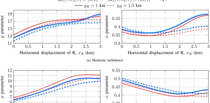
where E[ITnpe] = LSD + 2LRD. In order to validate the previous statement, the parameters αandµ are illustrated in
Fig. 3 as a function of the horizontal displacement of the relay node R when different relay locations yR={1,1.5} km are assumed. The depicted curves in Fig. 3 have been obtained by using a numerical approach due to the fact that finding the relation between α-µ and a-b parameters can be time-consuming and are technically difficult to perform. Note that the obtained results in Fig. 3 both α and µ when pointing errors are suppressed can be considered negligible as the ratio between the equivalent beam radius at the receiver and the pointing error displacement standard deviation at the receiver increases. Therefore, the expression in Eq. (23) can be sim-plified under the assumption that all links are affected by the same values of normalized beam width and normalized jitter as follows
DDF pe[dB]≈
20 ln(10)ln
1 +ϕ2
A0ϕ2
. (24)
The expression in Eq. (24) is the gain disadvantage corre-sponding to the direct transmission and, hence, this can be only used when the same values of normalized beam width and normalized jitter are assumed for each link. Moreover, it can be easily deduced that this gain disadvantage depends neither on the relay location nor on the atmospheric turbulence conditions asϕ2 increases. The expression in Eq. (24) can be
simplified even further as ϕ2→ ∞, obtaining an expression
only dependent on the value of normalized beam width, i.e.
0 0.5 1 1.5 2 2.5 3 11
13 15 17 19
Horizontal displacement of R,xR (km)
µ
parameter
(ωz/r, σs/r) = (5,1) (ωz/r, σs/r) = (10,1) npe
yR= 1km yR= 1.5 km
0 0.5 1 1.5 2 2.5 3 0.3
0.35 0.4 0.45
Horizontal displacement of R,xR (km)
α
parameter
(a) Moderate turbulence.
0 0.5 1 1.5 2 2.5 3 6
7 8 9 10 11 12
Horizontal displacement of R,xR (km)
µ
parameter
0 0.5 1 1.5 2 2.5 3 0.35
0.4 0.45 0.5 0.55
Horizontal displacement of R,xR (km)
α
parameter
(b) Strong turbulence.
A0. Hence, the gain disadvantage corresponding to the BDF
cooperative protocol can be accurately approximated by
DDF
pe[dB]≈ −
20 ln(A0)
ln(10) . (25)
The gain disadvantage, DDF
pe[dB], is depicted in Fig. 4 as a function of the ratio between ωz and σs. It can be observed that there is a perfect match between the exact results and obtained results for greater values of ωz/σs than 7 by using the approximate expression for the gain disadvantage of BDF relaying. According to the expres-sion in Eq. (25), it can be seen in Fig. 2 gain disadvantage of 22.3 and 34.07 dB when values of normalized beam width and normalized jitter of (ωz/r, σs/r) = (5,1) and
(ωz/r, σs/r) = (10,1)are considered, respectively.
5 7.5 10 12.5 15 17.5 20 22.5 25
10 20 30 40 50
ωz/σs
D
DF pe
[
d
B
]
Eq. (20) Eq. (22) Eq. (23) dSD= 3 km
(xR, yR) = (0.5,1)km
(xR, yR) = (1,1.5)km
Fig. 4. Gain disadvantage,DDF
pe[dB]for a source-destination
link distance ofdSD= 3km.
IV. CONCLUSION
The ergodic capacity of BDF cooperative protocol is ana-lyzed over gamma-gamma fading channels with pointing errors when line of sight is available. Novel closed-form approximate ergodic capacity expression is obtained in terms of the H-Fox function for a 3-way FSO communication system when the α-µ distribution to efficiently approximate the PDF of the sum of gamma-gamma with pointing errors variates is considered. Simple asymptotic expression at high SNR for the ergodic capacity of BDF cooperative protocol is obtained providing a perfect match between simulated and analytical results. It can be concluded that cooperative protocols such as BDF relaying are able to achieve a greater ergodic capacity than a direct transmission without cooperative communication. In addition, it is demonstrated that the ergodic capacity is strongly dependent on the relay location as well as pointing error effects. Apart from that, from the asymptotic ergodic capacity analysis can be concluded that the shift of the ergodic capacity versus SNR is more relevant than the slope of the curve in SNR compared to other performance metric such as BER and outage probability. Finally, the impact of the pointing errors on the ergodic capacity is deeply analyzed, which corroborates that the presence of pointing errors requires an increase in SNR in order to maintain the same performance in terms of capacity. This increase is related to the parameter A0.
ACKNOWLEDGMENT
The authors wish to acknowledge the financial support given by Spanish MINECO Project TEC2012-32606.
REFERENCES
[1] V. W. S. Chan, “Free-space optical communications,” J. Lightwave Technol., vol. 24, no. 12, pp. 4750–4762, 2006.
[2] L. Andrews, R. Phillips, and C. Hopen,Laser beam scintillation with applications. SPIE press, 2001, vol. 99.
[3] M. Karimi and M. Nasiri-Kenari, “BER analysis of cooperative systems in free-space optical networks,”J. Lightwave Technol., vol. 27, no. 24, pp. 5639 –5647, dec.15, 2009.
[4] A. Garcia-Zambrana, C. Castillo-Vazquez, B. Castillo-Vazquez, and R. Boluda-Ruiz, “Bit detect and forward relaying for FSO links using equal gain combining over gamma-gamma atmospheric turbulence channels with pointing errors,”Opt. Express, vol. 20, no. 15, pp. 16 394– 16 409, Jul 2012.
[5] K. P. Peppas, A. N. Stassinakis, H. E. Nistazakis, and G. S. Tombras, “Capacity analysis of dual amplify-and-forward relayed free-space optical communication systems over turbulence channels with pointing errors,” Journal of Optical Communications and Networking, vol. 5, no. 9, pp. 1032–1042, 2013.
[6] M. Aggarwal, P. Garg, and P. Puri, “Ergodic capacity of SIM based DF relayed optical wireless communication systems,”Photonics Technology Letters, IEEE, vol. 27, no. 10, pp. 1104–1107, 2015.
[7] ——, “Exact capacity of amplify-and-forward relayed optical wireless communication systems,”Photonics Technology Letters, IEEE, vol. 27, no. 8, pp. 903–906, 2015.
[8] H. E. Nistazakis, E. A. Karagianni, A. D. Tsigopoulos, M. E. Fafalios, and G. S. Tombras, “Average capacity of optical wireless commu-nication systems over atmospheric turbulence channels,” Journal of Lightwave Technology, vol. 27, no. 8, pp. 974–979, 2009.
[9] C. Liu, Y. Yao, Y. Sun, and X. Zhao, “Analysis of average capacity for free-space optical links with pointing errors over gamma-gamma turbulence channels,”Chinese Optics Letters, vol. 8, no. 6, pp. 537– 540, 2010.
[10] F. Benkhelifa, Z. Rezki, and M. Alouini, “Low SNR capacity of FSO links over gamma-gamma atmospheric turbulence channels,” Commu-nications Letters, IEEE, vol. 17, no. 6, pp. 1264–1267, June 2013. [11] I. Ansari, F. Yilmaz, and M. Alouini, “A unified performance of
free-space optical links over gamma-gamma turbulence channels with pointing errors,”submitted to IEEE Transactions on Communications, 2015.
[12] M. D. Yacoub, “Theα-µdistribution: A general fading distribution,” in
Proc. IEEE International Symposium on Personal, Indoor and Mobile Radio Communications, vol. 2, 2002, pp. 629–633.
[13] A. A. Farid and S. Hranilovic, “Outage capacity optimization for free-space optical links with pointing errors,”J. Lightwave Technol., vol. 25, no. 7, pp. 1702–1710, July 2007.
[14] H. G. Sandalidis, T. A. Tsiftsis, and G. K. Karagiannidis, “Optical wireless communications with heterodyne detection over turbulence channels with pointing errors,”J. Lightwave Technol., vol. 27, no. 20, pp. 4440–4445, 2009.
[15] I. S. Gradshteyn and I. M. Ryzhik, Table of integrals, series and products, 7th ed. Academic Press Inc., 2007.
[16] M. A. Al-Habash, L. C. Andrews, and R. L. Phillips, “Mathematical model for the irradiance probability density function of a laser beam propagating through turbulent media,”Opt. Eng., vol. 40, p. 8, 2001. [17] A. P. Prudnikov, Y. A. Brychkov, and O. I. Marichev, Integrals and
series Volume 3: More Special Functions. Gordon and Breach Science Publishers, 1999, vol. 3.
[18] Wolfram Research, Inc. The Wolfram functions site. [Online]. Available: http://functions.wolfram.com
[19] F. Yilmaz and M.-S. Alouini, “Product of the powers of generalized nakagami-m variates and performance of cascaded fading channels,” in Global Telecommunications Conference, 2009. GLOBECOM 2009. IEEE. IEEE, 2009, pp. 1–8.
[20] ——, “Novel asymptotic results on the high-order statistics of the chan-nel capacity over generalized fading chanchan-nels,” in Signal Processing Advances in Wireless Communications (SPAWC), 2012.

![Fig. 4. Gain disadvantage, D pe DF [dB] for a source-destination link distance of d SD = 3 km.](https://thumb-us.123doks.com/thumbv2/123dok_es/6394144.787597/6.918.79.439.344.526/fig-gain-disadvantage-df-source-destination-link-distance.webp)