DIPLOMADO DE PRODUNDIZACION CISCO PRUEBA DE HABILIDADES PRÁCTICAS CCNP
LUISA LILIAM TALERO DURAN
UNIVERSIDAD NACIONAL ABIERTA Y A DISTANCIA – UNAD
ESCUELA DE CIENCIAS BASICAS, TECNOLOGIA E INGENIERIA -ECBTI
INGENIERÍA DE TELECOMUNICACIONES
BOGOTA
DIPLOMADO DE PRODUNDIZACION CISCO PRUEBA DE HABILIDADES
PRÁCTICAS CCNP
LUISA LILIAM TALERO DURAN
DIRECTOR
INGENIERO GERARDO GRANADOS ACUÑA
UNIVERSIDAD NACIONAL ABIERTA Y A DISTANCIA – UNAD
ESCUELA DE CIENCIAS BASICAS, TECNOLOGIA E INGENIERIA -ECBTI
INGENIERÍA DE TELECOMUNICACIONES
BOGOTA
3
NOTA DE ACEPTACIÓN:
Presidente del Jurado
Jurado
Jurado
4
AGRADECIMIENTOS
5
TABLA DE CONTENIDO
LISTAS DE ILUSTRACIONES ... 6
LISTA DE TABLAS ... 9
GLOSARIO ... 10
RESUMEN ... 11
ABSTRACT ... 11
INTRODUCCIÓN ... 12
DESARROLLO ... 13
ESCENARIO 1 ... 13
DIRECCIONAMIENTO ... 14
ESCENARIO 2 ... 25
CONCLUSIONES ... 58
6
LISTAS DE ILUSTRACIONES
Ilustración 1- Escenario1 ... 13
Ilustración 2- Simulación de escenario 1 ... 13
Ilustración 3- Configuración interface Serial1/0 WAN ... 15
Ilustración 4- Configuración interface Fa0/0 LAN ... 15
Ilustración 5 Configuración interface Serial 1/0 WAN ... 16
Ilustración 6- Configuración interface Serial 1/1 WAN ... 17
Ilustración 7- Configuración interface Fa0/0 LAN ... 17
Ilustración 8- IConfiguración interface Serial 1/1 WAN ... 18
Ilustración 9- Configuración interface LAN ... 18
Ilustración 10- Enrutamiento WAN En Router Bucaramanga ... 19
Ilustración 11- Configuración Router Serial Interface1/1 Ipv6 OSPF R2-R3 ... 20
Ilustración 12- Configuración router interface 0/0 LAN OSPF area 1 ... 20
Ilustración 13- Configuración Stubby ... 20
Ilustración 14- Configuración ruta por defecto y protocolo ... 21
Ilustración 15- Configuración enrutamiento ... 22
Ilustración 16- Configuración enrutamiento ... 22
Ilustración 17- Creación lista de acceso ... 22
Ilustración 18- Anunciación de lista de acceso en EIGRP ... 22
Ilustración 19- Tabla de enrutamiento Router 1 ... 23
Ilustración 20- Tabla de enrutamiento Router 2 ... 23
Ilustración 21- Tabla de enrutamiento Router 3 ... 23
Ilustración 22- Ping R3 R1 ... 24
Ilustración 23- Ping R1 R3 ... 24
Ilustración 24- Traza R1R3 ... 24
Ilustración 25- Traza R3 R1 ... 24
7
Ilustración 27- Ping R1R2 ... 25
Ilustración 28- Ping R2 R3 ... 25
Ilustración 29- Ping R3R2 ... 25
Ilustración 30- Escenario 2 ... 26
Ilustración 31- Simulación Escenario 2 ... 26
Ilustración 32- Simulación Escenario 2 ... 27
Ilustración 33- Interfaces apagadas DSL2 ... 28
Ilustración 34- Interfaces apagadas ASL1 ... 29
Ilustración 35 Interfaces apagadas ASL2 ... 30
Ilustración 36- Interfaces apagadas ASL2 ... 30
Ilustración 37- Hostname DLS2 ... 31
Ilustración 38- Hostname ASL1 ... 31
Ilustración 39- Hostname ALS2 ... 31
Ilustración 40- Configuración de port-channel 12 hacia DSL2 ... 32
Ilustración 41- Configuración de port-channel 12 hacia DSL1 ... 32
Ilustración 42- Configuración de port-channel 12 hacia DSL1 ... 33
Ilustración 43- Configuración de port-channel 1... 34
Ilustración 44- Configuración de port-channel 2... 35
Ilustración 45- Configuración del port-channel 4 ... 36
Ilustración 46- Configuración del port-channel 3 ... 37
Ilustración 47- Configuración de port-channel 4... 38
Ilustración 48- Configuración de port-channel 4... 39
Ilustración 49- Configuración de interfaces troncales ... 40
Ilustración 50- Configuración de interfaces troncales ... 40
Ilustración 51- Configuración de interfaces troncales ... 41
Ilustración 52- Configuración de interfaces troncales ... 41
Ilustración 53- Configuración VTP DSL1 ... 42
Ilustración 54- Configuración VTP ASL1 ... 42
Ilustración 55- Configuración VTP ASL2 ... 43
8
Ilustración 57- Configuración de VLAN’s DLS2 ... 45
Ilustración 58- Configuración de VLAN’s ALS1 ... 46
Ilustración 59- Configuración de VLAN’s ALS2 ... 48
Ilustración 60- Configuración de VLAN’s DSL1... 49
Ilustración 61- Configuración de VLAN’s DSL1... 50
Ilustración 62- Suspensión de VLAN 434 ... 50
Ilustración 63- Suspensión de VLAN 567 ... 51
Ilustración 64- Configuración STP DSL1 ... 51
Ilustración 65- Configuración STP DSL2 ... 52
Ilustración 66- Configuración de VLAN’s DSL1... 53
Ilustración 67- Configuración de VLAN’s DSL2... 53
Ilustración 68- Configuración de VLAN’s ALS1 ... 53
Ilustración 69- Configuración de VLAN’s ALS2 ... 54
Ilustración 70- troncales DSL1 ... 54
Ilustración 71- Verificación configuraciones troncales DSL1 ... 55
Ilustración 72- Verificación configuraciones VLAN’s ALS1 ... 55
Ilustración 73- Verificación configuraciones VLAN’s ALS1 ... 56
Ilustración 74- Verificación Port-channels DSL1 ... 56
Ilustración 75- Verificación Port-channels DSL1 ... 57
Ilustración 76- Verificación Port-channels DSL1 ... 57
9
LISTA DE TABLAS
10
GLOSARIO
Routing Y Switching: El funcionamiento de una red consiste en conectar los ordenadores y periféricos utilizando dos tipos de equipos: routers y switches. Los routers y switches permiten a los dispositivos que están conectados a la red comunicarse unos con otros, así como con otras redes.
Networking: se basa en el establecimiento de una red profesional de contactos, que permite darnos a conocer, tanto a nivel personal como de empresa. También nos ayudará a conseguir posibles inversores o colaboradores. Es una de las prácticas más frecuentes dentro del ámbito empresarial y entre los emprendedores. Potocolos De Red: designa el conjunto de reglas que rigen el intercambio de información a través de una red de computadoras.
Vlan: (Red de área local virtual o LAN virtual) es una red de área local que agrupa
un conjunto de equipos de manera lógica y no física.
Efectivamente, la comunicación entre los diferentes equipos en una red de área local está regida por la arquitectura física. Gracias a las redes virtuales (VLAN), es posible liberarse de las limitaciones de la arquitectura física (limitaciones geográficas, limitaciones de dirección, etc.), ya que se define una segmentación lógica basada en el agrupamiento de equipos según determinados criterios (direcciones MAC, números de puertos, protocolos, etc.).
Lista de acceso: es un listado secuencial de condiciones de permiso o prohibición que se aplican a direcciones IP o a protocolos IP de capa superior. Las listas de acceso identifican tráfico que ha de ser filtrado en su transito por el router, pero no pueden filtrar ál trafico originado por el propio router.
EIGRP: EIGRP es utilizado en redes TCP/IP y de Interconexión de Sistemas Abierto (OSI) como un protocolo de enrutamiento del tipo vector distancia avanzado, propiedad de Cisco, que ofrece las mejores características de los algoritmos vector distancia y de estado de enlace.
11
RESUMEN
El presente trabajo contiene el desarrollo del laboratorio propuesto según la fase final del diplomado de profundización cisco CCNP en el cual se desarrollaron casuísticas en las cuales se presentan soluciones de implementación de red, entre estos los protocolos de enrutamientos EIGRP y OSPF, aplicando rutas estáticas y listas de acceso para filtrar rutas. Adicional se podrá evidenciar técnicas de enrutamiento en la cuales se implementa alta convergencia por medio de la redundancia dada. Y finalizando y no menos importante la implementación de solución a nivel de seguridad de red. A nivel de SW se puede evidenciar la implementación a nivel LAN con aplicaciones de políticas de seguridad tales como STP, validación y aplicación configuración de canal para puertos o segmentación del dominio de Broadcast a nivel de la capa 2, creación de interfaces virtuales (port-channel), con el fin de tener redes que lógicamente son independientes, aunque estas se encuentren dentro de una misma red física. De esta forma, un usuario podría disponer de varias VLANs.
Palabras clave: Listas de Acceso, Enrrutamiento, Protocolo, Redundancia, Interface.
ABSTRACT
This paper contains the development of the proposed laboratory according to the final phase of the Cisco CCNP deepening diploma in which case studies were developed in which network implementation solutions are presented, among them the EIGRP and OSPF routing protocols, applying statistical routes and access lists to filter routes. Additional routing techniques may be evidenced in any high convergence implementation through the given redundancy. And finalizing and not least the implementation of network security solution level. At the SW level, implementation at LAN level can be evidenced with security policy applications such as STP, channel configuration validation and application for ports or Broadcast domain segmentation at layer 2 level, creation of virtual interfaces (port - channel), create networks that are logically independent, although these are within the same physical network. In this way, a user could have several VLANs.
12
INTRODUCCIÓN
13
DESARROLLO
ESCENARIO 1
Ilustración 1- Escenario1
14
DIRECCIONAMIENTO
Tabla 1 Direccionamiento
BOGOTA
INTERFACE IP MASCARA
Fa0/0 192.168.110.1 24
Se1/0 192.168.9.1 30
Fa0/0 2001:DB8:ACAD:110::1 64
Se1/0 2001:DB8:ACAD:B::1 64
BUCARAMANGA
INTERFACE IP MASCARA
Fa0/0 192.168.2.1 24
Se1/0 192.168.9.2 30
Se1/1 192.168.9.5 30
Fa0/0 2001:DB8:ACAD:110::B 64
Se1/0 2001:DB8:ACAD:B::2 64
Se1/1 2001:DB8:ACAD:91::1 64
MEDELLIN
INTERFACE IP MASCARA
Se1/1 192.168.9.6 30
Fa0/0 192.168.3.1 24
Se1/1 2001:DB8:ACAD:91::2 64
Fa0/0 2001:DB8:ACAD:C::1 64
1. Configurar las interfaces con las direcciones IPv4 e Ipv6 que se muestran en la topología de red.
2. Topología de red. 2. Ajustar el ancho de banda a 128 kbps sobre cada uno de los enlaces seriales ubicados en R1, R2,
Se ejecuta la configuración sobre los router R1,R2 y R3
BOGOTA(config)#ipv6 unicast-routing Habilitar Ipv6
BOGOTA(config)# int se1/0 interface serial
BOGOTA(config-if)# ip address 192.168.9.1 255.255.255.252 definición dirección Ipv4
BOGOTA(config-if)#no shutdown subir interface
BOGOTA(config-if)#description WAN TO BUCARAMANGA se define descripción
15
BOGOTA(config-if)#bandwidth 128 se define el ancho de banda
BOGOTA(config-if)#clock rate 128000 Se conIIustración velocidad de reloj para DCE
BOGOTA(config-if)#exit Salir
BOGOTA(config)#inter FastEthernet0/0 ingresar a interface LAN
BOGOTA(config-if)#ip address 192.168.110.1 255.255.255.0 se define dirección Ipv4
BOGOTA(config-if)#ipv6 address 2001:DB8:ACAD:110::1/64 se define dirección Ipv6
BOGOTA(config-if)#description LAN BOGOTA se conIIustración descripción a la interface
BOGOTA(config-if)#no shutdown Subir interface
Ilustración 3- Configuración interface Serial1/0 WAN
Ilustración 4- Configuración interface Fa0/0 LAN
BUCARAMANGA(config)#ipv6 unicast-routing Habilitar Ipv6
16
BUCARAMANGA(config-if)#description WAN TO BOGOTA se agrega descripción
BUCARAMANGA(config-if)#ip address 192.168.9.2 255.255.255.252 se define dirección Ipv4
BUCARAMANGA(config-if)#bandwidth 128 se conIIustración ancho de banda
BUCARAMANGA(config-if)#ipv6 address 2001:DB8:ACAD:B::2/64 se define dirección Ipv6
BUCARAMANGA(config-if)#no shutdown Subir interface
BUCARAMANGA(config-if)#exit Salir de la interface
BUCARAMANGA(config)#inter FastEthernet0/0 ingresar a interface LAN
BUCARAMANGA(config-if)#ip address 192.168.2.1 255.255.255.0 se define dirección Ipv4
BUCARAMANGA(config-if)#ipv6 address 2001:DB8:ACAD:110::B/64 se define dirección Ipv6
BUCARAMANGA(config-if)#DEScription LAN BUCARAMANGA se
conIIustración descripción a la interface
BUCARAMANGA(config-if)#no shu Subir interface
BUCARAMANGA(config-if)#exit Salir de la interface
BUCARAMANGA(config)#interface serial 1/1 ingresar a interface serial
BUCARAMANGA(config-if)#description WAN TO MEDELLIN se agrega descripción
BUCARAMANGA(config-if)#ip address 192.168.9.5 255.255.255.252 se define dirección Ipv4
BUCARAMANGA(config-if)#no shutdown Subir interface
BUCARAMANGA(config-if)#bandwidth 128 se conIIustración ancho de banda
BUCARAMANGA(config-if)#clock rate 128000 Se define velocidad de reloj para DCE
17
Ilustración 6- Configuración interface Serial 1/1 WAN
Ilustración 7- Configuración interface Fa0/0 LAN
MEDELLIN(config)#ipv6 unicast-routing Habilitar Ipv6
MEDELLIN(config)#interface serial 1/1 ingresar a interface serial
MEDELLIN(config-if)#ip address 192.168.9.6 255.255.255.252 se define dirección Ipv4
MEDELLIN(config-if)#description WAN TO BUCARAMANGA se agrega
descripción
MEDELLIN(config-if)#ipv6 add 2001:DB8:ACAD:91::2/64 se define dirección Ipv6
MEDELLIN(config-if)#no shutdown Subir interface
MEDELLIN(config)#interface FastEthernet0/0 ingresar a interface LAN
MEDELLIN(config-if)#ip address 192.168.3.1 255.255.255.0 se define dirección Ipv4
MEDELLIN(config-if)#ipv6 address 2001:DB8:ACAD:C::1/64 se define dirección Ipv6
MEDELLIN(config-if)#description LAN TO MEDELLIN se agrega descripción
18
Ilustración 8- IConfiguración interface Serial 1/1 WAN
Ilustración 9- Configuración interface LAN
3. En R2 y R3 configurar las familias de direcciones OSPFv3 para Ipv4 e Ipv6. Utilice el identificador de enrutamiento 2.2.2.2 en R2 y 3.3.3.3 en R3 para ambas familias de direcciones.
4. En R2, configurar la interfaz F0/0 en el área 1 de OSPF y la conexión serial entre R2 y R3 en OSPF área 0.
5. En R3, configurar la interfaz F0/0 y la conexión serial entre R2 y R3 en OSPF área 0.
BUCARAMANGA(config)#ipv6 router eigrp 101 Se define proceso eigrp para Ipv6
BUCARAMANGA(config-rtr)#eigrp router-id 2.0.0.0 se define el ID de proceso eigrp
BUCARAMANGA(config-rtr)#redistribute connected se redistribuyen rutas directamente conectada
BUCARAMANGA(config-if)#exit Salir
BUCARAMANGA(config)#ipv6 router ospf 200 Se define proceso para OSPF en Ipv6
BUCARAMANGA(config-rtr)#router-id 2.2.2.2 se define identificador
BUCARAMANGA(config-router)#exit Salir
19
BUCARAMANGA(config-if)#ipv6 enable se habilita Ipv6 en la interface
BUCARAMANGA(config-if)#ipv6 ospf 200 area 0 se conIIustración el enrutamiento y el area para la interface
BUCARAMANGA(config)#interface FastEthernet0/0 ingresar a interface LAN
BUCARAMANGA(config-if)#ipv6 enable se habilita Ipv6 en la interface
BUCARAMANGA(config-if)#ipv6 ospf 200 area 1 se conIIustración enrutamiento y area
BUCARAMANGA(config)#router ospf 200 Se define proceso OSPF
BUCARAMANGA(config-router)#redistribute eigrp 101 subnets se redistribuyen subredes en el proceso eigrp
BUCARAMANGA(config-router)#exit Salir
BUCARAMANGA(config)#router eigrp 101 ingresar a proceso de eigrp
BUCARAMANGA(config-router)#redistribute ospf 200 se redistribuye proceso OSPF 200
BUCARAMANGA(config)#router ospf 200 ingresar a proceso OSPF
BUCARAMANGA(config-router)#router-id 2.2.2.2 se define identificador
BUCARAMANGA(config-router)#network 192.168.9.4 0.0.0.3 area 0 se anuncia red WAN
BUCARAMANGA(config-router)#network 192.168.2.0 0.0.0.255 area 1
se anuncia red LAN con area 1
20
Ilustración 11- Configuración Router Serial Interface1/1 Ipv6 OSPF R2-R3
Ilustración 12- Configuración router interface 0/0 LAN OSPF area 1
6. Configurar el área 1 como un área totalmente Stubby.
7. Propagar rutas por defecto de Ipv4 y Ipv6 en R3 al interior del dominio OSPFv3. Nota: Es importante tener en cuenta que una ruta por defecto es diferente a la definición de rutas estáticas.
BUCARAMANGA(config)#router ospf 200 ingresar a proceso OSPF 200
BUCARAMANGA(config-router)# area 2 stub se conIIustración area 2 como stubby
Ilustración 13- Configuración Stubby
MEDELLIN(config)#router ospf 200 ingresar a proceso OSPF 200
MEDELLIN(config-router)#default-information origínate se propaga la ruta por defecto sobre toda el proceso OSPF
21
MEDELLIN(config)#ip route 0.0.0.0 0.0.0.0 192.168.3.2 se define ruta por defecto
MEDELLIN(config-if)#ipv6 ospf 200 area 0 ingresar a proceso OSPF en Ipv6
MEDELLIN(config-rtr)#default-information origínate se propaga la ruta por defecto sobre toda el proceso OSPF
MEDELLIN(config)#ipv6 route ::/0 2001:DB8:ACAD:C::2 se define ruta por defecto
Ilustración 14- Configuración ruta por defecto y protocolo
8. Realizar la configuración del protocolo EIGRP para Ipv4 como Ipv6. Configurar la interfaz F0/0 de R1 y la conexión entre R1 y R2 para EIGRP con el sistema autónomo 101. Asegúrese de que el resumen automático está desactivado.
9. Configurar las interfaces pasivas para EIGRP según sea apropiado. 10. En R2, configurar la redistribución mutua entre OSPF y EIGRP
BOGOTA(config)#router eigrp 101 Se define proceso EIGRP
BOGOTA(config-router)#network 192.168.110.0 se anuncia red LAN
BOGOTA(config-router)#network 192.168.9.0 0.0.0.3 se anuncia red WAN
BOGOTA(config-router)#no auto-summary se configurano sumarizar la redes
BOGOTA(config-rtr)#eigrp router-id 1.0.0.0 se define identificador
BOGOTA(config-router)#exit
22
BOGOTA(config)#interface se1/0 ingresar a interface WAN
BOGOTA(config-if)#ipv6 eigrp 101 Se define proceso EIGRP para Ipv6
BOGOTA(config)#inter FastEthernet0/0 ingresar a interface LAN
BOGOTA(config-if)#ipv6 eigrp 101 Se define proceso EIGRP para Ipv6
Ilustración 15- Configuración enrutamiento
Ilustración 16- Configuración enrutamiento
11. En R2, de hacer publicidad de la ruta 192.168.3.0/24 a R1 mediante una lista de distribución y ACL.
BUCARAMANGA(config)#access-list 10 permit 192.168.3.0 0.0.0.255
creación lista de acceso agregando la red a anunciar
BUCARAMANGA(config)#router eigrp 101 ingresar a proceso EIGRP
BUCARAMANGA(config-router)#distribute-list 10 out distribuir la lista de acceso en el enrutamiento EIGRP
Ilustración 17- Creación lista de acceso
23
Parte 2: Verificar conectividad de red y control de la trayectoria.
Registrar las tablas de enrutamiento en cada uno de los routers, acorde a los parámetros de configuración establecidos en el escenario propuesto.
Ilustración 19- Tabla de enrutamiento Router 1
Ilustración 20- Tabla de enrutamiento Router 2
Ilustración 21- Tabla de enrutamiento Router 3
24
Ilustración 22- Ping R3 R1
Ilustración 23- Ping R1 R3
Ilustración 24- Traza R1R3
25
Ilustración 26- Ping R2R1
Ilustración 27- Ping R1R2
Ilustración 28- Ping R2 R3
Ilustración 29- Ping R3R2
26
Ilustración 30- Escenario 2
Ilustración 31- Simulación Escenario 2
Parte 1: Configurar la red de acuerdo con las especificaciones.
27
Ilustración 32- Simulación Escenario 2
DSL1(config)#interface range ethernet 1/2-3 se define el rango de interfaces
DSL1(config-if-range)# shut Bajar interface administrativamente
DSL1(config-if-range)#interface range ethernet 2/0-3 se define el rango de interfaces
DSL1(config-if-range)# shut Bajar interface administrativamente
DSL1(config-if-range)#interface range ethernet 3/0-2 se define el rango de interfaces
28
Ilustración 33- Interfaces apagadas DSL2
DSL2(config)#interface range ethernet 1/2-3 se define el rango de interfaces
DSL2(config-if-range)# shut Bajar interface administrativamente
DSL2(config-if-range)#interface range ethernet 2/0-3 se define el rango de interfaces
DSL2(config-if-range)# shut Bajar interface administrativamente
DSL2(config-if-range)#interface range ethernet 3/0-2 se define el rango de interfaces
29
Ilustración 34- Interfaces apagadas ASL1
ALS1(config)#interface range ethernet 1/2-3 se define el rango de interfaces
ALS1(config-if-range)# shut Bajar interface administrativamente ALS1(config-if-range)#interface range ethernet 2/0-3
ALS1(config-if-range)# shut Bajar interface administrativamente
ALS1(config-if-range)#interface range ethernet 3/0-2 se define el rango de interfaces
30
Ilustración 35 Interfaces apagadas ASL2
ALS2(config)#interface range ethernet 1/2-3 se define el rango de interfaces
ALS2(config-if-range)# shut Bajar interface administrativamente
ALS2(config-if-range)#interface range ethernet 2/0-3 se define el rango de interfaces
ALS2(config-if-range)# shut Bajar interface administrativamente
ALS2(config-if-range)#interface range ethernet 3/0-2 se define el rango de interfaces
ALS2(config-if-range)# shut Bajar interface administrativamente
B. Asignar un nombre a cada switch acorde al escenario establecido
31
DSL1(config)#hostname DSL1 Cambio de hostname
Ilustración 37- Hostname DLS2
DSL2(config)#hostname DSL2 Cambio de hostname
Ilustración 38- Hostname ASL1
ALS1(config)#hostname ALS1 Cambio de hostname
Ilustración 39- Hostname ALS2
ALS2(config)#hostname ALS2 Cambio de hostname
b. Configurar los puertos troncales y Port-channels tal como se muestra en el diagrama.
32
Ilustración 40- Configuración de port-channel 12 hacia DSL2
DSL1(config)#interface range eth0/1-2 se define el rango de interfaces
DSL1(config-if-range)# channel-group 12 mode active asociación al port-channel con su respectivo protocolo
DSL1(config-if-range)# int Port-channel12 ingresar al port-channel
DSL1(config-if)#switchport trunk encapsulation dot1q se realiaza troncalización con encapsulamiento dot1q
DSL1(config-if)#switchport trunk native vlan 800 se agrega vlan Nativa 800
DSL1(config-if)#switchport mode trunk define puerto en modo troncal
DSL1(config-if)#no shut Suben interfaces
Ilustración 41- Configuración de port-channel 12 hacia DSL1
DSL1(config)#vlan 100 creación de vlan 4094
DSL1(config)#name WAN TO DLS1 TO DLS2 se agrega descripción DSL1(config)#interface vlan 100 creación interface capa 3
33
NOTA: Subira capa 3 debido a que la versión del IOS del Sw no permite configurar port-channel capa 3
Ilustración 42- Configuración de port-channel 12 hacia DSL1
DSL2(config)#interface range eth0/1-2 se define el rango de interfaces DSL2(config-if-range)# channel-group 12 mode active asociación al port-channel con su respectivo protocolo
DSL2(config-if-range)# int Port-channel12 ingresar al port-channel
DSL2(config-if)#switchport trunk encapsulation dot1q se realiaza troncalización con encapsulamiento dot1q
DSL2(config-if)#switchport trunk native vlan 800 se agrega vlan Nativa 800
DSL2(config-if)#switchport mode trunk define puerto en modo troncal DSL2(config-if)#no shut Suben interfaces
34
Ilustración 43- Configuración de port-channel 1
DSL1(config)#interface range Et0/2-3
DSL1(config-if-range)#channel-group 1 mode active se asocia port-channel 1
DSL1(config-if-range)# int Port-channel1 ingresar al port-channel
DSL1(config-if)#switchport trunk encapsulation dot1q se realiaza troncalización con encapsulamiento dot1q
DSL1(config-if)#switchport trunk native vlan 800 se agrega vlan Nativa 800
35
Ilustración 44- Configuración de port-channel 2
DSL2(config)#interface range Et0/2-3 se define el rango de interfaces DSL2(config-if-range)#channel-group 2 mode active se asocia port-channel
DSL2(config-if-range)# int Port-channel1 ingresar al port-channel
DSL2(config-if)#switchport trunk encapsulation dot1q se realiaza troncalización con encapsulamiento dot1q
DSL2(config-if)#switchport trunk native vlan 800 se agrega vlan Nativa 800
DSL2(config-if)#switchport mode trunk define puerto en modo troncal DSL2(config-if)#no shut Suben interfaces
36
Ilustración 45- Configuración del port-channel 4
DSL1(config)#interface range Et1/0-1 se define el rango de interfaces DSL1(config-if-range)#channel-group 2 mode active se asocia port-channel y protocolo
DSL1(config-if-range)# int Port-channel1 ingresar al port-channel
DSL1(config-if)#switchport trunk encapsulation dot1q se realiaza troncalización con encapsulamiento dot1q
DSL1(config-if)#switchport trunk native vlan 800 se agrega vlan Nativa 800
37
Ilustración 46- Configuración del port-channel 3
ALS1(config)#interface range Et1/0-1 se define el rango de interfaces ALS1(config-if-range)#channel-group 3 mode active se asocia port-channel y protocolo
ALS1(config-if-range)# int Port-channel1 ingresar al port-channel
ALS1(config-if)#switchport trunk encapsulation dot1q se realiaza troncalización con encapsulamiento dot1q
ALS1(config-if)#switchport trunk native vlan 800 se agrega vlan Nativa 800
38
Ilustración 47- Configuración de port-channel 4
DLS2(config)#interface range Et1/0-1 se define el rango de interfaces DLS2(config-if-range)#channel-group 3 mode active se asocia port-channel y protocolo
DLS2(config-if-range)# int Port-channel1 ingresar al port-channel
DLS2(config-if)#switchport trunk encapsulation dot1q se realiaza troncalización con encapsulamiento dot1q
DLS2(config-if)#switchport trunk native vlan 800 se agrega vlan Nativa 800
39
Ilustración 48- Configuración de port-channel 4
ALS2(config)#interface range Et1/0-1 se define el rango de interfaces ALS2(config-if-range)#channel-group 4 mode active se asocia port-channel y protocolo
ALS2(config-if-range)# int Port-channel1 ingresar al port-channel
ALS2(config-if)#switchport trunk encapsulation dot1q se realiaza troncalización con encapsulamiento dot1q
ALS2(config-if)#switchport trunk native vlan 800 se agrega vlan Nativa 800
ALS2(config-if)#switchport mode trunk define puerto en modo troncal ALS2(config-if)#no shut Suben interfaces
Todos los puertos troncales serán asignados a la VLAN 800 como la VLAN nativa.
40
Ilustración 49- Configuración de interfaces troncales
41
Ilustración 51- Configuración de interfaces troncales
Ilustración 52- Configuración de interfaces troncales
D. Configurar DLS1, ALS1, y ALS2 para utilizar VTP versión 3
Utilizar el nombre de dominio UNAD con la contraseña cisco123
Configurar DLS1 como servidor principal para las VLAN
42
Ilustración 53- Configuración VTP DSL1
DSL1(config)#vtp domain UNAD se establece domino vtp
DSL1(config)#vtp password cisco123 ingresar password para vtp DSL1(config)#vtp version 3 se define version del vtp
DSL1(config)#vtp mode server se establece rol del sw para el vtp
Ilustración 54- Configuración VTP ASL1
ALS1(config)#vtp domain UNAD se establece domino vtp
ALS1(config)#vtp password cisco123 ingresar password para vtp ALS1(config)#vtp version 3 se define version del vtp
43
Ilustración 55- Configuración VTP ASL2
ALS2(config)#vtp domain UNAD se establece domino vtp
ALS2(config)#vtp password cisco123 ingresar password para vtp ALS2(config)#vtp version 3 se define version del vtp
ALS2(config)#vtp mode client se establece rol del sw para el vtp
E. Configurar en el servidor principal las siguientes:
Tabla 2 Vlan´s
NUMERO DE VLAN NOMBRE DE VLAN
800 Nativa
12 Ejecutivos
234 Huespedes
1111 Videonet
434 Estacionamiento
123 Mantenimiento
1010 Voz
44
Ilustración 56- Configuración de VLAN’s DLS1
DSL1(config)#vlan 12 creación de vlan en database DSL1(config-vlan)#name EJECUTIVOS se tag el nombre DSL1(config)#vlan 123 creación de vlan en database
DSL1(config-vlan)#name MANTENIMIENTO se tag el nombre DSL1(config)#vlan 234 creación de vlan en database
DSL1(config-vlan)#name HUESPEDES se tag el nombre DSL1(config)#vlan 434 creación de vlan en database
DSL1(config-vlan)#name ESTACIONAMIENTO se tag el nombre DSL1(config)#vlan 800 creación de vlan en database
DSL1(config-vlan)#name NATIVA se tag el nombre DSL1(config)#vlan 1010 creación de vlan en database DSL1(config-vlan)#name VOZ se tag el nombre
DSL1(config)#vlan 1111 creación de vlan en database DSL1(config-vlan)#name VIDEONET se tag el nombre DSL1(config)#vlan 3456 creación de vlan en database
45
Ilustración 57- Configuración de VLAN’s DLS2
DSL2(config)#vlan 12 creación de vlan en database DSL2(config-vlan)#name EJECUTIVOS se tag el nombre DSL2(config)#vlan 123 creación de vlan en database
DSL2(config-vlan)#name MANTENIMIENTO se tag el nombre DSL2(config)#vlan 234 creación de vlan en database
46
DSL2(config-vlan)#name ESTACIONAMIENTO se tag el nombre DSL2(config)#vlan 800 creación de vlan en database
DSL2(config-vlan)#name NATIVA se tag el nombre DSL2(config)#vlan 1010 creación de vlan en database DSL2(config-vlan)#name VOZ se tag el nombre
DSL2(config)#vlan 1111 creación de vlan en database DSL2(config-vlan)#name VIDEONET se tag el nombre DSL2(config)#vlan 3456 creación de vlan en database
DSL2(config-vlan)#name ADMINISTRACION se tag el nombre
47
ALS1(config)#vlan 12 creación de vlan en database ALS1 (config-vlan)#name EJECUTIVOS se tag el nombre ALS1 (config)#vlan 123 creación de vlan en database
ALS1 (config-vlan)#name MANTENIMIENTO se tag el nombre ALS1 (config)#vlan 234 creación de vlan en database
ALS1 (config-vlan)#name HUESPEDES se tag el nombre ALS1 (config)#vlan 434 creación de vlan en database
ALS1 (config-vlan)#name ESTACIONAMIENTO se tag el nombre ALS1 (config)#vlan 800 creación de vlan en database
ALS1 (config-vlan)#name NATIVA se tag el nombre ALS1 (config)#vlan 1010 creación de vlan en database ALS1 (config-vlan)#name VOZ se tag el nombre
ALS1 (config)#vlan 1111 creación de vlan en database ALS1 (config-vlan)#name VIDEONET se tag el nombre ALS1 (config)#vlan 3456 creación de vlan en database
48
Ilustración 59- Configuración de VLAN’s ALS2
ALS2(config)#vlan 12 creación de vlan en database ALS2 (config-vlan)#name EJECUTIVOS se tag el nombre ALS2 (config)#vlan 123 creación de vlan en database
ALS2 (config-vlan)#name MANTENIMIENTO se tag el nombre ALS2 (config)#vlan 234 creación de vlan en database
ALS2 (config-vlan)#name HUESPEDES se tag el nombre ALS2 (config)#vlan 434 creación de vlan en database
ALS2 (config-vlan)#name ESTACIONAMIENTO se tag el nombre ALS2 (config)#vlan 800 creación de vlan en database
ALS2 (config-vlan)#name NATIVA se tag el nombre ALS2 (config)#vlan 1010 creación de vlan en database ALS2 (config-vlan)#name VOZ se tag el nombre
ALS2 (config)#vlan 1111 creación de vlan en database ALS2 (config-vlan)#name VIDEONET se tag el nombre ALS2 (config)#vlan 3456 creación de vlan en database
49
F. En DLS1, suspender la VLAN 434
Ilustración 60- Configuración de VLAN’s DSL1
DSL1(config)#vlan 434 ingresar a la VLAN
DSL1(config-vlan)#state suspend VLAN en estado suspendido
50
Ilustración 61- Configuración de VLAN’s DSL1
DSL2(config)#vtp password cisco123 ingresar password para vtp DSL2(config)#vtp version 2 se define version del vtp
DSL2(config)#vtp mode transperent se establece rol del sw para el vtp
H. Suspender VLAN 434 en DLS2
Ilustración 62- Suspensión de VLAN 434
DSL2(config)#vlan 434 ingresar a la VLAN
DSL2(config-vlan)#state suspend VLAN en estado suspendido
51
Ilustración 63- Suspensión de VLAN 567
DSL2(config)#vlan 567 creación de vlan
DSL2(config-vlan)#name CONTABILIDAD se agrega tag
Configurar DLS1 como spannig-tree root para las VLAN 1, 12, 434, 800, 1010, 1111 y 3456 y como raíz secundaria para las VLAN 123 y 234.
Ilustración 64- Configuración STP DSL1
DSL1(config)#spanning-tree vlan 1 priority 8192 se establece la prioridad a VLAN
DSL1(config)#spanning-tree vlan 12 priority 8192 se establece la prioridad a VLAN
DSL1(config)#spanning-tree vlan 100 priority 8192 se establece la prioridad a VLAN
DSL1(config)#spanning-tree vlan 434 priority 8192 se establece la prioridad a VLAN
DSL1(config)#spanning-tree vlan 800 priority 8192 se establece la prioridad a VLAN
DSL1(config)#spanning-tree vlan 1010 priority 8192 se establece la prioridad a VLAN
DSL1(config)#spanning-tree vlan 1111 priority 8192 se establece la prioridad a VLAN
DSL1(config)#spanning-tree vlan 3456 priority 8192 se establece la prioridad a VLAN
52
DSL1(config)#spanning-tree vlan 234 priority 16384 se establece la prioridad a VLAN
Configurar DLS2 como Spanning tree root para las VLAN 123 y 234 y como una raíz secundaria para las VLAN 12, 434, 800, 1010, 1111 y 3456.
Ilustración 65- Configuración STP DSL2
DSL2(config)#spanning-tree vlan 123 priority 8192 se establece la prioridad a VLAN
DSL2(config)#spanning-tree vlan 234 priority 8192 se establece la prioridad a VLAN
Configurar las siguientes interfaces como puertos de acceso, asignado las VLAN de la siguiente manera:
Tabla 3 Puertos de Acceso
INTERFACE DSL1 DLS2 ALS1 ALS2
INT F0/6 3456 12 ,1010 12, 1010 234
INT F0/15 1111 1111 1111 1111
53
Ilustración 66- Configuración de VLAN’s DSL1
Ilustración 67- Configuración de VLAN’s DSL2
54
Ilustración 69- Configuración de VLAN’s ALS2
Parte 2: conectividad de red de prueba y las opciones configuradas.
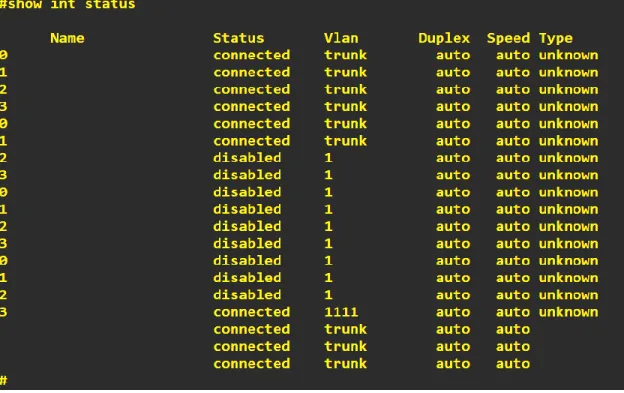
A. Verificar la existencia de las VLAN correctas en todos los switches y la asignación de puertos troncales y acceso
55
Ilustración 71- Verificación configuraciones troncales DSL1
56
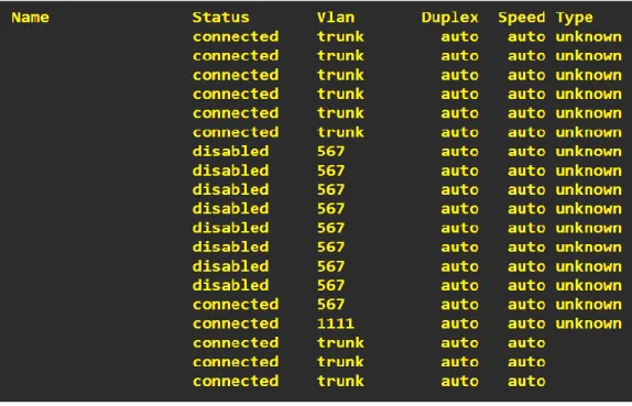
Ilustración 73- Verificación configuraciones VLAN’s ALS1
A. Verificar que el Etherchannel entre DLS1 y ALS1 está configurado correctamente
57
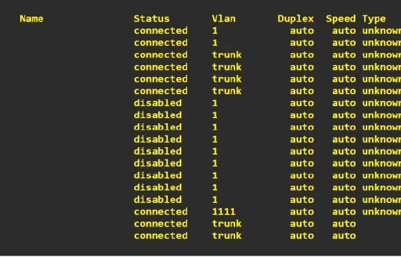
Ilustración 75- Verificación Port-channels DSL1
A. Verificar la configuración de spanning-tree entre DLS 1 o DLS2 para cada VLAN
Ilustración 76- Verificación Port-channels DSL1
58
CONCLUSIONES
Durante el estudio de los temas abarcados en el DIPLOMADO DE PROFUNDIZACION CISCO CCNP y con la ejecución de diferentes configuraciones a nivel red, profundización y entendimiento de los protocolos a nivel de tamaños de red LAN, MAN o WAN, lo que nos permitió conocer el diseño y las posibles implementaciones de forma estructural y completa para cada uno de los casos tanto a nivel routing and switching.
Durante el desarrollo de cada una de las practicas a lo largo del curso validamos la integralidad entre protocolos desarrollados y la solución a cada uno de los escenarios propuestos.
Mediante la configuración de esquemas de conmutación a nivel de Switches y mediante la implementación de protocolos basados VLANs a nivel de capa 2 al interior de una red jerárquica convergente
59
BIBLIOGRAFIA
CISCO (2008). Document How Virtual Private Networks Work Recuperado de https://www.cisco.com/c/en/us/support/docs/security-vpn/ipsec-negotiation-ike-protocols/14106-how-vpn-works.html
CISCO (2007). Configuring IP Access Lists Document ID:23602 Recuperado de https://www.cisco.com/c/en/us/support/docs/security/ios-firewall/23602-confaccesslists.html
CISCO (2019). Retrieved 10 December 2019, from Recuperado de
https://www.cisco.com/c/es_mx/support/docs/lan-switching/etherchannel/12033-89.pdf
CISCO (2012). Redistributing Routing Protocols Recuperado de https://www.cisco.com/c/en/us/support/docs/ip/enhanced-interior-gateway-routing-protocol-eigrp/8606-redist.html
Gonzalez, Luis. El Blog de Luis Gonzalez. (2019). Configuración de
EtherChannel Recuperado de
http://lgonzalez.blogdiario.com/1305759671/configuraci-n-de-etherchannel/
Support, T., Routing, I., & Paper, T. (2019). OSPF Design Guide. Retrieved
10 December 2019, from
https://www.cisco.com/c/en/us/support/docs/ip/open-shortest-path-first-ospf/7039-1.html
Support, T., Routing, I., & TechNotes, T. (2019). Redistributing Routing
Protocols. Retrieved 10 December 2019, from