DIPLOMADO DE PROFUNDIZACIÓN CISCO PRUEBA DE HABILIDADES PRACTICAS CCNP
JHONN MAURICIO BAUTISTA SALÓN
UNIVERSIDAD NACIONAL ABIERTA Y A DISTANCIA UNAD
ESCUELA DE CIENCIAS BÁSICAS, TECNOLOGÍA E INGENIERÍA – ECBTI INGENIERÍA EN TELECOMUNICACIONES
DIPLOMADO DE PROFUNDIZACIÓN CISCO PRUEBA DE HABILIDADES PRACTICAS CCNP
JHONN MAURICIO BAUTISTA SALÓN
Diplomado de opción de grado presentado para poder optar el titulo De INGENIERO EN TELECOMUNICACIONES
DIRECTOR
MSc. GERARDO GRANADOS ACUÑA
UNIVERSIDAD NACIONAL ABIERTA Y A DISTANCIA UNAD
ESCUELA DE CIENCIAS BÁSICAS, TECNOLOGÍA E INGENIERÍA – ECBTI INGENIERÍA EN TELECOMUNICACIONES
3
NOTA DE ACEPTACIÓN _____________________ _____________________ _____________________ _____________________ _____________________ _____________________ _____________________
_____________________
firma del presidente del jurado
_____________________ firma del jurado
_____________________ firma del jurado
4
AGRADECIMIENTOS
Primero que todo agradecerle al Dios todo poderoso, que por medio de nuestro
señor Jesucristo, intercedió en mí, me dio cada esa capacidad y cada uno de sus
dones para poder lograr este objetivo. También a mi familia esposa e hijos, que con
un su paciencia pudieron entenderme en esos momentos en que dejaba de
compartir con ellos para dedicarme a temas relacionados con el estudio. A mis
padres, que en ciertos momentos fueron ese apoyo económico y palabras de fuerza
que me daban para poder sacar este objetivo adelante. A la empresa donde laboro
actualmente, a la universidad UNAD, a los profesores de cada uno de los cursos
que siempre están atentos a apoyar al estudiante en lo que requiera. A todas
aquellas personas que de una o cierta forma me apoyaron para poder conseguir el
5
CONTENIDO
AGRADECIMIENTOS………...4
CONTENIDO………...….5
LISTA DE TABLAS………...6
LISTA DE FIGURAS………...….7-8 RESUMEN………....9
ABSTRACT………..………..10
INTRODUCCIÓN……….………..11
DESARROLLO………...12
1. ESCENARIO 1………...……12
2. ESCENARIO 2………...………30
CONCLUSIONES………..………84
6
LISTA DE TABLAS
Tabla 1. Información de Vlans a configurar………...56
7
LISTA DE FIGURAS
Figura 1. Topología de la red propuesta………12
Figura 2. Topología de la red desarrollada………13
Figura 3. Tabla de red de R1………...26
Figura 4. Tabla de red de R2………...27
Figura 5. Tabla de red de R3………...28
Figura 6. Ping de R1 a R2………29
Figura 7. Ping de R2 a R1………29
Figura 8. Ping de R3 a serial 0/1/0 de R2………..29
Figura 9. Topología de red propuesta………31
Figura 10. Topologia de red desarrollada………..32
Figura 11. Vlans correspondientes a DLS1………...71
Figura 12. Vlans correspondientes a DLS2………...72
Figura 13. Vlans correspondientes a ALS1………...73
Figura 14. Vlans correspondientes a ALS2………...74
Figura 15. Interfaces con IP asignada DLS1……….75
Figura 16. Interfaces con IP asignada DLS2……….76
Figura 17. Interfaces con IP asignada ALS1……….77
Figura 18. Interfaces con IP asignada ALS2……….78
8
Figura 20. Estado de EtherChannel DLS2………80
Figura 21. Estado del Spanning tree de DLS1……….81
Figura 22. Estado del Spanning tree de DLS1……….82
9 RESUMEN
La evaluación denominada “Prueba de habilidades prácticas”, forma parte de las
actividades evaluativas del Diplomado de Profundización CCNA, la cual busca
identificar el grado de desarrollo de competencias y habilidades que fueron
adquiridas a lo largo del diplomado y a través de la cual se pondrá a prueba los
niveles de comprensión y solución de problemas relacionados con diversos
aspectos de Networking. La prueba de habilidades podrá ser desarrollada en el
Laboratorio SmartLab o mediante el uso de herramientas de Simulación (Puede ser
Packet Tracer o GNS3). Para esta actividad, el estudiante dispone de cerca de dos
semanas para realizar las tareas asignadas en cada uno de los escenarios
propuestos, acompañado de los respectivos procesos de documentación de la
solución, correspondientes al registro de la configuración de cada uno de los
dispositivos, la descripción detallada del paso a paso de cada una de las etapas
realizadas durante su desarrollo, el registro de los procesos de verificación de
conectividad mediante el uso de comandos ping, traceroute, show ip route, entre
otros.
10 ABSTRACT
The evaluation called "Practical skills test" is part of the evaluation activities of the
CCNA Deepening Diploma, which seeks identify the degree of development of skills
and abilities that were acquired throughout the diploma and through which the levels
of understanding and solution of problems related to various Networking aspects.
The skills test may be developed in the SmartLab Laboratory or by using Simulation
tools (It can be Packet Tracer or GNS3). For this activity, the student has about two
weeks to perform the tasks assigned in each of the proposed scenarios,
accompanied by the respective documentation processes of the solution,
corresponding to the registration of the configuration of each of the devices, the
Detailed description of the step by step of each of the stages carried out during its
development, the registration of the connectivity verification processes through the
use of ping, traceroute, show ip route commands, among others.
11
INTRODUCCIÓN
La evaluación prueba de habilidades prácticas es una actividad final del diplomado de
profundización de Cisco CCNP, con el fin de determinar lo aprendido durante el desarrollo
del diplomado. En este documento se evidencia dos laboratorios, el primero tratamos
Routing y el segundo de Switch buscando justipreciar el nivel de habilidades adquiridas
durante el titulado donde se puso en práctica configuraciones básicas para los dispositivos
activos según la topología planteada en cada escenario (configuración de nombre de los
equipos, conexiones físicas, protocolo interconexión de red basada en internet versión 4 y
versión 6) también trabajamos protocolos como Ethernet, OSPF, EIGRP, VTP, IP SLA,
entre otros temas. Encontrará el paso a paso de los respectivos procesos de la solución,
perteneciente al registro de la configuración de cada uno de los dispositivos, con la
12
DESARROLLO
1. ESCENARIO 1
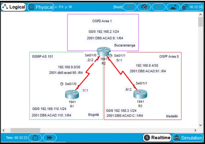
Una empresa de confecciones posee tres sucursales distribuidas en las ciudades
de Bogotá, Medellín y Bucaramanga, en donde el estudiante será el administrador
de la red, el cual deberá configurar e interconectar entre sí cada uno de los
dispositivos que forman parte del escenario, acorde con los lineamientos
establecidos para el direccionamiento IP, protocolos de enrutamiento y demás
aspectos que forman parte de la topología de red.
Topología de red
13
figura 2. Topología de red desarrollada
Parte 0: Configurar nombre dispositivo y deshabilitar búsqueda DNS
R1:
Router>enable Pasar de Modo Usuario a Modo
Privilegiado
14
Enter configuration commands, one per line. End with CNTL/Z.
Router(config)#hostname R1 Nombre Router
R1(config)#no ip domain-lookup Deshabilitar Busqueda de DNS
R2:
Router>enable Pasar de Modo Usuario a Modo
Privilegiado
Router#conf terminal Ir a configuración global
Enter configuration commands, one per line. End with CNTL/Z.
Router(config)#hostname R2 Nombre Router
R2(config)#no ip domain-lookup Deshabilitar Busqueda de DNS
R3:
Router>enable Pasar de Modo Usuario a Modo
Privilegiado
Router#conf terminal Ir a configuración global
Enter configuration commands, one per line. End with CNTL/Z.
Router(config)#hostname R3 Nombre Router
15
Parte 1: Configuración del escenario propuesto
1. Configurar las interfaces con las direcciones IPv4 e IPv6 que se muestran en la topología de red.
R1:
R1(config)#interface serial 0/1/0 Ingresamos a la interface S0/1/0 R1(config-if)#ipv6 address 2001:db8:acad:90::1/64 Asignamos dirección IPV6
R1(config-if)#ip address 192.168.9.1 255.255.255.252 Asignamos dirección IPV4
R1(config-if)#no shutdown Activamos interface
%LINK-5-CHANGED: Interface Serial0/1/0, changed state to down
R1(config-if)#interface GigabitEthernet0/0 Ingresamos a la interface G0/0
R1(config-if)#ipv6 address 2001:db8:acad:110::1/64 Asignamos dirección IPV6 R1(config-if)#ip address 192.168.110.1 255.255.255.0 Asignamos dirección IPV4
R1(config-if)#no shutdown Activamos interface
16
R2(config)#interface serial 0/1/0 Ingresamos a la interface S0/1/0 R2(config-if)#ipv6 address 2001:db8:acad:90::2/64 Asignamos dirección IPV6
R2(config-if)#ip address 192.168.9.2 255.255.255.252 Asignamos dirección IPV4
R2(config-if)#no shutdown Activamos interface
R2(config-if)#interface GigabitEthernet0/0 Ingresamos a la interface G0/0
R2(config-if)#ipv6 address 2001:db8:acad:b::1/64 Asignamos dirección IPV6
R2(config-if)#ip address 192.168.2.1 255.255.255.0 Asignamos dirección IPV4
R2(config-if)#no shutdown Activamos interface
R2(config-if)#interface serial 0/1/1 Ingresamos a la interface S0/1/1
R2(config-if)#ipv6 address 2001:db8:acad:91::1/64 Asignamos dirección IPV6
17
R2(config-if)#no shutdown Activamos interface
%LINK-5-CHANGED: Interface Serial0/1/0, changed state to up
%LINK-5-CHANGED: Interface GigabitEthernet0/0, changed state to up
!
R2#
%SYS-5-CONFIG_I: Configured from console by console
%LINEPROTO-5-UPDOWN: Line protocol on Interface Serial0/1/0, changed state
to up
R3:
R3(config)#interface serial 0/1/1 Ingresamos a la interface S0/1/1 R3(config-if)#ipv6 address 2001:db8:acad:91::2/64 Asignamos dirección IPV6
R3(config-if)#ip address 192.168.9.6 255.255.255.252 Asignamos dirección IPV4
R3(config-if)#no shutdown Activamos interface
%LINK-5-CHANGED: Interface Serial0/1/1, changed state to down
18
R3(config-if)#ipv6 address 2001:db8:acad:c::1/64 Asignamos dirección IPV6
R3(config-if)#ip address 192.168.3.1 255.255.255.0 Asignamos dirección IPV4
R3(config-if)#no shutdown Activamos interface
R3(config-if)#
%LINK-5-CHANGED: Interface GigabitEthernet0/0, changed state to up
2. Ajustar el ancho de banda a 128 kbps sobre cada uno de los enlaces seriales ubicados en R1, R2, y R3 y ajustar la velocidad de reloj de las conexiones de DCE
según sea apropiado.
R1:
R1(config)#interface serial 0/1/0 Ingresamos a la interface S0/1/0 R1(config-if)#clock rate 64000 Configuramos reloj interface DCE
R1(config-if)#bandwidth 128 Configuramos ancho de banda
R2:
R2(config)#interface serial 0/1/0 Ingresamos a la interface S0/1/0
R2(config-if)#bandwidth 128 Configuramos ancho de banda
R2(config-if)#interface serial 0/1/1 Ingresamos a la interface S0/1/1
R2(config-if)#bandwidth 128 Configuramos ancho de banda
19 R3:
R3(config-if)#interface serial 0/1/1 Ingresamos a la interface S0/1/1
R3(config-if)#bandwidth 128 Configuramos ancho de banda
3. En R2 y R3 configurar las familias de direcciones OSPFv3 para IPv4 e IPv6. Utilice el identificador de enrutamiento 2.2.2.2 en R2 y 3.3.3.3 en R3 para ambas
familias de direcciones.
4. En R2, configurar la interfaz F0/0 en el área 1 de OSPF y la conexión serial entre R2 y R3 en OSPF área 0.
5. En R3, configurar la interfaz F0/0 y la conexión serial entre R2 y R3 en OSPF área 0.
R2:
R2(config)#router ospf 1 Ingresamos configuración ospf 1 ipv4
20 R2(config-router)#exit
R2(config)#ipv6 unicast-routing Habilitamos IPV6 en el router
R2(config)#ipv6 router ospf 1 Ingresamos configuración ospf 1 ipv6
R2(config-rtr)#router-id 2.2.2.2 Configuramos el ID de enrutamiento
R2(config-rtr)#ex
R2(config)#int g0/0 Ingresamos a la interface
G0/0
R2(config-if)#ipv6 ospf 1 a 1 Asignamos la interface a
Ospf 1 IPV6
R2(config-if)#no sh
R2(config)#int s 0/1/1 Ingresamos a la interface serial 0/1/1
R2(config-if)#ipv6 ospf 1 a 0 Asignamos la interface a
Ospf 1 IPV6
R2(config-if)#no sh
R3:
21
R3(config-router)#network 192.168.3.0 0.0.0.255 a 0 Añadimos la red 192.168.3.0 R3(config-router)#network 192.168.9.4 0.0.0.3 a 0 Añadimos la red 192.168.9.4
00:55:11: %OSPF-5-ADJCHG: Process 1, Nbr 192.168.9.5 on Serial0/1/1 from
LOADING to FULL, Loading Done
R3(config)#ipv6 unicast-routing Habilitamos IPV6 en el router
R3(config)#ipv6 router ospf 1 Ingresamos configuración ospf 1 ipv6
R3(config-rtr)#router-id 3.3.3.3 Configuramos el ID de enrutamiento
R3(config-rtr)#exi
R3(config)#int g0/0 Ingresamos a la interface
G0/0
R3(config-if)#ipv6 ospf 1 a 0 Asignamos la interface a
Ospf 1 IPV6
R3(config)#int s 0/1/1 Ingresamos a la interface serial 0/1/1
R3(config-if)#ipv6 ospf 1 a 0 Asignamos la interface a
22
00:56:35: %OSPFv3-5-ADJCHG: Process 1, Nbr 2.2.2.2 on Serial0/1/1 from
LOADING to FULL, Loading Done
6. Configurar el área 1 como un área totalmente Stubby.
R2(config)#router ospf 1 Ingresamos configuración ospf 1 ipv4
R2(config-router)#area 1 stub no-summary Área 1 como un área totalmente Stubby
7. Propagar rutas por defecto de IPv4 y IPv6 en R3 al interior del dominio OSPFv3. Nota: Es importante tener en cuenta que una ruta por defecto es diferente a la definición de rutas estáticas.
R3(config)#ipv6 route ::/0 2001:DB8:ACAD:91:: Ruta por
defecto
R3(config)#ipv6 router ospf 1 Ingresamos configuración ospf 1 ipv6
23
8. Realizar la configuración del protocolo EIGRP para IPv4 como IPv6. Configurar la interfaz F0/0 de R1 y la conexión entre R1 y R2 para EIGRP con el sistema
autónomo 101. Asegúrese de que el resumen automático está desactivado.
R1(config)#router eigrp 101 Ingresamos configuración
Eigrp 101
R1(config-router)#network 192.168.110.0 Añadimos la red
192.168.110.0
R1(config-router)#network 192.168.9.0 Añadimos la red 192.168.9.0 R1(config-router)#no auto-summary Desactivamos el resumen automático
R2(config)#router eigrp 101 Ingresamos configuración
Eigrp 101
R2(config-router)#network 192.168.2.0 Añadimos la red 192.168.2.0 R2(config-router)#network 192.168.9.0 Añadimos la red 192.168.9.0 R2(config-router)#
%DUAL-5-NBRCHANGE: IP-EIGRP 101: Neighbor 192.168.9.1 (Serial0/1/0) is up:
new adjacency
24
9. Configurar las interfaces pasivas para EIGRP según sea apropiado.
R1(config)#router eigrp 101 Ingresamos configuración
Eigrp 101
R1(config-router)#passive-interface se 0/1/0 Interface pasiva s0/1/0 R1(config-router)#passive-interface g0/0 Interface pasiva g0/0 R1(config-router)#
%DUAL-5-NBRCHANGE: IP-EIGRP 101: Neighbor 192.168.9.2 (Serial0/1/0) is
down: holding time expired
10. En R2, configurar la redistribución mutua entre OSPF y EIGRP para IPv4 e IPv6. Asignar métricas apropiadas cuando sea necesario.
R2(config)#router ospf 1
R2(config-router)#redistribute eigrp 101 subnets Redistribuimos EIGRP IPV4
R2(config-router)#ex
R2(config)#router eigrp 101
R2(config-router)# redistribute ospf 1 metric 155 300 110 1 250 Redistribuimos OSPF IPV4
25
R2(config-rtr)#redistribute eigrp 101 metric 155 Redistribuimos EIGRP IPV6
R2(config-rtr)#exit
R2(config)#ipv6 router eigrp 101
R2(config-rtr)#redistribute ospf 1 metric 256 10000 255 1 1500 Redistribuimos OSPF IPV6
11. En R2, de hacer publicidad de la ruta 192.168.3.0/24 a R1 mediante una lista de distribución y ACL.
R2(config)#access-list 1 permit 192.168.3.0 0.0.0.255 Creamos la ACL 1 permitiendo la ruta 192.168.3.0
Parte 2: Verificar conectividad de red y control de la trayectoria.
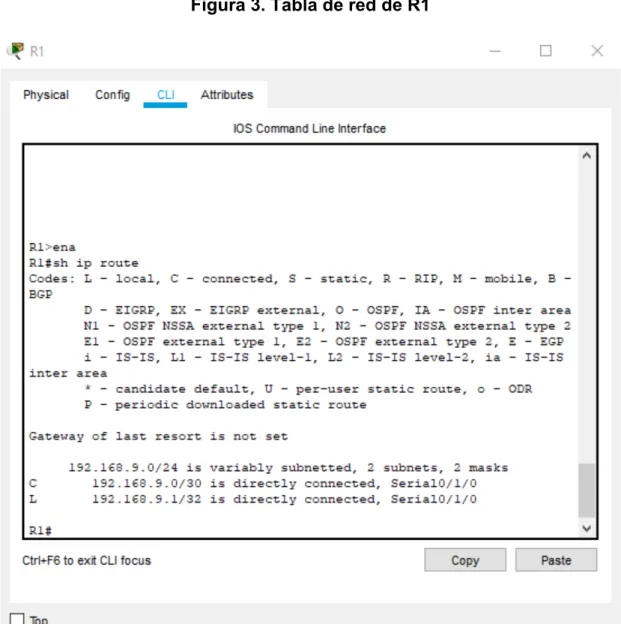
a. Registrar las tablas de enrutamiento en cada uno de los routers, acorde con
26
27
28
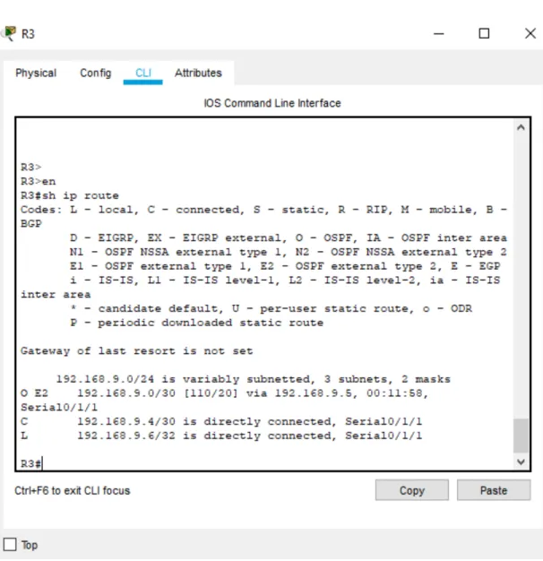
Figura 5. Tabla de red de R3
29
Figura 6. Ping de R1 a R2
Figura 7. Ping de R2 a R1
30
c. Verificar que las rutas filtradas no están presentes en las tablas de enrutamiento
de los routers correctas.
Nota: Puede ser que Una o más direcciones no serán accesibles desde todos los routers después de la configuración final debido a la utilización de listas de
distribución para filtrar rutas y el uso de IPv4 e IPv6 en la misma red.
2. ESCENARIO 2
Una empresa de comunicaciones presenta una estructura Core acorde a la
topología de red, en donde el estudiante será el administrador de la red, el cual
deberá configurar e interconectar entre sí cada uno de los dispositivos que forman
parte del escenario, acorde con los lineamientos establecidos para el
direccionamiento IP, etherchannels, VLANs y demás aspectos que forman parte del
escenario propuesto.
31
32
Figura 10. Topologia de red desarrollada
Parte 1: Configurar la red de acuerdo con las especificaciones.
33
Aplicamos los siguientes comandos en cada Switch.
Switch>enabl Pasar de Modo Usuario a Modo
Privilegiado
Switch#conf t Ir a configuración global
Enter configuration commands, one per line. End with CNTL/Z.
Switch(config)#interfa range fa0/1-24 Ingresamos al rango de interface 1-24 Switch(config-if-range)#shutdown Apagamos las interfaces
%LINK-5-CHANGED: Interface FastEthernet0/1, changed state to administratively
down
%LINK-5-CHANGED: Interface FastEthernet0/2, changed state to administratively
down
%LINK-5-CHANGED: Interface FastEthernet0/3, changed state to administratively
down
%LINK-5-CHANGED: Interface FastEthernet0/4, changed state to administratively
34
%LINK-5-CHANGED: Interface FastEthernet0/5, changed state to administratively
down
b. Asignar un nombre a cada switch acorde al escenario establecido.
ALS1:
Switch(config)#hostname ALS1 Asignamos nombre al Switch ALS1
ALS1(config)#no ip domain-lookup Deshabilitar Búsqueda de DNS
ALS1(config)#
ALS2:
Switch(config)#hostname ALS2 Asignamos nombre al Switch ALS2
ALS2(config)#no ip domain-lookup Deshabilitar Búsqueda de DNS
35 DLS1:
Switch(config)#hostname DLS1 Asignamos nombre al Switch DLS1
DLS1(config)#no ip domain-lookup Deshabilitar Búsqueda de DNS
DLS1(config)#
DLS2:
Switch(config)#hostname DLS2 Asignamos nombre al Switch DLS2
DLS2(config)#no ip domain-lookup Deshabilitar Búsqueda de DNS
DLS2(config)#
36
1) La conexión entre DLS1 y DLS2 será un EtherChannel capa-3 utilizando LACP.
Para DLS1 se utilizará la dirección IP 10.12.12.1/30 y para DLS2 utilizará
10.12.12.2/30.
DLS1(config)#interfa range fa0/11-12 Ingresamos al rango de interfaces DLS1(config-if-range)#channel-protocol lacp Configuramos el Protocolo de control de agregación de enlaces LACP
DLS1(config-if-range)#channel-group 12 mode active Activamos la agrupación lógica de los enlaces físicos DLS1(config-if-range)#
Creating a port-channel interface Port-channel 12
DLS1(config-if-range)#no shut Activamos las interfaces
%LINK-5-CHANGED: Interface FastEthernet0/11, changed state to down
%LINK-5-CHANGED: Interface FastEthernet0/12, changed state to down
DLS1(config-if-range)#exit
37
DLS1(config-if)#no switchport Desactivamos switchport para poder asignar una dirección ip
DLS1(config-if)#ip add 10.12.12.1 255.255.255.252 Asignamos una Ip 10.12.12.1
DLS2:
DLS2(config)#inter range fast0/11-12 Ingresamos al rango de interfaces DLS2(config-if-range)#channel-protocol lacp Configuramos el Protocolo de
control de agregación de enlaces LACP
DLS2(config-if-range)#channel-group 12 mode active Activamos la agrupación lógica de los enlaces físicos DLS2(config-if-range)#
Creating a port-channel interface Port-channel 12
DLS2(config-if-range)#no shu Activamos interface
DLS2(config-if-range)#
38
%LINEPROTO-5-UPDOWN: Line protocol on Interface FastEthernet0/11, changed
state to up
%LINK-5-CHANGED: Interface FastEthernet0/12, changed state to up
%LINEPROTO-5-UPDOWN: Line protocol on Interface FastEthernet0/12, changed
state to up
%LINK-5-CHANGED: Interface Port-channel1, changed state to up
%LINEPROTO-5-UPDOWN: Line protocol on Interface Port-channel1, changed
state to up
DLS2(config-if-range)#exit
DLS2(config)#inter port-channel 12 Ingresamos a la interface port-channel
DLS2(config-if)#no switchport Desactivamos switchport para poder asignar una dirección ip
DLS2(config-if)#
%LINEPROTO-5-UPDOWN: Line protocol on Interface Port-channel1, changed
39
%LINEPROTO-5-UPDOWN: Line protocol on Interface Port-channel1, changed
state to up
DLS2(config-if)#ip add 10.12.12.2 255.255.255.252 Asignamos una Ip 10.12.12.2
2) Los Port-channels en las interfaces Fa0/7 y Fa0/8 utilizarán LACP.
DLS1:
DLS1(config)#inter ran fa0/7-8 Ingresamos al rango de interfaces DLS1(config-if-range)#channel-protocol lacp Configuramos el Protocolo de
control de agregación de enlaces LACP
DLS1(config-if-range)#channel-group 1 mode active Activamos la agrupación lógica de los enlaces físicos
DLS1(config-if-range)#no shut Activamos interfaces
Creating a port-channel interface Port-channel 1
40
%LINK-5-CHANGED: Interface FastEthernet0/8, changed state to down
DLS1(config-if-range)#exit
DLS1(config)#interface port-channel 1 Ingresamos interface port-channel
DLS1(config-if)#no shut Activamos interface port-channel
DLS1(config-if)#sw trunk encap dot1q Configuración de encapsulación trunk
DLS1(config-if)#sw mode trunk Enlace modo trunk DLS1(config-if)#exit
ALS1:
ALS1(config)#inter ran fa0/7-8 Ingresamos al rango de interfaces ALS1(config-if-range)#channel-protocol lacp Configuramos el Protocolo de
control de agregación de enlaces LACP
ALS1(config-if-range)#channel-group 1 mode active Activamos la agrupación lógica de los enlaces físicos ALS1(config-if-range)#
Creating a port-channel interface Port-channel 1
41 ALS1(config-if-range)#
%LINK-5-CHANGED: Interface FastEthernet0/7, changed state to up
%LINEPROTO-5-UPDOWN: Line protocol on Interface FastEthernet0/7, changed
state to up
%LINK-5-CHANGED: Interface FastEthernet0/8, changed state to up
%LINEPROTO-5-UPDOWN: Line protocol on Interface FastEthernet0/8, changed
state to up
%LINEPROTO-5-UPDOWN: Line protocol on Interface FastEthernet0/7, changed
state to down
%LINEPROTO-5-UPDOWN: Line protocol on Interface FastEthernet0/7, changed
state to up
%LINEPROTO-5-UPDOWN: Line protocol on Interface FastEthernet0/8, changed
state to down
%LINEPROTO-5-UPDOWN: Line protocol on Interface FastEthernet0/8, changed
state to up
%LINK-5-CHANGED: Interface Port-channel1, changed state to up
%LINEPROTO-5-UPDOWN: Line protocol on Interface Port-channel1, changed
state to up
42
ALS1(config)#interface port-channel 1 Ingresamos interface port-channel
ALS1(config-if)#no sh Activamos interface
ALS1(config-if)#sw mode trunk Interface modo trunk ALS1(config-if)#
DLS2:
DLS2(config)#inter ran fa0/7-8 Ingresamos al rango de interfaces DLS2(config-if-range)#channel-protocol lacp Configuramos el Protocolo de
control de agregación de enlaces LACP
DLS2(config-if-range)#channel-group 2 mode active Activamos la agrupación lógica de los enlaces físicos DLS2(config-if-range)#
Creating a port-channel interface Port-channel 2
DLS2(config-if-range)#no sh Activamos interfaces
43
%LINK-5-CHANGED: Interface FastEthernet0/8, changed state to down
DLS2(config-if-range)#exit
DLS2(config)#interf port-channel 2 Ingresamos interface port-channel
DLS2(config-if)#no sh
DLS2(config-if)#sw trunk encap dot1q Configuración de encapsulación trunk
DLS2(config-if)#sw mode trunk Modo trunk DLS2(config-if)#exit
DLS2(config)#
ALS2:
ALS2(config)#inter ra fa0/7-8 Ingresamos al rango de interfaces ALS2(config-if-range)#channel-protocol lacp Configuramos el Protocolo de
control de agregación de enlaces LACP
ALS2(config-if-range)#channel-group 2 mode active Activamos la agrupación lógica de los enlaces físicos ALS2(config-if-range)#
44
ALS2(config-if-range)#no shut Activamos interfaces
ALS2(config-if-range)#
%LINK-5-CHANGED: Interface FastEthernet0/7, changed state to up
%LINEPROTO-5-UPDOWN: Line protocol on Interface FastEthernet0/7, changed
state to up
%LINK-5-CHANGED: Interface FastEthernet0/8, changed state to up
%LINEPROTO-5-UPDOWN: Line protocol on Interface FastEthernet0/8, changed
state to up
%LINEPROTO-5-UPDOWN: Line protocol on Interface FastEthernet0/7, changed
state to down
%LINEPROTO-5-UPDOWN: Line protocol on Interface FastEthernet0/7, changed
state to up
45
%LINEPROTO-5-UPDOWN: Line protocol on Interface Port-channel2, changed
state to up
ALS2(config-if-range)#exit
ALS2(config)#interface port-channel 2 Ingresamos interface port-channel
ALS2(config-if)#no shut Activamos interface
ALS2(config-if)#sw mode trunk Interface modo trunk
3) Los Port-channels en las interfaces F0/9 y fa0/10 utilizará PAgP.
DLS1:
DLS1(config)#interfa ran fa0/9-10 Ingresamos al rango de interfaces
DLS1(config-if-range)#channel-protocol pagp Configuramos el Protocolo de agregación de puerto.
46 DLS1(config-if-range)#
Creating a port-channel interface Port-channel 4
DLS1(config-if-range)#no sh
%LINK-5-CHANGED: Interface FastEthernet0/9, changed state to down
%LINK-5-CHANGED: Interface FastEthernet0/10, changed state to down
DLS1(config-if-range)#inter port-channel 4 Ingresamos interface port-channel
DLS1(config-if)#sw trunk encapsulation dot1q Configuración de encapsulación trunk
DLS1(config-if)#sw mod trunk Interface modo trunk DLS1(config-if)#
ALS2:
ALS2(config)#inter ra fa0/9-10 Ingresamos al rango de interfaces ALS2(config-if-range)#channel-protocol pagp Configuramos el Protocolo de
47
ALS2(config-if-range)#channel-group 4 mode auto Modo Auto la agrupación lógica de los enlaces físicos ALS2(config-if-range)#
Creating a port-channel interface Port-channel 4
ALS2(config-if-range)#no shu Activamos interfaces
ALS2(config-if-range)#
%LINK-5-CHANGED: Interface FastEthernet0/9, changed state to up
%LINEPROTO-5-UPDOWN: Line protocol on Interface FastEthernet0/9, changed
state to up
%LINK-5-CHANGED: Interface FastEthernet0/10, changed state to up
%LINEPROTO-5-UPDOWN: Line protocol on Interface FastEthernet0/10, changed
state to up
%LINEPROTO-5-UPDOWN: Line protocol on Interface FastEthernet0/10, changed
48
%LINEPROTO-5-UPDOWN: Line protocol on Interface FastEthernet0/10, changed
state to up
%LINK-5-CHANGED: Interface Port-channel4, changed state to up
%LINEPROTO-5-UPDOWN: Line protocol on Interface Port-channel4, changed
state to up
%LINEPROTO-5-UPDOWN: Line protocol on Interface FastEthernet0/9, changed
state to down
%LINEPROTO-5-UPDOWN: Line protocol on Interface FastEthernet0/9, changed
state to up
%SPANTREE-2-RECV_PVID_ERR: Received 802.1Q BPDU on non trunk
Port-channel4 VLAN1.
%SPANTREE-2-BLOCK_PVID_LOCAL: Blocking Port-channel4 on VLAN0001.
Inconsistent port type.
49
ALS2(config)#inter port-channel 4 Ingresamos interface port-channel
ALS2(config-if)#sw mode trunk Interface modo trunk
ALS2(config-if)#%SPANTREE-2-UNBLOCK_CONSIST_PORT: Unblocking
Port-channel4 on VLAN0001. Port consistency restored.
%SPANTREE-2-UNBLOCK_CONSIST_PORT: Unblocking Port-channel4 on
VLAN0001. Port consistency restored.
DLS2:
DLS2(config)#interfa ra fa0/9-10 Ingresamos al rango de interfaces DLS2(config-if-range)#channel-protocol pagp Configuramos el Protocolo de
agregación de puerto.
DLS2(config-if-range)#channel-group 3 mode desira Modo deseable la agrupación lógica de los enlaces físicos
DLS2(config-if-range)#
50 DLS2(config-if-range)#no shut
%LINK-5-CHANGED: Interface FastEthernet0/9, changed state to down
%LINK-5-CHANGED: Interface FastEthernet0/10, changed state to down
DLS2(config-if-range)#ex
DLS2(config)#inter port-channel 3 Ingresamos interface port-channel
DLS2(config-if)#sw trunk encap dot1q Configuración de encapsulación trunk
DLS2(config-if)#sw mode trunk Interface modo trunk DLS2(config-if)#exit
DLS2(config)#
ASL1:
ALS1(config)#inter ra fa0/9-10 Ingresamos al rango de interfaces ALS1(config-if-range)#channel-protocol pagp Configuramos el Protocolo de
agregación de puerto.
51 ALS1(config-if-range)#
Creating a port-channel interface Port-channel 3
ALS1(config-if-range)#no shu Activamos interfaces
ALS1(config-if-range)#
%LINK-5-CHANGED: Interface FastEthernet0/9, changed state to up
%LINEPROTO-5-UPDOWN: Line protocol on Interface FastEthernet0/9, changed
state to up
%LINK-5-CHANGED: Interface FastEthernet0/10, changed state to up
%LINEPROTO-5-UPDOWN: Line protocol on Interface FastEthernet0/10, changed
state to up
%LINEPROTO-5-UPDOWN: Line protocol on Interface FastEthernet0/10, changed
52
%LINEPROTO-5-UPDOWN: Line protocol on Interface FastEthernet0/10, changed
state to up
%LINK-5-CHANGED: Interface Port-channel3, changed state to up
%LINEPROTO-5-UPDOWN: Line protocol on Interface Port-channel3, changed
state to up
ALS1(config-if-range)#exit
ALS1(config)#inter port-channel 3 Ingresamos interface port-channel
ALS1(config-if)#sw mode trunk Interface modo trunk ALS1(config-if)#ex
ALS1(config)#
4) Todos los puertos troncales serán asignados a la VLAN 800 como la VLAN nativa.
DLS1:
53
DLS1(config-if-range)#sw trunk native vlan 800 Configuración Vlan Nativa 800
DLS1(config-if-range)#
DLS2:
DLS2(config)#interface ra fa0/7-12 Ingresamos al rango de interfaces
DLS2(config-if-range)#sw trunk native vlan 800 Configuración Vlan Nativa 800
ASL1:
ALS1(config)#interface ra fa0/7-12 Ingresamos al rango de interfaces
ALS1(config-if-range)#sw trunk native vlan 800 Configuración Vlan Nativa 800
54
ALS2(config)#interface ra fa0/7-12 Ingresamos al rango de interfaces
ALS2(config-if-range)#sw trunk native vlan 800 Configuración Vlan Nativa 800
d. Configurar DLS1, ALS1, y ALS2 para utilizar VTP versión 3
1) Utilizar el nombre de dominio UNAD con la contraseña cisco123
2) Configurar DLS1 como servidor principal para las VLAN.
3) Configurar ALS1 y ALS2 como clientes VTP.
DLS1:
DLS1(config)#vtp domain UNAD Configuración VTP dominio UNAD Changing VTP domain name from NULL to UNAD
DLS1(config)#vtp password cisco123 Configuración VTP contraseña cisco123 Setting device VLAN database password to cisco123
55 DLS1(config)#
ASL1:
ALS1(config)#vtp domain UNAD Configuración VTP dominio UNAD Domain name already set to UNAD.
ALS1(config)#vtp password cisco123 Configuración VTP contraseña cisco123 Setting device VLAN database password to cisco123
ALS1(config)#vtp mode CLIENT Configuración VTP modo Client Setting device to VTP CLIENT mode.
ALS1(config)#
ASL2:
ALS2(config)#vtp domain UNAD Configuración VTP dominio UNAD Domain name already set to UNAD.
ALS2(config)#vtp password cisco123 Configuración VTP contraseña cisco123 Setting device VLAN database password to cisco123
ALS2(config)#vtp mode CLIENT Configuración VTP modo Client Setting device to VTP CLIENT mode.
56
e. Configurar en el servidor principal las siguientes VLAN: Tabla 1. Información de Vlans a configurar
DLS1(config)#vlan 800 Creación VLAN 800
DLS1(config-vlan)#name NATIVA Asignación de nombre a la
vlan
DLS1(config-vlan)#EXIT
DLS1(config)#vlan 12 Creación VLAN 12
DLS1(config-vlan)#name EJECUTIVOS Asignación de nombre a la vlan DLS1(config-vlan)#EXIT
DLS1(config)#vlan 234 Creación VLAN 234
DLS1(config-vlan)#name HUESPEDES Asignación de nombre a la vlan DLS1(config-vlan)#EXIT
DLS1(config)#vlan 434 Creación VLAN 434
57 DLS1(config-vlan)#exit
DLS1(config)#vlan 123 Creación VLAN 123
DLS1(config-vlan)#Name MANTENIMIENTO Asignación de nombre a la vlan DLS1(config-vlan)#EXIT
DLS1(config)#vlan 1010 Creación VLAN 1010
VLAN_CREATE_FAIL: Failed to create VLANs 1010 : extended VLAN(s) not
allowed in current VTP mode
DLS1(config)#exit
DLS1#conf t
Enter configuration commands, one per line. End with CNTL/Z.
DLS1(config)#vlan 1111 Creación VLAN 1111
VLAN_CREATE_FAIL: Failed to create VLANs 1111 : extended VLAN(s) not
allowed in current VTP mode
DLS1(config)#vlan 3456 Creación VLAN 3456
VLAN_CREATE_FAIL: Failed to create VLANs 3456 : extended VLAN(s) not
allowed in current VTP mode
DLS1(config)#
Nota:
Las VLAN extendidas no es posible su creación pues el Switch debe estar VTP
58 f. En DLS1, suspender la VLAN 434.
DLS1(config)#vlan 434 Ingresamos Vlan 434
DLS1(config-vlan)#state suspend Cambiar estado activo a
suspendido ^
% Invalid input detected at '^' marker.
DLS1(config-vlan)#
El comando state suspend no lo reconoce packet tracert versión 7.2.2
g. Configurar DLS2 en modo VTP transparente VTP utilizando VTP versión 2, y configurar en DLS2 las mismas VLAN que en DLS1.
DLS2(config)#vtp domain UNAD Configuración VTP dominio UNAD Domain name already set to UNAD.
DLS2(config)#vtp password cisco123 Configuración VTP contraseña cisco123
Setting device VLAN database password to cisco123
59 Setting device to VTP TRANSPARENT mode.
DLS2(config)#vlan 12 Creación VLAN 12
DLS2(config-vlan)#name EJECUTIVOS Asignación de nombre a la vlan
DLS2(config-vlan)#vlan 123 Creación VLAN
123
DLS2(config-vlan)#name MANTENIMIENTO Asignación de nombre a la vlan
DLS2(config-vlan)#vlan 234 Creación VLAN
234
DLS2(config-vlan)#name HUESPEDES Asignación de nombre a la vlan
DLS2(config-vlan)#vlan 434 Creación VLAN
434
DLS2(config-vlan)#name ESTACIONAMIENTO Asignación de nombre a la vlan
DLS2(config-vlan)#vlan 800 Creación VLAN
800
DLS2(config-vlan)#name NATIVA Asignación de nombre a la
vlan
DLS2(config-vlan)#vlan 1010 Creación VLAN 1010
DLS2(config-vlan)#name VOZ Asignación de nombre a la vlan
60
DLS2(config-vlan)#name VIDEONET Asignación de nombre a la vlan
DLS2(config-vlan)#vlan 3456 Creación VLAN 3456
DLS2(config-vlan)#name ADMINISTRACION Asignación de nombre a la vlan
h. Suspender VLAN 434 en DLS2
DLS2(config)#vlan 434 Ingresamos Vlan 434
DLS2(config-vlan)#state suspend Cambiar estado activo a
suspendido ^
% Invalid input detected at '^' marker.
El comando state suspend no lo reconoce packet tracert versión 7.2.2
i. En DLS2, crear VLAN 567 con el nombre de CONTABILIDAD. La VLAN de CONTABILIDAD no podrá estar disponible en cualquier otro Switch de la red.
DLS2(config)#vlan 567 Creación VLAN 567
DLS2(config-vlan)#name CONTABILIDAD Asignación de nombre a la vlan DLS2(config-vlan)#EXIT
61 DLS1:
DLS1#sh vlan brief
VLAN Name Status Ports
---- --- --- ---
1 default active Fa0/1, Fa0/2, Fa0/3, Fa0/4
Fa0/5, Fa0/6, Fa0/11, Fa0/12
Fa0/13, Fa0/14, Fa0/15, Fa0/16
Fa0/17, Fa0/18, Fa0/19, Fa0/20
Fa0/21, Fa0/22, Fa0/23, Fa0/24
Gig0/1, Gig0/2
12 EJECUTIVOS active
123 MANTENIMIENTO active
234 HUESPEDES active
434 ESTACIONAMIENTO active
800 NATIVA active
1002 fddi-default active
1003 token-ring-default active
1004 fddinet-default active
62 DLS1#
ALS1:
ALS1#sh vlan brief
VLAN Name Status Ports
---- --- --- ---
1 default active Fa0/1, Fa0/2, Fa0/3, Fa0/4
Fa0/5, Fa0/6, Fa0/11, Fa0/12
Fa0/13, Fa0/14, Fa0/15, Fa0/16
Fa0/17, Fa0/18, Fa0/19, Fa0/20
Fa0/21, Fa0/22, Fa0/23, Fa0/24
Gig0/1, Gig0/2
12 EJECUTIVOS active
123 MANTENIMIENTO active
234 HUESPEDES active
434 ESTACIONAMIENTO active
800 NATIVA active
1002 fddi-default active
63 1004 fddinet-default active
1005 trnet-default active
ALS1#
ALS2:
ALS2#sh vlan brief
VLAN Name Status Ports
---- --- --- ---
1 default active Fa0/1, Fa0/2, Fa0/3, Fa0/4
Fa0/5, Fa0/6, Fa0/11, Fa0/12
Fa0/13, Fa0/14, Fa0/15, Fa0/16
Fa0/17, Fa0/18, Fa0/19, Fa0/20
Fa0/21, Fa0/22, Fa0/23, Fa0/24
Gig0/1, Gig0/2
12 EJECUTIVOS active
123 MANTENIMIENTO active
234 HUESPEDES active
434 ESTACIONAMIENTO active
64 1002 fddi-default active
1003 token-ring-default active
1004 fddinet-default active
1005 trnet-default active
ALS2#
j. Configurar DLS1 como Spanning tree root para las VLAN 1, 12, 434, 800, 1010, 1111 y 3456 y como raíz secundaria para las VLAN 123 y 234.
Configuración Spanning tree root
DLS1(config)#spanning-tree vlan 1,12,434,800,1010,1111,3456 root primary
Configuración Spanning tree root secundarias
DLS1(config)#spanning-tree vlan 123,234 root secondary
DLS1(config)#
k. Configurar DLS2 como Spanning tree root para las VLAN 123 y 234 y como una raíz secundaria para las VLAN 12, 434, 800, 1010, 1111 y 3456.
Configuración Spanning tree root
65
Configuración Spanning tree root secundarias
DLS2(config)#spanning-tree vlan 12,434,800,1010,1111,3456 root secondary
l. Configurar todos los puertos como troncales de tal forma que solamente las VLAN que se han creado se les permitirá circular a través de éstos puertos.
DLS1:
DLS1(config)#inte ra f0/7-12
DLS1(config-if-range)#sw trunk enca dot1q
DLS1(config-if-range)#sw trunk nat vlan 800
DLS1(config-if-range)#sw mod trunk
DLS1(config-if-range)#ex
DLS1(config)#
DLS2:
DLS2(config)#int ran f0/7-12
DLS2(config-if-range)#sw trunk encap dot1q
DLS2(config-if-range)#sw trunk nat vlan 800
66 DLS2(config-if-range)#
ALS1:
ALS1(config)#inte ran f0/7-12
ALS1(config-if-range)#sw trunk native vlan 800
ALS1(config-if-range)#sw mod trunk
ALS1(config-if-range)#
ALS2:
ALS2(config)#inte ra f0/7-12
ALS2(config-if-range)#sw trunk native vlan 800
ALS2(config-if-range)#sw mod trunk
ALS2(config-if-range)#
67
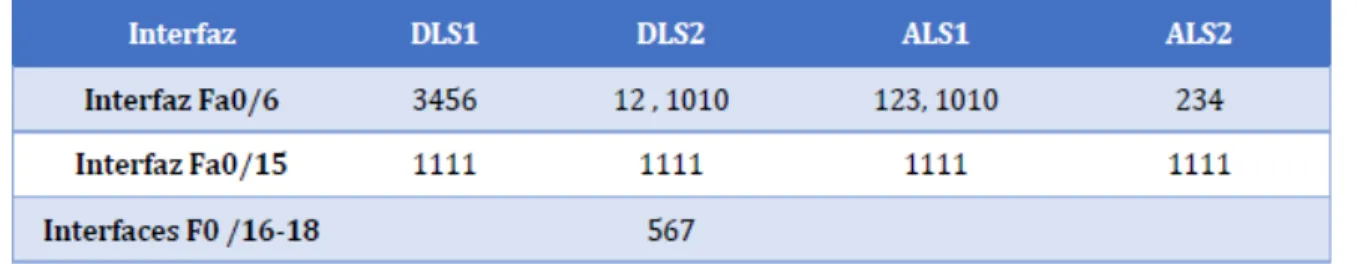
Tabla 2. Asignación de interfaces a Vlans
DLS1:
DLS1(config)#inter fa0/6 Ingresamos interface fa0/6
DLS1(config-if)#sw acc vlan 3456 Configuramos el sw modo access vlan 3456
% Access VLAN does not exist. Creating vlan 3456
DLS1(config-if)#no sh Activamos la interface
DLS1(config-if)#inter fa0/15 Ingresamos interface
fa0/15
DLS1(config-if)#sw acc vlan 1111 Configuramos el sw modo access vlan 1111
% Access VLAN does not exist. Creating vlan 1111
68
%LINK-5-CHANGED: Interface FastEthernet0/15, changed state to down
DLS1(config-if)#
DLS2:
DLS2(config)#inter fa0/6 Ingresamos interface fa0/6
DLS2(config-if)#sw acc vlan 12 Configuramos el sw modo access vlan 12
DLS2(config-if)#sw acc vlan 1010 Configuramos el sw modo access vlan 1010
DLS2(config-if)#no sh Activamos la interface
DLS2(config-if)#inter fa0/15 Ingresamos interface
fa0/15
DLS2(config-if)#sw acc vlan 1111 Configuramos el sw modo access vlan 1111
DLS2(config-if)#no sh Activamos la interface
69
DLS2(config-if)#inter ran fa0/16-18 Ingresamos rango interface fa0/16-18
DLS2(config-if-range)#sw acc vlan 567 Configuramos el sw modo access vlan 567
DLS2(config-if-range)#no sh Activamos la
interface
%LINK-5-CHANGED: Interface FastEthernet0/16, changed state to down
%LINK-5-CHANGED: Interface FastEthernet0/17, changed state to down
%LINK-5-CHANGED: Interface FastEthernet0/18, changed state to down
DLS2(config-if-range)#
ALS1:
ALS1(config)#inter fa0/6 Ingresamos interface fa0/6
ALS1(config-if)#sw acc vlan 123 Configuramos el sw modo access vlan 123
70
ALS1(config-if)#no sh Activamos la interface
ALS1(config-if)#inter fa0/15 Ingresamos interface fa0/15
ALS1(config-if)#sw acc vlan 1111 Configuramos el sw modo access vlan 1111
ALS1(config-if)#no sh Activamos la interface
%LINK-5-CHANGED: Interface FastEthernet0/15, changed state to down
ALS1(config-if)#
ALS2:
ALS2(config)#interfa fa0/6 Ingresamos interface fa0/6
ALS2(config-if)#sw acc vlan 234 Configuramos el sw modo access vlan 234
ALS2(config-if)#no sh Activamos la interface
ALS2(config-if)#interfa fa0/15 Ingresamos interface fa0/15
ALS2(config-if)#sw acc vlan 1111 Configuramos el sw modo access vlan 1111
71
%LINK-5-CHANGED: Interface FastEthernet0/15, changed state to down
ALS2(config-if)#
Part 2: conectividad de red de prueba y las opciones configuradas.
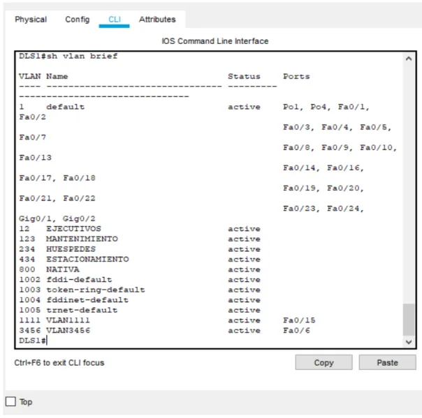
a. Verificar la existencia de las VLAN correctas en todos los switches y la asignación de puertos troncales y de acceso
72
73
74
75
76
77
78
79
b. Verificar que el EtherChannel entre DLS1 y ALS1 está configurado correctamente
DLS1:
Figura 19. Estado de EtherChannel DLS1
80
Figura 20. Estado de EtherChannel DLS2
c. Verificar la configuración de Spanning tree entre DLS1 o DLS2 para cada
VLAN.
81
82
83
84
CONCLUSIONES
Luego del análisis del trabajo podemos entender la gran importancia de la
herramientas Packet Tracer y sus diferentes aplicativos actuales, siendo esta una
herramienta muy precisa para la creación de topologías de redes que permitiendo
la conectividad VLAN, OSPF, EGRIP, NAT, etc; Con esto se pretende que el
estudiante pueda desarrollar mecanismos de protección, conectividad, eficiencia,
comunicación, y demás temas relacionados al montaje de redes LAN/WAN. En los
casos expuestos pudimos analizar mediante evidencias fotográficas el montaje
sencillo de las redes y los comandos usados para ciertas funciones del programa,
lo cual permitió el enrutamiento de los dispositivos y la conectividad de los mismos
85
BIBLIOGRAFÍA
Ø Teare, D., Vachon B., Graziani, R. (2015). CISCO Press (Ed). Basic Network and Routing Concepts. Implementing Cisco IP Routing (ROUTE) Foundation
Learning Guide CCNP ROUTE 300-101. Recuperado de
https://1drv.ms/b/s!AmIJYei-NT1IlnMfy2rhPZHwEoWx
Ø Macfarlane, J. (2014). Network Routing Basics : Understanding IP Routing in
Cisco Systems. Recuperado de
http://bibliotecavirtual.unad.edu.co:2048/login?url=http://search.ebscohost.c
om/login.aspx?direct=true&db=e000xww&AN=158227&lang=es&site=ehost-live
Ø Wallace, K. (2015). CISCO Press (Ed). CCNP Routing and Switching ROUTE
300-101 Official Cert Guide. Recuperado
de https://1drv.ms/b/s!AgIGg5JUgUBthFx8WOxiq6LPJppl
Ø Donohue, D. (2017). CISCO Press (Ed). CCNP Quick Reference. Recuperado de https://1drv.ms/b/s!AgIGg5JUgUBthFt77ehzL5qp0OKD
Ø Hucaby, D. (2015). CISCO Press (Ed). CCNP Routing and Switching
SWITCH 300-115 Official Cert Guide. Recuperado
86
Ø Froom, R., Frahim, E. (2015). CISCO Press (Ed). Network Design Fundamentals. Implementing Cisco IP Switched Networks (SWITCH)
Foundation Learning Guide CCNP SWITCH 300-115. Recuperado de