La version final de este trabajo fue publicadada en la 14th LACCEI International Multi-Conference for Engineering, Education, and Technology: “Engineering Innovations for Global Sustainability”
A Proposed Design for a Smart Shock
Absorber Using an Electro-Rheological Fluid
Ahmed Nooh, Carlos Monroy, Michael Anwr Alphonse Anees and Wafik Girgis
I. INTRODUCTION
A. Why are shock absorbers used in the oil field
Owners of oil and gas wells and drilling operators are mostly concerned about reducing the cost of drilling petroleum wells. One approach to reducing the drilling costs is to develop an optimum drilling programs. A key element of an optimum program involves the use of appropriate drilling tools such as shock absorbers. A shock absorber is a tool which is run in the lower portion of the drill string to reduce shock loading and absorb vibrations produced during the drilling process. It reduces the harmonic frequencies generated in the drill string while drilling. These vibrations, if not minimized by the shock absorber, can result in damage to the drill string, drill bit, and surface drilling equipment. A properly designed shock absorber not only minimizes drill-string vibration, but also helps keep the bit on the bottom of the hole, which increases drilling speed or as referred to in the petroleum engineering discipline, the Rate Of Penetration (ROP).
It is worth mentioning that although the popularity of shock absorbers has grown, a few problems are being reported. The flexibility of the shock absorber (or lack of rigidity), and the high chance of fatigue failure in its components are cited by few in the industry as creating a higher risk of hole-control problems, negating the potential benefits of the tool [1] [2].
B. Drilling vibrations types and problems
Vibrations occur mainly as three main types as shown in figure 1: axial vibration, torsional vibration, and lateral vibration [3].
Figure 1. Vibration Types and effect on the drill-string and drill bit. Source: [3]
1) Axial vibrations: This type of vibrations is the main vibration responsible for the occurrence of Bit Bounce1 while drilling, which by turn causes wear and damage of the drill- string, and the drill bit.
2) Torsional vibration: This type of vibrations is responsible for the irregular downhole rotation that occurs in the drilling operation.
3) Lateral vibration: This type of vibration is responsible for the bending that occurs in the drilling string during the drilling operation.
In this paper, we propose a new design for a smart shock absorber that uses smart fluids to control the axial vibration severity and frequency according to the bit requirements. The goal is not to damp the system too much, which would reduce ROP, or too little, which would cause damage to the equipment as discussed above. This type of smart shock absorbers has been introduced to other industries using smart fluids in hydraulic shock absorbers. Thus, we adapt the concept into the oil and gas industry and propose a design for a shock absorber that can be installed in the drill-string.
II. SMART FLUIDS, THEIR APPLICATIONS IN VIBRATION DAMPING, AND SELECTION OF THE PROPER FLUID FOR THE SMART SHOCK ABSORBER
Over the past few years, smart fluids and particularly the Electro-Rheological Fluid (ERF) and Magneto-Rheological Fluid (MRF), have been used to damp oscillations in systems where critical controllable damping was needed. They have been tested in car dampers, washing machines, robot- arm oscillation damping, computer hard drives…etc [4]. The smart fluids can even exert surplus force, that is- not only damp external forces, but create forces when excited as well. In bioengineering applications, smart fluids are used to move artificial support components such as legs, arms, and even fingers [5].
B. Electro-rheological fluid properties
ERF are composed of a non- conducting liquid with solid particles that are electrically polarizable and dispersed in the liquid [6]. When an ERF is excited by an electrical current, its viscosity changes and accordingly the damping force the ERF can exert on the system changes. Thus, the force is governed by the following equation where dx/dt is the speed at which a vibrating system oscillates and E is the electric field intensity applied to the system:
(1)
There are a few types of ER fluid. We mention two of them in the following section:
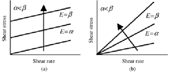
1) Colloidal electro-rheological fluid of the particle dispersion type: The colloidal fluid types possess Bingham fluid characteristics [7]. Hence, it can withstand high shear stress, and act like a solid without straining as shown in fig.2(a) until stress exceeds a certain point in which case, the fluid acts like a viscous liquid and shear rate increases. Of course, the stress force at which strain starts occurring depends on the velocity at which the fluid is moving. (in our case, this would be a function of the vibration frequency occurring downhole).
2) Homogenous electro-rheological fluid
The homogenous ER fluid is composed of low molecular crystals or polymer crystals that has Newtonian characteristics [7]. As soon as shear stress is applied, shear strain occurs, and as soon as shear stress is removed, shear strain disappears. The relationship between shear stress and shear strain is fixed and is linear as seen in fig.2(b).
Figure 2. Characteristics of the two types of ER fluid: (a) particle -type ER fluid, (b) Homogenous ER fluid. Source: [7]
C. Magnetic-rheological fluid properties
Magnetic-Rheological Fluid (MRF) can be excited to produce force rather than produce damping effects only. It is excited by an electromagnetic field of few volts and kilo amperes [8], although newer papers report less power requirement (of few amperes) [9]. It is worth mentioning that MRFs are ferromagnetic in nature, which allows some residual particles to oscillate at energies that are lower than the activation energy of the damping system and consequently bypass the damper into the system, causing loss of the MRF matter [5].
D. Comparing and choosing a smart fluid to be used in the smart shock absorber
1) Power requirement: the power requirements for ERF is in the range of kilovolts and milliamps, while the power requirements to excite an MRF is in the range of kiloamps, and millivolts, thus the power requirements for both is within the same range.
2) sub-fluid particles bypassing the system: as mentioned earlier, the fine particles in the MRF bypass the damper into stagnant positions around the piston or on the walls of the shock absorber. When those fine particles collect on the walls of the container, they exert extra force on the walls, and subsequently affect the wall integrity by time. ERF does not cause such troubles. Thus, according to this criterion, we preferred ERF to be used in the shock absorber.
3) the direction of force created when either of the smart fluid is excited: when the MRF is excited, it creates a force that not only cancels opposite forces (dampening force), but it can further create surplus force within the system. The ERF only creates force when excited to counteract external forces (dampening force) [5]. The difference here may not affect the choosing process much.
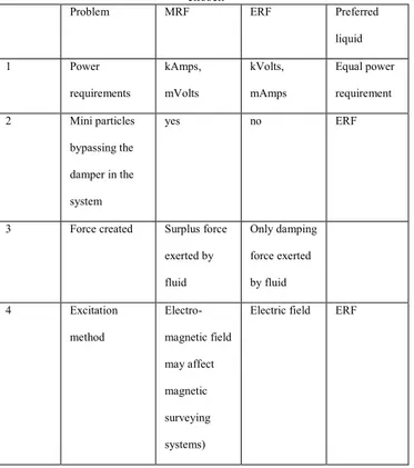
Table 1. Choosing between MRF and ERF- liquid problems and why ERF is chosen
Problem MRF ERF Preferred
liquid
1 Power
requirements kAmps, mVolts kVolts, mAmps Equal power requirement
2 Mini particles
bypassing the
damper in the
system
yes no ERF
3 Force created Surplus force
exerted by
fluid
Only damping
force exerted
by fluid
4 Excitation
method Electro-magnetic field may affect magnetic surveying systems)
Electric field ERF
Table 1 shows a summarized comparison of certain properties of MRF vs. ERF. ERF (whether colloidal or homogenous type) is chosen due to problems 2 and 4 that would occur if an MRF is chosen instead.
III.GOVERNING EQUATIONS OF AXIAL VIBRATION IN A DAMPER
Assume there is a container that contains a viscous fluid and that there is a piston moving against the viscous fluid. In addition, assume that the piston is also moving against a spring and another mechanical damper placed left to the string as shown in figure 3. Next, assume there is a weight, mg attached at the bottom of the containers. Finally, assume that the vibrations are caused at the bottom of the system and they cause the piston to move against the viscous fluid, the spring, and the damper as explained earlier.
The forces exerted on the system are broken down as follows [10]:
1) There is a force generated by the spring and can be quantified as K (spring constant) times the spring elongation. The spring elongation is expressed as ₰st + x, where ₰st is the “equilibrium position” induced by the weight of the shock absorber components, and the
2 POOH: Pull Out Of Hole- a term used in the oil and gas industry to mean pulling the drill-string (composed of many drill pipes and other drilling tools) out of the whole and disassembling it)
additional elongation, x is induced by further external forces on the system, such as axial drilling vibrations, and tensile load due to POOH2 or increasing weight on bit3; we will refer to those external forces as Fe.
2) There is a force generated by the damper element (damper force), 𝑐𝑑𝑟
𝑑𝑡, where 𝑟 = 𝑥 + ₰𝑠𝑡+ land C is the damping
coefficient;
3) The weight of the shock absorber component is mg; 4) Another term that needs to be accounted for is the inertia
force=𝑚𝑑2𝑟
𝑑𝑡2. However, in this case, the inertia force is equal to zero, assuming that there is no rotation in any of the damper components.
Now the forces exerted on the system so far are mentioned as follows:
𝑘(𝑥 + ₰𝑠𝑡) + 𝑐 𝑑𝑟
𝑑𝑡+ 𝑚
𝑑2𝑟
𝑑𝑡2 = 𝑚𝑔 + 𝑓𝑒. (2)
Since inertia force is equal to zero,
𝑘(𝑥 + ₰𝑠𝑡) + 𝑐 𝑑𝑟
𝑑𝑡+ 0 = 𝑚𝑔 + 𝑓𝑒. (3)
Further, to add the effect of the viscous fluid to the governing equation, [10] modelled the damping force, Ff due to a piston pressing against a viscous fluid (the ERF in this case) with the following equation:
𝐹𝐹= −𝑘𝑜𝑚 𝑑2𝑥
𝑑𝑡2− 𝑐𝑓
𝑑𝑥
𝑑𝑡, (4)
where cf is the fluid damping coefficient which depends on the fluid viscosity.
Combining 3 and 4, the final governing equation of the system is as follows:
𝑘(𝑥 + ₰𝑠𝑡) + 𝑐 𝑑𝑟
𝑑𝑡+ 𝑘𝑜𝑚
𝑑2𝑥
𝑑𝑡2+ 𝑐𝑓
𝑑𝑥
𝑑𝑡 = 𝑚𝑔 + 𝑓𝑒. (5)
3 Weight on bit (WOB): a term used in the oil and gas industry to measure the weight exerted by the drill-string on the drill bit. WOB is necessary to achieve high drilling speed or ROP.
V.OPTIMUM PLACEMENT OF A SHOCK ABSORBER IN THE DRILLING STRING
How much we can benefit from a shock absorber during drilling a well depends on the placement of the tool in the drill string. The proper placement of the tool depends upon the type of Bottom Hole Assembly (BHA)8 to be used, the types of formations to be drilled, and their tendency to cause deviation while drilling.
In general, it is recommended that whenever possible the shock absorber be placed directly above the bit. This position in the drill string will provide the maximum benefit from the tool [1]. However, there are cases where certain drilling tools need to be installed above the drill bit. The most important case is building an angle (also called building inclination) in a directional well as in fig 5 below. To build an angle, a stabilizer needs to be installed right above the bit [11, 12] , thus the shock absorber may need to be shifted upwards, sacrificing a little portion of the damping efficiency.
When formations which present minimum deviation tendencies are drilled or when there is no need to drill a directional well - negating the requirement for reamers or stabilizers to be used (slick string) - the shock absorber should be placed directly above the bit.
Also, when the BHA is configured to drop the angle after building enough inclination in a directional well, a BHA assembly that is called a pendulum assembly is used where the stabilizers are only installed distant from the bit [11, 12],
8 BHA or bottom hole assembly is the lowest part of the drill string. It may be composed of several stabilizers, reamers, shock absorbers, and other drilling tools.
allowing for enough space to install the shock absorber as close as possible from the bit.
There are other problems that necessitate using a tool right above the bit instead of using a shock absorber. For instance, a reamer may be required right above the bit to maintain the wellbore diameter constant (maintain gauge). In such case, the drilling engineer will be forced to place the shock absorber(s) above the reamer as in figure 6 below. In general, it is better to place the shock absorber right above the bit unless it is necessary to shift it upwards and use another tool instead. This condition should also apply to using the smart shock absorber.
CONCLUSION
Shock absorbers have been found beneficial for drilling economics. They reduce drilling time by increasing bit-formation contact time and elongating the bit lifetime. Vibrations cause damage to the drill-bit and drill-string. Axial vibration is a type of vibration where the drill string bounces off the formation while drilling. We proposed a smart shock absorber that measures the vibration frequency and intensity, compares it to the recommended range of vibration required to achieve the highest rate of penetration. If the measured vibration parameters are found to be higher than the recommended range, an electronic controller produces an electric field that excites an electrorheological fluid within the shock absorber. Based on the intensity of the electric field and time of exposure, the viscosity of the electrorheological fluid increases. The fluid then acts as a hydraulic damper for the axial
Figure 5. Building, hold and drop assemblies. Source: directionaldrilling.blogspot.fr and [11].
vibrations. This kind of automated control will optimize the well drilling parameters based on the needed degree of vibrations. Finally, we discussed the optimum placement of a shock absorber in the drill-string; and cases where the optimum placement of a shock absorber will be compromised to allow more critical tools to be installed where the shock absorber should be to make the drilling process more effective.
ACKNOWLEDGEMENT
![Figure 1. Vibration Types and effect on the drill-string and drill bit. Source: [3]](https://thumb-us.123doks.com/thumbv2/123dok_es/6829409.835849/1.918.275.645.526.779/figure-vibration-types-effect-drill-string-drill-source.webp)
![Figure 5. Building, hold and drop assemblies. Source: directionaldrilling.blogspot.fr and [11]](https://thumb-us.123doks.com/thumbv2/123dok_es/6829409.835849/5.918.494.855.74.405/figure-building-hold-drop-assemblies-source-directionaldrilling-blogspot.webp)
