Borja Bordel S´anchez1∗, Ram´on Alcarria2, Diego S´anchez-de-Rivera1, and ´Alvaro S´anchez-Picot1 1Department of Telematics Systems Engineering. Universidad Polit´ecnica de Madrid
{bbordel, diegosanchez, asanchez}@dit.upm.es
2Department of Topographic Engineering and Cartography. Universidad Polit´ecnica de Madrid
Abstract
One of the most interesting applications of Industry 4.0 paradigm is enhanced process control. Tradi-tionally, process control solutions based on Cyber-Physical Systems (CPS) consider a top-down view where processes are represented as executable high-level descriptions. However, most times indus-trial processes follow a bottom-up model where processes are executed by low-level devices which are hard-programmed with the process to be executed. Thus, high-level components only may super-vise the process execution as devices cannot modify dynamically their behavior. Therefore, in this paper we propose a vertical CPS-based solution (including a reference and a functional architecture) adequate to perform enhanced process control in Industry 4.0 scenarios with a bottom-up view. The proposed solution employs an event-driven service-based architecture where control is performed by means of finite state machines. Furthermore, an experimental validation is provided proving that in more than 97% of cases the proposed solution allows a stable and effective control.
Keywords: Cyber-Physical Systems, Industry 4.0, Process Control, State Machine, Legacy Systems
1
Introduction
In the last ten years many solutions based on Cyber-Physical Systems (CPS) [1] have been proposed: from Ambient Intelligence (AmI) and healthcare systems [2] to traceability solutions [3]. However, the best opportunity to develop relevant products based on CPS was born in 2014 with the Industry 4.0 paradigm [4]. Industry 4.0 refers to the deep integration of next generation information technologies (such as CPS or AmI) into industrial scenarios, solutions and procedures. In that way, innovations about CPS finally could be applied to a particular application scenario, and specific and tangible contributions would be expectable.
As CPS are usually defined as integrations of computation with physical processes [5], the most direct application of CPS in Industry 4.0 scenarios is enhanced process control. In fact, traditional process control is based on closed feedback loops [6] where (i) data about the process are collected using sensors, (ii) the acquired information is processed and the actions to be taken are calculated and (iii) actuators change their state along the calculated decisions. On the contrary, CPS may enhance traditional process control as they refer a class of devices being able to get synchronized with physical processes [7]. In that way, it is not necessary to define additional feedback loops, as CPS integrates all the mechanisms to reach and maintain a synchronized state.
Depending on the defined architecture, data flow in CPS may be vertical, horizontal or even transver-sal. Any case, most proposals on CPS-based process control describe systems where processes are
Journal of Wireless Mobile Networks, Ubiquitous Computing, and Dependable Applications, 7:4 (December 2016), pp. 41-64
defined by users using high-level languages, which are later translated into executable code [8]. This code is, finally, executed by hardware devices. In general, this approach is known as top-down view [9]. However, in real industrial scenarios, processes used to be hard-programmed into low-level devices, and no interface to modify that programming is publicly offered. Devices only notify important events or changes by activating a flag which may be monitored using technologies such as OPC [10]. This situa-tion is the final cause of the implementasitua-tion of supervisory control systems such as SCADA [11] which may integrate all the flags from devices and translate them into human-readable information. This ap-proach is usually known as bottom-up view. The authors argue that CPS-based process control systems for Industry 4.0 have to be designed to replace the old supervisory control systems, integrating hardware devices into new and enhanced process control solutions. New CPS architectures and solutions following a bottom-up approach are, then, required.
Therefore, in this paper, a new solution for bottom-up process control systems based on CPS is described. The presented solution includes a reference architecture which is defined from the numerous proposals which have been described in the research literature and from the particular requirements of Industry 4.0 scenarios. A detailed functional architecture is also provided, whose behavior is based on the sending of events among the different components which made up the system. The entire solution is based on the concept of service, which is complemented with finite state machine technologies such as Amazon States Language (ASL). Furthermore, in order to guarantee a stable control, the described solution supports executions with a guarantee Quality-of-Service (QoS).
The rest of the paper is organized as follows: Section 2 presents the state of the art in CPS architec-tures and process control systems. Section 3 presents the contributions of the article. Section 4 describes the experimental validation. Finally, Section 5 and 6 explain some results of this experimental validation and the conclusions of our work.
2
State of the art
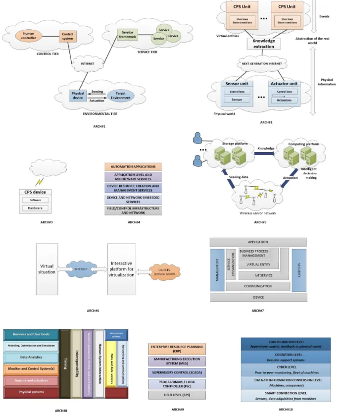
Ten relevant CPS reference architectures have been described in research literature or in different drafts by standardization organizations [12]. Namely (Figure 1 represents all of them):
• ARCH#1. Service-based CPS architecture. Proposed by La et al. [13], it is the architecture most similar to the traditional process control systems. Basically, it consists on a physical platform, a control system and, as a novelty; a service framework which allows performing control tasks by means of Internet services (which provides a higher flexibility). Its main disadvantage is its low integration level, which should be improved in order to advance towards more efficient solutions as required by Industry 4.0. Moreover, deploying advanced functionalities (as Industry 4.0 requires) may be complicated if tiers are not explicitly independent and adapted. Thus, additional modules should be added in order to improve its usability.
Figure 1: Most important proposed architectures on CPS
• ARCH#3. EuroCPS project architecture. This architecture was proposed as a result of the Euro-pean project EuroCPS [15]. Basically it represents CPS as a networked collection of embedded devices. It is a very flexible proposal; as almost any current system may be understand as a col-lection of networked devices. However, it is too much general to meet the specific requirements of Industry 4.0 scenarios (for example, it is not clear how to deploy an enhanced control system).
• ARCH#4. IoT@Work project architecture. Proposed as a result of the IoT@Work project [16], it was not proposed as a CPS architecture (originally was designed to Internet-of-Things systems). However, some authors have employed it in CPS applications, so should be considered in this group. It is a very conceptual architecture made of five different layers. It is a service-based proposal which addresses problems such as the inter-layer operation. However, it was designed with a top-down view which does not fill at all with Industry 4.0 scenarios. Moreover, it is focused on the deployment of automation applications, which is only a particular case in the Industry 4.0 environment. It is a valuable approach, although, in general, it should be more specific (considering some Industry 4.0 problems such as the geographically spared production locations).
• ARCH#5. CPS architecture model. Proposed by Wan et al. [17], this architecture is very focused on hardware components. Three different subsystems are distinguished: wireless sensors net-work, storage and applications platform and a computing system. This structure is very similar to ARCH#1 and to the traditional process control systems. Its integration level should be improved and connections with other technological systems (such as cloud computing infrastructures) are not clearly indicated as required by Industry 4.0 paradigm. As important characteristic, for first time, an intelligent decision making system (as well as humans) is considered in order to obtain the actuator responses.
• ARCH#6. Networked CPS architecture. This architecture was proposed by Lai [18] using very traditional concepts about ordinary distributed systems. It is pretty similar to ARCH#2, and shows the same difficulties to be applied to Industry 4.0 scenarios. As a difference, it explicitly considers an adaptation layer between the virtual entities and the physical world (an important characteristic which should be considered in later proposals).
• ARCH#7. ISO-IEC architecture. Proposed by the ISO organization [19], it was designed as ar-chitecture for the Internet-of-Things and, later, it was applied to CPS. As ARCH#4 it is a very conceptual proposal, although it is much more exhaustive. As a novelty, it mixes both concepts: virtualization and a service-based approach. As a main disadvantage, it does not consider an in-formation extraction module or any similar instrument to become independent the low-level infor-mation from the high-level data. Additionally, this architecture is designed following a top-down view, which does not meet the requirement of Industry 4.0 paradigm. However, it is important to remark the inclusion of a layer dedicated to process management at business level.
• ARCH#9. AIOTI (EC) architecture. The European Alliance for Internet of Things Innovation (AIOTI) has recently proposed an alternative architecture for CPS [21]. This proposal is also focused on industrial solutions, although it is much more conservative that which proposed by NIST. In particular, it maintains the same structure of traditional process control systems (including the SCADA systems), changing the ordinary sensors and actuators for some embedded devices they called Cyber-Physical Systems. It is very complicated to fit Industry 4.0 new designs to AIOTI architecture, so it has not been almost employed in third-party proposals.
• ARCH#10. 5C architecture. Proposed by Lee et al. it is the first architecture proposed for Industry 4.0 systems. It is a very remarkable proposal, although it is complicated to be used as base for real developments. It describes five kinds of functions and/or modules which should be present in every CPS in order to fulfill Industry 4.0 requirements. However, capital issues about information technologies (communications, security, data format, etc.) are not addressed, so this proposal used to be employed to check that a certain system meets the Industry 4.0 requirements instead of as a reference architecture.
Considering all the previous discussions, our proposal will be based on NIST architecture, to which some slightly modifications will be added (see Section 3.1). Moreover, it will be checked considering all the functions and requirements showed by 5C architecture.
Apart from general CPS architectures which could be employed to develop Industry 4.0 systems, some specific works on process control systems based on CPS may be found [22]. These proposals are not very numerous and mostly focused on Smart Grids. These works are usually previous to the CPS definition, but in some occasions the authors employ this paradigm to develop the control subsystem [23] [24]. On the other hand, proposals on pure process control systems based on CPS are rare. In general, they are focused on general aspects about industrial systems [25] or propose process control solutions based on simple networked sensors and actuators (as in ARCH#3) [26].
Our work, then, fulfills a gap in research, proposing a fully functional process control system, con-sidering all the requirements of Industry 4.0 [27]. In order to reach this objective, the previously cited architectures and their main characteristics are taken into account. Thus, an event-driven service-based solution is designed, considering the NIST reference architecture and the concepts of ”state” and ”state transition”.
3
Proposed solution
In this Section the technical solution is described. In the first subsection the reference architecture, as well as a general view of the solution performance, are presented. And, in the second subsection, the technical proposal is presented in detail by means of a specific functional architecture.
3.1 Architectures and overview of the proposal
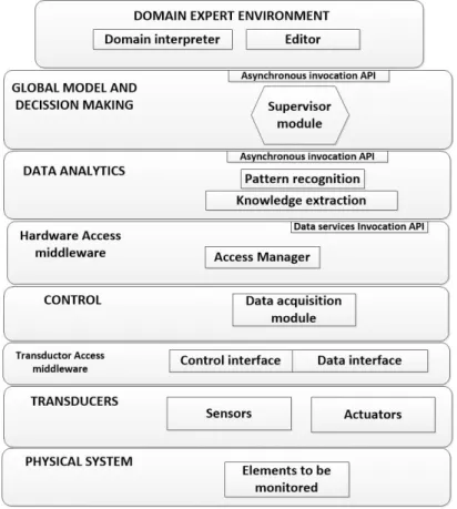
Figure 2 represents the reference architecture considered as base for our proposal. As said before, basi-cally it corresponds with the NIST CPS architecture, where three small modifications have been included. First, two middleware layers have been included in order to show explicitly their existence. Second, the name of the top layer has been modified to clearly show their functions. And, finally, some important components have been remarked inside each layer.
A brief explanation about the proposed architecture (layer by layer) is provided below:
Figure 2: Reference architecture
2. Transducers. It includes both, sensor and actuators. It usually are embedded into the physical system as are included in the same case that the production systems. It refers the modules in charge of monitoring the system activity and activate (or not) a certain flag in the system’s hardware interface. This module also may monitor certain input flags in order to trigger a new function or stop the system operation.
3. Transductor access middleware. It refers the protocol employed to transport the information pro-vided by transducers towards the control layer, where a data message codifying the obtained infor-mation will be constructed. In most industrial scenarios it is based on the OPC protocol. Although previously only a data interface has been described, in some occasions a control interface could be also available. The system behavior would be the same in both cases, so in this work we are only considering a data interface.
4. Control. It manages the data acquisition by means of the transductor access middleware and elab-orates the data format to be transmitted to the higher layers. On the other hand, it interpreters the messages form the high-level components and orders the appropriate changes in the actuators using the cited middleware. In some cases, some of these functionalities are directly embedded in production systems (when next generation infrastructures are considered), so all the previous layers are totally integrated making up a self-managed device.
Thus, in this case we are deploying a publication/subscription (P/S) middleware (particularly a MQTT middleware [26]) through which information (expressed as events) is transmitted to pro-cessing and decision making modules. An access manager acting as MQTT broker is also con-sidered. Finally, this layer includes a Data service Invocation API, employed to subscribe (or unsubscribe) to a certain type of events.
6. Data analytics. This layer receives the events from the control layer, processes them and extracts the important information. Depending on the sequence of received events, it also may detect a known pattern. With this information, this layer transmits a new high-level (business) event to the supervisor module. In this case, as only two elements are related in the event transmission no P/S technology is required (moreover, its application would be highly inefficient). Instead of that, an asynchronous invocation API (based, for example, on REST services) is included.
7. Global model and decision making. This layer finally receives the high-level events previously generated and updates the current state. When a certain state is left an output activity may be trigger and, besides, when a new state is reached an input activity might be also executed. These activities, in fact, will be used to robustly control the underlying process being executed by the monitored production infrastructure. At this stage, additionally, connections with other systems would be available if needed. Finally, a new event at prosumer (human-understandable) level is generated in order to update the interface for managers or controllers.
8. Domain expert environment. Using this environment, controllers and/or managers may model the sequence of states a certain process may follow. It is important to note that, in general, a detailed description of the process may be not provided as the process evolution depends on the production system programming (usually provided with a PLC –Programmable Logic Controller-) which is unknown (it uses to be protected proprietary technology). However, the sequence of states (which might be as detailed as possible) is well-known as usually it is defined by the type of industry or process.
With this structure, as said before, the proposed architecture fulfills the requirements of Industry 4.0 systems [28]. In particular, (1) self-configure for resilience, (2) self-adjust for variation and (3) self-optimize for disturbance is provided by an adequate control using the input and output activities described above. A (4) remote visualization for humans is provided with the domain expert environment and (5) decision making is considered in the data analytics layer. Other secondary requirements are supported by the default by the physical system or transducers (such as plug&play).
Table 1 compares the ten described architectures in Section 2 and the solution proposed above. In particular, several important requirements are evaluated, proving our proposal is the unique solution which meets all the described needs for Industry 4.0 scenarios.
Requirements / Functionalities
Architectures for Industry 4.0
#1 #2 #3 #4 #5 #6 #7 #8 #9 #10 Our proposal
High integration level X X X X X X X X
Independent subsystems X X X X X X X X X
Central control unit X X X X X X
Knowledge extraction
module X X X X X X
Specific problems of
Industry 4.0 considered X X X X X X
Bottom-up approach X X X X X X X X X X
Connection with other
systems (cloud. . . ) X X X X X X X X X
Adaptation layers
are considered X X X X X
Interface for
prosumers included X X X X
New CPS era tools
are considered X X X X X X X X
Easy to design a system
using the architecture X X X X X X
Table 1: Comparison among the mentioned architectures
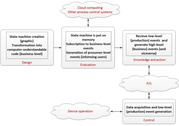
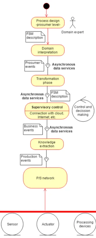
The necessary business-level events to update the state in the supervisor module are provided by the knowledge extraction component, which obtains that information from the processing of the production (low-level) events received from the hardware devices. As many hardware devices could be deployed, a P/S network is the most adequate mechanism to transport the produced events. To this network, control components will be connected in order to generate and receive the production events. Finally, by means of an industrial protocol (such as OPC) and sensors and actuators, control components will obtain and provide the necessary information from/to hardware devices and production systems.
3.2 Detailed explanation
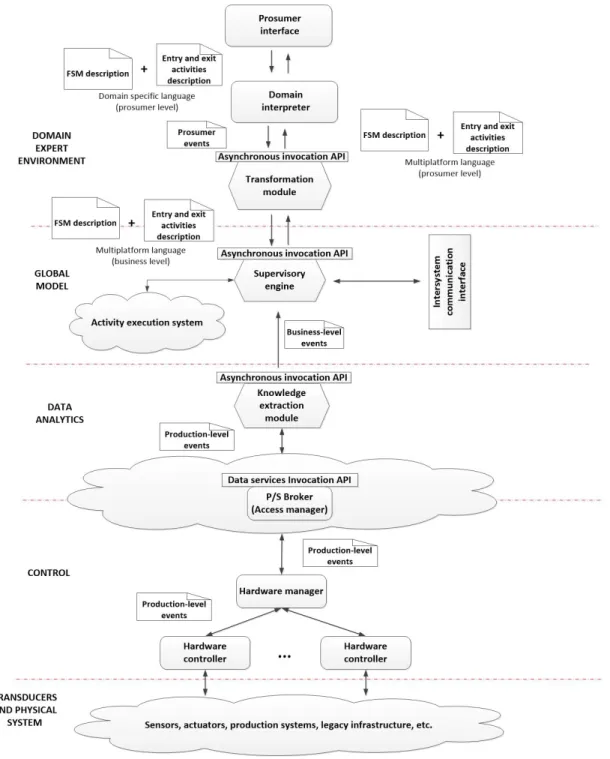
Figure 4 presents the detailed functional architecture of our proposal, and Figure 5 shows a UML diagram describing in a formal way the solution’s behavior.
In order to perform control policies over a certain process, the first step is to design the finite state machine (FSM) which models the process, including the input (or entry) and output (or exit) activities for each state. This first model is constructed using a domain specific language, such as graphic DOT language [29] (employed in many contexts such as manufacturing companies) or the UML state charts [30]. Domain experts, thus, may employ the most adequate language for each scenario and programming skills are not required. Figure 6 represents a generic process modeled as a FSM.
Additionally, the entry and exit activities must be described. As usually said in the literature [3] activities are ordered collections of atomic operations (or service invocations in service-based architec-tures). In the prosumer interface, as it is focused on domain experts, all these elements are described in a high abstraction level which we named as prosumer level. At this level, information is expressed in a human-understandable format which, moreover, is independent from the underlying infrastructure. As in the case of the FSM, in order to describe the entry and exit activities a domain language will be employed. Many languages are available depending on the particular type of industry considered. For example, the Process Specification Language (PSL) [31] may be employed in manufacturing scenarios.
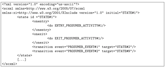
In general, descriptions obtained from prosumer interface will depend on the specific application considered and, furthermore, in some cases various languages could be supported at the same time. Then, in order to homogenize the system operation a domain interpreter is added. This interpreter transforms domain-specific descriptions into generic descriptions, employing common languages such as XML. However, the resulting FSMs and activities are still described at prosumer level. Therefore, it is not required that the obtained code from the interpreter to be executable. Languages such as the XML language for UML state charts [32] or the W3C State Chart XML language [33] could be employed in the FSM descriptions. Finally, activities are modeled using a workflow description XML-based language such as BPMN-XML [34], although is our proposal we are employing YAWL [35]. Figure 7 represents the obtained description from the interpreter using as input the description on Figure 6 and the W3C State Chart XML language.
Figure 4: Detailed functional architecture
Figure 5: UML description of system behavior
process process_example {
STATE#1 [ENTRY="ENTRY_PROSUMER_ACTIVITY#1" EXIT="EXIT_PROSUMER_ACTIVITY#1"]; [...]
FINAL_STATE [ENTRY="ENTRY_PROSUMER_ACTIVITY#F"]; STATE#1 -> STATE#2 [condition=PROSUMER_EVENT#1]; [...]
STATE#N -> FINAL_STATE [condition=PROSUMER_EVENT#F]; STATE#1 -> STATE#N [condition=PROSUMER_EVENT#2]; }
Figure 6: Generic process at prosumer level (prosumer interface). (a) Graphic representation. (b) DOT description
<?xml version="1.0" encoding="us-ascii"?> <scxml xmlns=http://www.w3.org/2005/07/scxml
xmlns:xi=http://www.w3.org/2001/XInclude version="1.0" initial="STATE#1"> <state id ="STATE#1">
<onentry>
<do ENTRY_PROSUMER_ACTIVITY#1/> </onentry>
<onexit>
<do EXIT_PROSUMER_ACTIVITY#1/> </onexit>
<transition event="PROSUMER_EVENT#1" target="STATE#2"/> <transition event="PROSUMER_EVENT#2" target="STATE#N"/> </state>
[...] </scxml>
Figure 7: FSM description generated by the domain interpreter
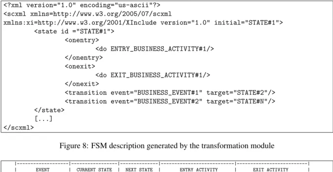
Using the same procedure as described above, this new description is uploaded to a supervisory engine using REST services. In this engine, the adequate execution environment is provided, depending on the language employed in the business-level description. For example, if .NET technologies are employed, a C++ engine is included in this module. If, as in the proposed solution, XML technologies are employed, the uploaded description is transformed into a state transition table (see Figure 9).
<?xml version="1.0" encoding="us-ascii"?> <scxml xmlns=http://www.w3.org/2005/07/scxml
xmlns:xi=http://www.w3.org/2001/XInclude version="1.0" initial="STATE#1"> <state id ="STATE#1">
<onentry> <do ENTRY_BUSINESS_ACTIVITY#1/> </onentry> <onexit> <do EXIT_BUSINESS_ACTIVITY#1/> </onexit>
<transition event="BUSINESS_EVENT#1" target="STATE#2"/> <transition event="BUSINESS_EVENT#2" target="STATE#N"/> </state>
[...] </scxml>
Figure 8: FSM description generated by the transformation module
|---|---|---|---|---| | EVENT | CURRENT STATE | NEXT STATE | ENTRY ACTIVITY | EXIT ACTIVITY | |---|---|---|---|---| | BUSINESS_EVENT#1 | STATE#1 | STATE#2 | ENTRY_BUSINESS_ACTIVITY#1 | EXIT_BUSINESS_ACTIVITY#1 | |---|---|---|---|---| | BUSINESS_EVENT#2 | STATE#1 | STATE#N | ENTRY_BUSINESS_ACTIVITY#N | EXIT_BUSINESS_ACTIVITY#N | |---|---|---|---|---|
| | | | | |
|---|---|---|---|---|
| |
Figure 9: State transition table in the supervisory engine
Finally, the supervisory module may also receive FSM descriptions through the Intersystem com-munication interface. These descriptions are remotely generated, but they must be verified in the local system. Languages employed to describe these remote FSMs may be varied, although JSON-based tech-nologies are the most adequate. In our particular solution, the Amazon States Language is employed [42].
The cited business-level events come from a knowledge extraction module, being able of detecting patterns and other platform-independent information by the analysis of the received production events. This module may implement different technologies [43, 44], depending on the application scenario. This module participates in a P/S network which transports production events from the underlying platform (which executes the process) to the verification system. Production events are expressed in a low ab-straction level and they are platform-dependent (dynamic ranges, error messages, etc. follow a specific format of the installed devices). Almost any P/S technology may be applied, although in this case we have selected MQTT middleware.
MQTT is agnostic in respect to the transmitted messages, so production events may follow the desired format: XML, JSON or a proprietary design [3]. Subscriptions are managed by a broker who acts as
access manager.
Production events are generated and published byhardware controllerswhich are devices in charge of monitoring sensors and changing the state of actuators by means of a standard industrial protocol such as OPC. These sensors and actuators (usually embedded in the production systems and legacy infras-tructures) allow, finally, controlling the process which is being executed by hardware devices. Several
Nevertheless, in our solution, it is only a transparent proxy (usually it analyzes the generated event look-ing for remarkable information, but in this first work we are not considerlook-ing these functionalities).
4
Experimental validation
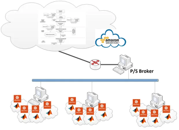
In order to validate the proposed solution as a valid system for process control in Industry 4.0 scenarios, a first real implementation of our proposal was developed. The system was deployed in a laboratory of the Technical University of Madrid, where various emulated production systems were implemented. Three different Linux machines, implementing each one four virtual computers based on Ubuntu 16.04 operating system were started up. Each virtual machine implemented an emulation program representing a different production system provided with an OPC interface. Emulation programs were developed using MATLAB/Simulink tools.
Different electronic device production systems were emulated, in particular three different types were considered: manufacture of diodes, manufacture of capacitors and manufacture of logic gates. Four identical system of each type were implemented. Only one process was programmed in each type of production system. In total, then, three different processes were considered.
The host where each group of four virtual machines was executed acted as hardware controller. A forth computer connected with the other three by means of an Ethernet network acted as hardware manager. In this same fourth computer, the P/S broker was implemented.
The rest of the components in the functional architecture showed in Figure 4 were implemented in the cloud. Specifically, the Amazon Web Services (AWS) were employed (see Figure 10)
Figure 10: Scheme of the deployed infrastructure
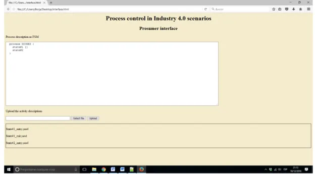
process could be programmed using DOT language. Entry and exit activity description were written using the YAWL designer and were uploaded using the provided form in the same prosumer interface (see Figure 11).
Figure 11: Prosumer interface
Three different experiments were planned in order to validate the proposed solution using the de-scribed implementation.
During the first planned experiment, emulation programs were designed to, randomly, cause mal-functions which the proposed process control solution should address and solve. Malmal-functions presented different levels of severity and requirements in the response time. The experiment was repeated fifteen (15) times. At the end of the experiment, the proposed solution controlled a total of 180 processes. Data about the process evolution were collected for each of the monitored processes. From the analysis of this information we evaluated the performance of the proposed technology.
In order to value and contextualize the obtained results from the first experiment, a second infras-tructure was deployed. It consisted of a traditional supervisory control system. In this new design, the described virtualized production systems were connected to a SCADA system through Programmable Logic Controllers (PLCs). The selected communication protocol was OPC. The SCADA system was developed using the openSCADA [45] project and was hosted in an Amazon Web Services Account (see Figure 12).
The second experiment is focused on the response time of the proposed solution. In fact, in order to provide a stable and robust control the process control system must react before the process state change significantly. This second experiment presents two parts.
In the first part, a fixed number of processes being executed was considered. In this case, ten (10) different processes were included. Then, the number of events per minute generated by the virtual production systems and the virtual sensors was increased. The increasing rate wasr =10eventsmin2 . The
response time was measured in each case. The experiment finished when the response time prevented the system to provide a stable process control.
Figure 12: Traditional supervisory control system
the response time was measured. The experiments finished when the control system could not provide a stable and robust control.
Finally, the third experiment measured the user satisfaction and usability. Some experts on industrial systems (professors and post-graduate students in the Technical University of Madrid) were asked to define some control policies at prosumer level using the interface described in Figure 11. Moreover, they executed the designed control policies using the described infrastructure in the first experiment. Later, they answered a survey in order to evaluate their satisfaction with the system performance and its usability.
5
Results
Figure 13 shows the aggregated results of the experiment described in Section 4. As can be seen in 97.22% of cases, the malfunctions were satisfactory corrected by means of the applied control policies. Only in 2.8% of cases the applied control was unsatisfactory and the process get uncontrolled and, finally, the entire system get blocked. These values are similar, and even slightly better, than showed on other proposals about industrial process control using the CPS paradigm [3].
As said previously, malfunctions in the production systems presented different levels of severity and requirements in the response time, so it is interesting to evaluate the causes of the failures in the proposed process control solution. Figure 14 shows a classification.
Figure 13: Aggregated results
Figure 14: Causes of solution failures
the supervisory engine and, later, to send the taken decision to the emulated systems was too large, so, when applied, control policies were not enough to correct the process evolution. In order to solve this problem, the hardware manager could implement small low-level control rules in order to address in a minimum time critical situations.
Another important case to be taken into account is that, sometimes, malfunctions cannot be resolved. In every industrial scenario there exist some malfunctions that cannot be addressed by means of control policies (mechanical failures, supply failures, etc.), so our proposal should be complemented with other types of systems (such as quality assurance or maintenance chains).
obtained using our technology.
Figure 15: Comparison with traditional systems
This difference, however, is not especially remarkable and may be associated with the years of expe-rience and the hundreds of different and new versions of SCADA published in the last 25 years.
Figure 16 shows the results for the first part of the second experiment, were the response time of the system is evaluated varying the events per minute generated by the virtualized production systems and sensors. As the response time is a stochastic process, the values showed on Figure 16 represent the temporal mean of those processes.
Figure 16: Response time depending on the number of events per minute
The exposed values are much higher than the expected ciphers in a real industrial scenario, so our proposal is perfectly applicable. It must be noted that, if required, the number of hardware managers may be increased in order to create a distributed infrastructure (being able to admit more events per minute).
Figure 17: Percentage of events successfully processed
Results of the second part of the second experiment are showed on Figure 18.
Figure 18: Response time depending on the number of processes being executed
As can be seen, the tendency in the response time depending on the number of processes being executed is very similar to which observed on Figure 16. It presents an exponential evolution where problems appear when more than 50 processes must be controlled at the same time. If the number of processes goes up to 80, the system cannot operate (see Figure 19).
As said previously, the supervisory module may be replicated if more processes should be considered, although, in general, this number is much higher than the medium needs of industry.
Figure 19: Percentage of events successfully processed
Aspects Type of system
Proposed solution Traditional solutions Ease to create
control policies 8.83 6.83
Quality of information in the user interface
4.33 7.13
Flexibility to model
particular processes 8.19 6.59
Correct application
of control policies 9.00 8.91
Detection of
serious errors 7.79 7.65
Table 2: Results of the third experiment
systems. Number 1 implies users found totally inadequate a certain aspect, and number 9 that they found it totally adequate. Number 5 represents indifference. Table 2 shows the medium of all answers.
As can be seen, in general, the proposed solution is better valued by experts than traditional systems. This is especially true when talking about the creation of models and control policies. As the proposed technology allows the definition of policies and models at prosumer level (in a domain expert language), experts feel much more comfortable using the system. However, the proposed interface was only a first prototype, so it was the worst valued aspect in our proposal. Future versions should improve the provided interface, integrating all required tools in a unique window.
6
Conclusions
bottom-up). The proposed technology is based on the NIST reference architecture for CPS, which has been slightly modified. The entire solution is designed to meet the requirements of Industry 4.0 sce-narios. Basically, our proposal consists on an interface where domain experts may model the processes to be controlled as finite state machines. The created model is transformed twice in order to obtain an executable business-level description of the FSM, including two activities per state (the entry and the exit activities) which are employed to apply the control policies. The experimental validation showed that the proposed system presents a performance comparable to the existing control systems, but it also shows all the advantages of the CPS and Industry 4.0 paradigms. Moreover, the described performance may be easily increased if low-level simple control rules are also considered, for which the described solution also contains a module in order to support these functionalities in the future.
Acknowledgments
The research leading to these results has received funding from the Ministry of Economy and Compet-itiveness through SEMOLA project (TEC2015-68284-R) and from the Autonomous Region of Madrid through MOSI-AGIL-CM project (grant P2013/ICE-3019, co-funded by EU Structural Funds FSE and FEDER). Borja Bordel has received funding from the Ministry of Education through the FPU program (grant number FPU15/03977)
References
[1] R. R. Rajkumar, I. Lee, L. Sha, and J. Stankovic, “Cyber-Physical Systems,” in Proc. of the 47th Design Automation Conference (DAC’10), Anaheim, California, USA. ACM, June 2010, pp. 731–736.
[2] S. A. Haque, S. M. Aziz, and M. Rahman, “Review of Cyber-Physical System in Healthcare,”International Journal of Distributed Sensor Networks, vol. 2014, no. 4, pp. 1–20, April 2014.
[3] B. Bordel S´anchez, R. Alcarria, D. Mart´ın, and T. Robles, “TF4SM: A Framework for Developing Traceabil-ity Solutions in Small Manufacturing Companies,”Sensors, vol. 15, no. 11, pp. 29 478–29 510, November 2015.
[4] H. Lasi, P. Fettke, T. Feld, and M. Hoffmann, “Industry 4.0,”Business & Information Systems Engineering, vol. 6, no. 4, October 2014.
[5] Edward A. Lee, “Cyber-Physical Systems - Are Computing Foundations Adequate?” inPosition Paper for NSF Workshop On Cyber-Physical Systems: Research Motivation, Techniques and Roadmap, vol. 2. UC Berkeley, October 2006.
[6] J. C. Doyle, B. A. Francis, and A. R. Tannenbaum,Feedback Control Theory. Dover Publications, 2009. [7] Y. Yalei and Z. Xingshe, “Cyber-Physical Systems Modeling Based on Extended Hybrid Automata,” inProc.
of the 5th International Conference on Computational and Information Sciences (ICCIS’13), Hubai, China. IEEE, June 2013, pp. 1871–1874.
[8] H. Fawzi, P. Tabuada, and S. Diggavi, “Secure Estimation and Control for Cyber-Physical Systems Under Adversarial Attacks,”IEEE Transactions on Automatic Control, vol. 59, no. 6, pp. 1454–1467, Junuary 2014. [9] M. Conti, S. K. Das, C. Bisdikian, M. Kumar, L. M. Ni, A. Passarella, G. Roussos, G. Tr¨oster, G. Tsudik, and F. Zambonelli, “Looking Ahead in Pervasive Computing: Challenges and Opportunities in the Era of Cyber–Physical Convergence,”Pervasive and Mobile Computing, vol. 8, no. 1, pp. 2–21, February 2012. [10] J.-P. Chou, L.-C. Chen, Y. Zhang, and L.-H. Pan, “OPC Unified Architecture for Industrial Demand
Re-sponse,”International Journal of Security and Its Applications, vol. 6, no. 2, pp. 275–280, April 2012. [11] S. A. Boyer,Scada: Supervisory Control And Data Acquisition 4th edition. International Society of
Au-tomation, 2009.
Conference on Ubiquitous Computing and Ambient Intelligence. Sensing, Processing, and Using Environ-mental Information (UCAml’15), Puerto Varas, Chile, ser. Lecture Notes in Computer Science, vol. 9454. Springer International Publishing, December 2015, pp. 144–149.
[13] H. J. La and S. D. Kim, “A Service-Based Approach to Designing Cyber Physical Systems,” inProc. of the 9th International Conference on Computer and Information Science (ICIS’10), Kaminoyama, Japan. IEEE, August 2010, pp. 895–900.
[14] Y. Tan, S. Goddard, and L. C. P´erez, “A Prototype Architecture for Cyber-Physical Systems,”ACM SIGBED Review, vol. 5, no. 1, pp. 1–2, January 2008.
[15] EuroCPS project, https://www.eurocps.org/ [Online; Accessed on December 10, 2016].
[16] A. M. Houyou, “Internet of things at work: Architecture approach to interoperability,” Presentation slide at IoT Interoperability Workshop Paris, March 2012, http://www.probe-it.eu/wp-content/uploads/2012/04/ 11-IoT@Work Interoperability-Architecture.pdf [Online; Accessed on December 10, 2016].
[17] J. Wan, M. Chen, F. Xia, L. Di, and K. Zhou, “From Machine-to-Machine Communications towards Cyber-Physical Systems,”Computer Science and Information Systems, vol. 10, no. 3, pp. 1105–1128, June 2013. [18] C.-F. Lai, Y.-W. Ma, S.-Y. Chang, H.-C. Chao, and Y.-M. Huang, “OSGi-based services architecture for
Cyber-Physical Home Control Systems,”Computer Communications, vol. 34, no. 2, pp. 184–191, February 2011.
[19] “ISO Study Report on IoT Reference Architectures/Frameworks,” August 2014, http://www.sis.se/PageFiles/ 15118/Study%20Report%20on%20IoT%20Reference%20Architectures%20and%20Frameworks.pdf [On-line; Accessed on December 10, 2016].
[20] NIST Cyber-Physical Systems, http://www.nist.gov/cps/ [Online; Accessed on December 10, 2016]. [21] “Alliance for internet of things innovation report,” Report: AIOTI WG11 – Smart manufacturing, http:
//www.aioti.org/wp-content/uploads/2016/10/AIOTIWG11Report2015.pdf [Online; Accessed on December 10, 2016].
[22] S. Wang, J. Wan, D. Li, and C. Zhang, “Implementing Smart Factory of Industrie 4.0: An Outlook,” Interna-tional Journal of Distributed Sensor Networks, vol. 12, pp. 1–10, January 2016.
[23] S. Sridhar, A. Hahn, and M. Govindarasu, “Cyber–Physical System Security for the Electric Power Grid,”
Proc. of the IEEE, vol. 100, no. 1, pp. 210–224, January 2012.
[24] A. W. Colombo,Industrial Cloud-Based Cyber-Physical Systems. Springer International Publishing, 2014. [25] Y. Wang, M. C. Vuran, and S. Goddard, “Cyber-Physical Systems in Industrial Process Control,” ACM
SIGBED Review, vol. 5, no. 1, pp. 1–2, January 2008.
[26] R. Alcarria, T. Robles, A. Morales, and E. Cede˜no, “Resolving Coordination Challenges in Distributed Mo-bile Service Executions,” International Journal of Web and Grid Services, vol. 10, no. 2/3, pp. 168–191, April 2014.
[27] B. Bordel, D. S´anchez-de Rivera, A. S´anchez-Picot, and T. Robles, “Physical Processes Control in Industry 4.0-Based Systems: A Focus on Cyber-Physical Systems,” inProc. of the 10th International Conference on Ubiquitous Computing and Ambient Intelligence (UCAml’16), San Bartolom´e de Tirajana, Gran Canaria, Spain. Springer International Publishing, November 2016, pp. 257–262.
[28] J. Lee, B. Bagheri, and H.-A. Kao, “A Cyber-Physical Systems architecture for Industry 4.0-based manufac-turing systems,”Manufacturing Letters, vol. 3, pp. 18–23, January 2015.
[29] E. Gansner, E. Koutsofios, and S. North, “Drawing graphs with dot,” AT&T Bell Laboratories, Tech. Rep. 910904-59113-08TM, 2006.
[30] J. Lilius and I. P. Paltor, “Formalising UML State Machines for Model Checking,” inProc. of the Unified Modeling Language: Beyond the Standard Second International Conference Fort Collins (UML99’), Col-orado, USA, ser. Lecture Notes in Computer Science, vol. 1723. Springer Berlin Heidelberg, October 1999, pp. 430–444.
[31] L. Qiao, S. Kao, and Y. Zhang, “Manufacturing Process Modelling using Process Specification Language,”
The International Journal of Advanced Manufacturing Technology, vol. 55, no. 5, pp. 549–563, July 2011. [32] J. L. Risco-Mart´ın, S. Mittal, B. P. Zeigler, and J. M. De La Cruz, “From UML State Charts to DEVS
Engineering Lanuages and Systems (MODELS’07), Nashville, Tennessee, USA, January 2007, pp. 35–48. [33] “State Chart XML (SCXML): State Machine Notation for Control Abstraction,” W3C Recommendation,
September 2015, https://www.w3.org/TR/scxml/ [Online; Accessed on December 10, 2016].
[34] B. Silver,Bpmn Method and Style, 2nd Edition, with Bpmn Implementer’s Guide. Cody-Cassidy Press, 2011.
[35] W. van der Aalst and A. ter Hofstede, “YAWL: Yet Another Workflow Language,” Information Systems, vol. 30, no. 4, pp. 245–275, June 2005.
[36] M. zur Muehlen, J. V. Nickerson, and K. D. Swenson, “Developing Web Services Choreography Stan-dards—the Case of REST vs. SOAP,”Decision Support Systems, vol. 40, no. 1, pp. 9–29, July 2005. [37] M. C. Browne and E. M. Clarke, “SML-a high level language for the design and verification of finite state
machines,” Technical Report. Carnegie Mellon University, Tech. Rep. 1565, 1985.
[38] M. Anlauff and M. Anlauff, “Xasm - An Extensible, Component-Based Abstract State Machines Language,” inProc. of the International Workshop on Abstract State Machines - Theory and Applications (ASM’00), Monte Verit`a, Switzerland, ser. Lecture Notes in Computer Science, vol. 1912. Springer Berlin Heidelberg, March 2000, pp. 69–90.
[39] “.NET framework for State Machine Workflows,” https://msdn.microsoft.com/en-us/library/ee264171(v=vs. 110).aspx [Online; Accessed on December 10, 2016].
[40] W. Du, M.-C. Shan, and A. Elmagarmid, “Pre-locking scheme for allowing consistent and concurrent workflow process execution in a workflow management system,” US Patent: US6078982 A, June 1998, http://www.google.tl/patents/US6078982.
[41] I. Altintas, C. Berkley, E. Jaeger, M. Jones, B. Ludascher, and S. Mock, “Kepler: An Extensible System for Design and Execution of Scientific Workflows,” inProc. of the 16th International Conference on Scientific and Statistical Database Management (SSDBM’04), Santorini Island, Greece. IEEE, June 2004, pp. 423– 424.
[42] “Amazon States Language specification,” https://states-language.net/spec.html [Online; Accessed on Decem-ber 10, 2016].
[43] C. H. Chen, L. F. Pau, and P. S. P. Wang,Handbook of Pattern Recognition and Computer Vision. World Scientific, 1993.
[44] O. Maimon and L. Rokach,Data Mining and Knowledge Discovery Handbook. Springer US, 2010. [45] OpenSCADA, http://openscada.org [Online; Accessed on December 10, 2016].
Author Biography
Borja Bordel received the B.S. degree in telecommunication engineering in 2012 and the M.S. telecommunication engineering in 2014, both from Technical University of Madrid. He is currently pursuing the Ph.D. degree in telematics engineering at Telecommunication Engineering School, UPM. His research interests include Cyber-Physical Systems, Wireless Sensor Networks, Radio Access Technologies, Commu-nication Protocols and Complex Systems.
Ram´on Alcarriareceived his M.S. and Ph.D. degrees in Telecommunication Engi-neering from the Technical University of Madrid in 2008 and 2013 respectively. Cur-rently, he is an assistant professor at the E.T.S.I Topography of the Technical Univer-sity of Madrid. He has been involved in several R&D European and National projects related to Future Internet, Internet of Things and Service Composition. His research interests are Service Architectures, Sensor Networks, Human-computer interaction and Prosumer Environments.
Diego S´anchez de Riveraholds a B.S. and a M.S. degree in Telecommunication En-gineering from Technical University of Madrid. Currently he is a Ph.D. student and works as a research engineer in the Department of Telematics Systems at the E.T.S.I. Telecommunications of the Technical University of Madrid. His research interests are Internet of Things, Sensor Networks, Cyber-physical systems, Electronic displays and Web Development.
´