Abstract— A brief overview of reflectarray antennas mainly
focused on some efficient analysis and design techniques and on recent developments has been presented. A technique based on the local periodicity and Method of Moments in Spectral Domain has been presented as very efficient for the analysis of reflectarray antennas. The technique has been validated by comparing simulations and measurements in several breadboards. Based on the previous analysis technique, several design procedures have been implemented for different antenna performances, including requirements of broad-band, dual-frequency and stringent contoured beams. Finally some recent developments for applications in space and LMDS antennas are presented.
Index Terms—Reflectarray, printed antennas, contoured
beam, multi-beam.
I. INTRODUCTION
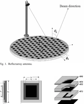
reflectarray is made up of an array of radiating elements which provide a pre-adjusted phasing to form a focused or shaped beam when it is illuminated by a feed, see Fig. 1. The necessary phase shift at each element is obtained by varying one of the geometrical parameters in the reflectarray element. Different implementations of phase-shifters have been demonstrated, as printed patches with attached or aperture-coupled delay lines [1, 2], varying-sized patches in single and stacked configurations [3-6], apertures of different length on the ground plane [7], and others [8-9]. In this paper we consider the reflectarray elements shown in Fig.2, namely stacked patches of varying size and patches aperture-coupled to delay lines, because they provide very good bandwidth performances.
Printed reflectarrays combine certain advantages of reflector antennas and phased arrays. They are manufactured on a planar substrate using printed circuit technology and offer the possibility of beam steering as phased arrays. The feeding method (as in a reflector antenna) eliminates the complexity and losses of the feeding network used in planar arrays, thus providing a higher efficiency. The major limitation of reflectarrays is the narrow-band behavior, but recent
This work was supported in part by the Spanish Commission for Science and Technology from the Ministry of Education and Science under project CICYT TEC 2007- 63650
Jose A Encinar is with the Electromagnetism and Circuit Theory Department, Universidad Politecnica de Madrid, 28040 Madrid, Spain.
developments based on the elements shown in Fig. 2 have significantly overcome this limitation.
Reflectarrays have demonstrated their capability to produce fixed focused and contoured beams, using simple photo-etching techniques. Recently, a lot of work has been done to develop reconfigurable-beam reflectarrays by introducing control devices on the reflecting elements, also some potential applications of reflectarrays in space have been researched such as, contoured beam antennas for Direct Broadcast Satellites (DBS) and very large inflatable antennas.
The purpose of this paper is to present a brief overview of reflectarray antennas, including the analysis and design techniques, bandwidth issues and wideband techniques, as well as recent developments for space and Local Multipoint Distribution System (LMDS) applications.
Analysis, Design and Applications of
Reflectarrays
Jose A. Encinar, Senior Member, IEEE
A
(a) (b)
Fig. 2. Reflectarray element. (a) Stacked patches of varying size, (b) patch aperture-coupled to delay line.
II. ANTENNA ANALYSIS TECHNIQUES
The reflectarray is a relatively complex antenna, and an accurate analysis technique is essential for precise predictions of the radiation features, such as efficiency, gain, co- and cross-polar radiation patterns and bandwidth.
The first step in the analysis of the reflectarray antenna is the characterization of the phasing elements. A full-wave analysis technique must be used to compute the ohmic losses and phase-shift produced on the reflected field on each element. Usually in reflectarrays, mutual coupling cannot be neglected, particularly in the case of varying-sized patches, because the dimensions of some patches are larger than half-wavelength in the dielectric, and the separation between patches is small.
In the case of reflectarrays, which have a large number of elements, the infinite array model can be used and, applying the Floquet’s theorem, the analysis is reduced to only one periodic cell [10-11]. This technique takes automatically into account the mutual coupling among elements and gives good predictions of each element in the array environment.
For multi-layer reflectarray elements, as stacked patches of varying size or aperture-coupled patches, a modular approach based on Spectral-Domain MoM in a periodical environment, described in [12-13], has been used. Spectral Domain Method of Moments is very appropriate and numerically efficient for a full wave analysis of periodical structures, assuming planar arrays of patches or apertures in a single or multi-layer configuration. In this case, the CPU time for the analysis is very low (in the order of 1 second), and the analysis routine can be integrated into an optimization loop for a more accurate design of reflectarray antennas.
The infinite array approach can be used, in principle for any type of phase-shifter element. For elements with stubs of different length (attached or aperture-coupled), all the radiating patches are exactly the same and only the stub length varies from one element to the next. In this case, the infinite array approach will be very accurate, because the coupling produced by the stubs is less significant, assuming a minimum of separation between stubs and other metallic lines or patches.
The complete reflectarray is analyzed by assuming local periodicity, i.e. each element is considered in an array environment with all the elements identical. This approach is accurate when the variation in patch dimensions is smooth from one cell to the next, because it takes into account all mutual coupling between patches. Only in the small number of patches where the surrounding patches are of very different dimensions, the local periodicity approach is not accurate. Normally these elements are a small percentage of the total number of elements and the overall radiation pattern of the reflectarray is slightly affected, as shown in [14].
As an alternative to the local periodicity approach, several full-wave techniques have been applied recently to analyze the reflectarray as a whole [15-17]. These methods take into account all the individual couplings between elements, and them the CPU time is drastically increased. The full wave
techniques are appropriate for an accurate analysis of the reflectarray, but the large CPU times make unaffordable their use in optimization processes.
III. REFLECTARRAY DESIGN
Once the reflectarray element has been defined and characterized, the reflectarray antenna must be designed to produce a given focussed or shaped beam. Once the antenna geometry is defined, the phase- shift distribution to be implemented on the reflectarray is obtained at a given working frequency. Then, the dimensions of the reflectarray elements are adjusted to achieve the required phase-shift. For the case of a reflectarrays based on stacked patches, the dimensions of each patch are determined using an iterative routine for zero finding. This routine calls the analysis program and adjusts the dimensions of each element until the required phase-shift is achieved for each polarisation. After this process, the reflectarray has been design for a given frequency and the radiation patterns fulfil the initial requirements at this frequency, but they suffer some distortion at other frequencies.
The most severe drawback in reflectarray operation is its narrow frequency band, and much effort has been made in recent years to overcome this limitation. First of all, different broad-band elements have been proposed for reflectarray antennas. The two types of reflectarray elements shown in Fig. 2, can provide a broad-band behavior. Using these elements, the design at a single frequency gives enough bandwidth for moderate size reflectarrays [18].
To overcome the frequency band limitation in large reflectarrays, a method has been proposed in [19] for stacked patches of varying size, in which the phase delay is compensated locally at different frequencies with the phase of the reflection coefficient. This means that the patch dimensions are adjusted to match not only the required phase-shift distribution, but also its variation with frequency. The design of a reflectarray in a frequency band is described in [19] and it is summarized as follows: First, using the patch dimension obtained for the design at the central frequency, an optimization routine based on the Fletcher-Powell algorithm is applied to adjust all the dimensions of the stacked patches to match the required phase-shift at central and extreme frequencies. It has been demonstrated that using three stacked patches, a 1-m reflectarray in Ku-band can be designed for a 10% bandwidth [14], [19], for a 15% bandwidth [20], or even for two frequency bands (transmit and receive frequencies) [21].
IV. RECENT DEVELOPMENTS
Several recent developments of reflectarrays for applications in space and base station antennas, which include contour-beam and multi-beam reflectarrays, folded low-profile configurations, Cassegrain offset configurations and beam scanning reflectarrays, are presented in this section.
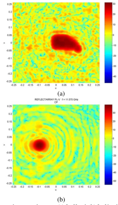
A. Contoured beam reflectarrays for space applications Several contoured beam reflectarrays have been designed for DBS antennas. The design of a contoured-beam reflectarray is divided in two steps. First, a phase-only synthesis technique is applied to obtain the appropriated phase distribution on the reflectarray that generates a predetermined shaped beam with reduced side lobe levels [23]. Then, the dimensions of the patches are adjusted to match the required phase distribution, by using the technique described in previous section. The required bandwidth for communications and broadcasting applications (10%) can be achieved by optimizing the patch dimensions. An “elegant breadboard” (using Space-proven technologies) of a DBS transmit antenna, with a different coverage in each polarisation has been designed, manufactured and tested [14]. This reflectarray antenna, shown in Fig. 3, guarantees a 10% bandwidth and can replace a very expensive spaceborne dual-gridded reflector. The measured radiation patterns in dBi are shown in Fig. 4 for both linear polarizations. The gain contours for 28, 25 and 20 dBi obtained using the analysis technique described in previous section are superimposed to the measurements, showing a good agreement, see Fig. 5. The complete breadboard has also been analysed as a whole by several full-wave and multi-level techniques [15]-[17] and the results are very similar as those shown in Fig. 5.
B. Folded compact reflectarray
Passive reflectarrays with contoured beams have been successfully demonstrated for LMDS Central Station sectored antennas at 26 GHz by UPM in collaboration with University of Ulm (Germany) [24], see Fig. 7. A folded multi-layer printed reflectarray with shaped pattern has been designed, manufactured and tested. The configuration consists of a multi-layer twister reflectarray, a centered feed embedded in its structure and a polarizing grid, which acts as reflector and radome for each polarization, respectively. In order to achieve the pattern specifications along a frequency band (24.5-26.5 GHz), initially a multi-frequency pattern synthesis method,
Z
Y
X FH
FV
E
E
Europe USA
θΗ
θV
(a)
(b)
Fig. 3. Dual-coverage contoured beam reflectarray. (a) Antenna geometry, (b) breadboard.
-0.38 -0.36 -0.34 -0.32 -0.3 -0.28 -0.26 -0.24 -0.22 -0.2 -0.18 -0.05
0 0.05
u
v
Co-polar H-pol, 12.1 GHz
20 20
25 25
28 28
20 20
20 25
25
28
28
theory m eas urements
Fig. 5. Measured and simulated gain contours using local periodicity software from UPM.
(a)
(b)
which relies on a phase-only synthesis, is applied to obtain the required phase-shift on the reflectarray surface for the sectorial cosecant squared beam. Afterwards, the dimensions of the stacked patches, in a three-layer configuration, are optimized to generate the required phase-shift previously synthesized. The measured three-dimensional co-polar patterns are shown in Fig. 6(b). Measurements show a good concordance with theoretical patterns.
C. Multi-beam reflectarrays
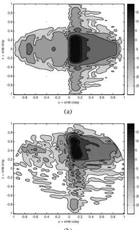
A multi-fed and multi-beam reflectarray has been designed for a central station antenna for LMDS in the 24.5-26.5 GHz band [25]. The antenna produces three independent beams in an alternate linear polarization that are shaped both in azimuth (sectored) and in elevation (squared cosecant). The design process is divided into several stages. First, the positions of the three feeds are established as well as the antenna geometry to produce the three beams in the required directions. Second, the phase distribution on the reflectarray surface, which produces the required beam shaping, is synthesized. Third, the sizes of the printed stacked patches are adjusted so that the phase-shift introduced by them matches the synthesized phase distribution. A breadboard has been manufactured and measured in an anechoic chamber to validate the design process. The drawing and the breadboard with the feed positioned for one lateral beam are shown in Fig. 7. The 3-D radiation patterns for the central and one lateral beam obtained by the analysis technique described in section II are shown in Fig. 8 for the central and
(a)
(b)
Fig. 6. Breadboard (a) and measured pattern at 25 GHz (b) of a folded reflectarray for LMDS base station antenna
(a)
(b)
Fig. 7. Multi-fed reflectarray for LMDS base station antenna. (a) Antenna geometry, (b) breadboard with the feed positioned for one lateral beam.
u = sinθ cosφ
v
=
s
inθ
s
inφ
-1 -0.8 -0.6 -0.4 -0.2 0 0.2 0.4 0.6 0.8 1 -1
-0.8 -0.6 -0.4 -0.2 0 0.2 0.4 0.6 0.8 1
-25 -20 -15 -10 -5 0 5 10 15
(a)
u = sinθ cosφ
v
=
s
inθ
s
inφ
-1 -0.8 -0.6 -0.4 -0.2 0 0.2 0.4 0.6 0.8 1 -1
-0.8 -0.6 -0.4 -0.2 0 0.2 0.4 0.6 0.8 1
-25 -20 -15 -10 -5 0 5 10 15
(b)
one lateral beam. The dimensions of the patches on the reflectarray are symmetrical with respect the XZ plane and so the two lateral beams are symmetrical with respect to the same plane. The measured patterns are in close agreement with the simulations. These results show that several shaped beams can be generated with reflectarray technology in a one feed per beam basis.
D. Dual-offset antenna configurations
The reflectarray antenna can be designed in a dual-reflector configuration using either a Cassegrain or a Gregorian approach. There are several advantages associated with the dual-reflector configuration, such as increase the focal length without increasing the antenna size, to shape or to scan the beam by adjusting only the phase distribution on a small reflectarray used as subreflector.
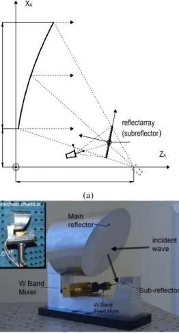
A modular technique has been implemented for the analysis of dual-reflector antennas using a reflectarray as a subreflector [26], see Fig. 9. The analysis technique combines different methods for the analysis of each part of the antenna. First, the real field generated by the horn is considered as the incident field on each reflectarray element [27]. Second, the reflectarray is analyzed with the same technique as for a single offset reflectarray, i.e. considering local periodicity and the real angle of incidence of the wave coming from the feed for
each periodic cell. Third, the main reflector is analyzed using physical optics (PO) technique, where the current on the reflector surface is calculated by summing the radiation from all the reflectarray elements. Finally, the radiation patterns are computed by using the electric field calculated on a projected aperture. This analysis technique has been validated by the design, manufacture and test of a breadboard to focus a beam at an scan angle of 5 degrees with respect the z-axis [28], see Fig. 9(b). The measured patters are in close agreement with the simulations.
E. Beam scanning reflectarrays
The previous dual-offset configuration can be used to scan the beam by adjusting the phase distribution on the sub-reflectarray, which can be implemented by electronic control, and consequently the beam performances can be changed without mechanic devices. The Scanning capabilities of a dual offset antenna of 1.5-m main parabolic reflector with a focal distance equal to 1.5m, and an 50-cm reflectarray have been investigated considering ideal reflectarray elements [26]. The patterns in the YAZA are shown in Fig. 10 for the polarization corresponding to the electric field on the XA direction. The
plots show good performances for a ±2º scanning angles.
V. CONCLUSION
Some efficient analysis and design tools for reflectarray antennas and some recent developments carried out by UPM have been briefly summarized in this paper. The proposed analysis technique based on the local periodicity and Method of Moments in Spectral Domain has demonstrated to be very efficient and accurate for reflectarray antennas. The analysis technique takes into account the angle of incidence and the polarization of the field on each reflectarray element, and considers an accurate model for the feed-horn. The high efficiency of the analysis technique allows its integration in optimization processes, in order to optimize the reflectarray antenna to fulfill the requirements of beam shaping and bandwidth. The analysis and design techniques have been validated by the design manufacture and test of different
-6 -4 -2 0 2 4 6
-10 0 10 20 30 40
Scanning plane: φ=90º | Azimuth cut
θ [deg.]
G
a
in
[
d
B
]
Fig. 10. Radiation patterns on the YAZA plane for electrical beam scanning produced by a progressive phase on the reflectarray.
reflectarray (subreflector)
ZA
XA
(a)
(b)
breadboards, including contoured-beam and multi-beam antennas. The results presented here show the potential capabilities of reflectarrays for DBS antennas, for LMDS central station antennas, and for reconfigurable and beam scanning antennas.
REFERENCES
[1] J. Huang, “Microstrip reflectarray,” IEEE Intl. Symp. Antennas Propagat., Ontario, Canada, pp. 612-615, June 1991.
[2] A.W. Robinson, M.E. Bialkowski, and H.J. Song, “An x-band passive reflect-array using dual-feed aperture-coupled patch antennas”, Asia Pacific Microwave Conference, pp. 906-909, December 1999. [3] D.G. Gonzalez, G.E. Pollon, J.F. Walker, “Microwave phasing
structures for electromagnetically emulating reflective surfaces and focusing elements of selected geometry”, Patent US 4905014, Feb. 1990.
[4] D. M. Pozar and T. A. Metzler, “Analysis of a reflectarray antenna using microstrip patches of variable size,” Electr. Lett. Vol. 29, No. 8, pp.657-658, April 1993.
[5] J. A. Encinar, “Printed circuit technology multi-layer planar reflector and method for the design thereof”, European Patent EP 1 120 856 A1, June 1999.
[6] J.A. Encinar, “Design of Two-Layer Printed Reflectarrays Using Patches of Variable Size”, IEEE Trans. Antennas Propagat., Vol. 49, No. 10, pp.1403-14010, October 2001.
[7] M.R. Chaharmir, J. Shaker, M. Cuhaci, A. Sebak, “Reflectarray with variable slots on ground plane”, IEE Proc.-Microw. Antennas Propag., Vol. 150, No. 6, pp. 436-439. December 2003.
[8] J. Huang, “A Ka-Band Microstrip Reflectarray with Elements Having Variable Rotation Angles”, IEEE Trans. Antennas Propagat., Vol. 46, No. 5, pp. 650-656, May 1998.
[9] M. Bozzi, S. Germani and L. Perregrini, “Performance Comparison of Different Element Shapes Used in Printed Reflectarrays”, IEEE Antennas and Wireless Propagation Letters, vol. 2, pp. 219-222, 2003. [10] D. M. Pozar, and D. H. Schaubert “Analysis of an infinite array of
rectangular microstrip patches with idealized probe feeds”, IEEE Trans. on Antennas Propagat., Vol. 32, pp. 1101-1107, 1984.
[11] D. M. Pozar, “Analysis of an infinite phased array of aperture coupled microstrip patches,” IEEE Trans. on Antennas Propagat., Vol. 37, pp.418-425, April 1989.
[12] Ch. Wan, J.A. Encinar, “Efficient Computation of Generalized Scattering Matrix for Analyzing Multilayered Periodic Structures”, IEEE Trans. Antennas Propagat., Vol. 43, No. 11, pp. 1233-1242, November 1995.
[13] P. Gay-Balmaz, J.A. Encinar, and J.R. Mosig, “Analysis of a Multilayer Printed Arrays by a Modular Approach Based on the Generalized Scattering Matrix”, IEEE Trans. Antennas Propagat., Vol.48, No.1, pp. 26-34, January 2000.
[14] Jose A. Encinar, Leri Datashvili, J. Agustín Zornoza, Manuel Arrebola, Manuel Sierra-Castañer, Jose L. Besada, Horst Baier, Herve Legay, “Dual-Polarization Dual-Coverage Reflectarray for Space Applications”, IEEE Trans. on Antennas and Propag., Vol. 54, No. 10, Pp. 2828-2837, Oct. 2006.
[15] M. Rius, J. Parrón, A. Heldring, J.M. Tamayo, E. Ubeda, “Fast iterative solution of integral equations with Method of Moments and Matrix Decompositions Algorithm- Singular Value Decomposition”, IEEE Trans. on Antennas and Propag., Vol. 56, No. 8, Pp. 2314-2324, August 2008.
[16] M Bercigli, M Bandinelli, P de Vita, A. Freni, “Acceleration Methods for Full-Wave Modelling of Reflectarrays”, The Second European Conference on Antennas and Propagation (EuCAP 2007), 11 - 16 November 2007, EICC, Edinburgh, UK.
[17] F. Cátedra, I. González , A. Tayebi, J. Gómez, “Full wave analysis of reflectarrays antennas”, 30th ESA Antenna Workshop on Antennas for Earth Observation, Science, Telecommunication and Navigation Space Missions, Noordwijk (The Netherlands), 27-30 May, 2008.
[18] D. M. Pozar, “Bandwidth of reflectarrays”, Electronics Letters, Vol. 39, Issue 21, 16 Oct. 2003 Page(s):1490 – 1491.
[19] J. A. Encinar, J. A. Zornoza, “Broadband design of three-layer printed reflectarrays”, IEEE Transactions on Antennas and Propagation. Vol. 51, July 2003.
[20] J. A. Encinar, M. Arrebola, M. Dejus and C. Jouve, “Design of a 1-metre reflectarray for DBS application with 15% bandwidth”, European Conference on Antennas and Propagation (EuCAP 2006), 6 - 10 November 2006, Nice, France
[21] J. A. Encinar, M. Arrebola, “Design of a TX/RX Reflectarray Antenna for Space Applications “, The Second European Conference on Antennas and Propagation (EuCAP 2007), 11 - 16 November 2007, EICC, Edinburgh, UK.
[22] E. Carrasco, J. A. Encinar, M. Barba, “Bandwidth Improvement in Large Reflectarrays by Using True-Time Delay”, IEEE Trans. on Antennas and Propagat., Vol. 56, Issue 8, Part 2, Aug. 2008 Page(s):2496 – 2503.
[23] J. A. Zornoza, Jose A. Encinar, “Efficient Phase-Only Synthesis of Contoured Beam Patterns for Very Large Reflectarrays”, International Journal of RF and Microwave Computer-Aided Engineering. Pp.415-423, Sept. 2004.
[24] J. A. Zornoza, R. Lebber, J. A. Encinar, W. Menzel, “Folded multi-layer microstrip reflectarray with shaped pattern” , IEEE Trans. on Antennas and Propag. Vol. 54, No. 2, Pp. 510-518, Feb. 2006.
[25] M. Arrebola, J. A. Encinar, M. Barba, “Multifed Printed Reflectarray With Three Simultaneous Shaped Beams for LMDS Central Station Antenna”, IEEE Trans. Antennas Propag., vol. 56, No. 6, June 2008, pp. 1518-1527.
[26] M. Arrebola, L. de Haro and J. A. Encinar, “Analysis of dual-reflector antennas with a reflectarray as subreflector”, accepted for publication in the IEEE Antennas Propag. Magazine, 2008.
[27] M. Arrebola, Y. Álvarez, J. A. Encinar and F. Las-Heras, “Accurate analysis of printed reflectarrays considering the near field of the primary feed”, accepted for publication in the IET Microwave, Antennas and Propagation, 2008.
[28] M. Arrebola, W. Hu, J.A. Encinar, R. Cahill, V. Fusco, H.S. Gamble and N. Grant “94 GHz Beam Scanning Dual-Reflector Antenna With a Sub-Reflectarray”, 30th ESA Antenna Workshop on Antennas for Earth Observation, Science, Telecommunication and Navigation Space Missions, Noordwijk (The Netherlands), 27-30 May, 2008
José A. Encinar (S’81-M’86) was born in Madrid, Spain. He received the Electrical Engineer and Ph.D. degrees, both from Universidad Politécnica de Madrid (UPM), in 1979 and 1985, respectively. Since January 1980 has been with the Applied Electromagnetism and Microwaves Group at UPM, as a Teaching and Research Assistant from 1980 to 1982, as an Assistant Professor from 1983 to 1986, and as Associate Professor from 1986 to 1991. From February to October of 1987 he stayed at Polytechnic University, Brooklyn, NY, as a Post-doctoral Fellow of the NATO Science Program. Since 1991 he is a Professor of the Electromagnetism and Circuit Theory Department at UPM. In 1996 he was with the Laboratory of Electromagnetics and Acoustics at Ecole Polytechnique Fédérale de Lausanne (EPFL), Switzerland, and in 2006 with the Institute of Electronics, Communication and Information Technology (ECIT), Queen’s University Belfast, U.K., as a Visiting Professor. His research interests include numerical techniques for the analysis of multi-layer periodic structures, design of frequency selective surfaces, printed arrays and reflectarrays.