Study of the damage evolution of the concrete under freeze-thaw cycles using
traditional and non-traditional techniques
1
Romero HL1*
1
Universidad Politécnica de Madrid (UPM),E.T.S. de Ingenieros de Caminos, Canales y Puertos, Departamento de Ingeniería Civil: Construcción, Madrid, Spain
2
Casati MJ 2
Universidad Politécnica de Madrid (UPM), E.U.I.T. Aeronáutica, Departamento de Vehículos Aeroespaciales, Madrid, Spain
1
Gálvez JC, 3Molero M, 4Segura I
3
Centro de Acústica y Evaluación No Destructiva, CAEND, (CSIC-UPM), Arganda del Rey, Spain
4
Centro de Acústica y Centro Tecnológico CARTIF, Parque Tecnológico de Boecillo, Valladolid, Spain
Abstract
Some experiments have been performed to investigate the cyclic freeze-thaw deterioration of concrete, using traditional and non-traditional techniques. Two concrete mixes, with different pore structure, were tested in order to compare the behavior of a freeze-thaw resistant concrete from one that is not. One of the concretes was air entrained, high content of cement and low w/c ratio, and the other one was a lower cement content and higher w/c ratio, without air-entraining agent. Concrete specimens were studied under cyclic freeze-thaw conditions according to UNE-CENT/TS 12390-9 test, using 3% NaCl solution as freezing medium (CDF test: Capillary Suction, De-icing agent and Freeze-thaw Test). The temperature and relative humidity were measured during the cycles inside the specimens using embedded sensors placed at different heights from the surface in contact with the de-icing agent solution. Strain gauges were used to measure the strain variations at the surface of the specimens. Also, measurements of ultrasonic pulse velocity through the concrete specimens were taken before, during, and after the freeze-thaw cycles.
According to the CDF test, the failure of the non-air-entraining agent concrete was observed before 28 freeze-thaw cycles; contrariwise, the scaling of the air-entraining agent concrete was only 0.10 kg/m2 after 28 cycles, versus 3.23 kg/m2 in the deteriorated concrete, after 28 cycles. Similar behavior was observed on the strain measurements. The residual strain in the deteriorated concrete after 28 cycles was 1150 m versus 65 m, in the air-entraining agent concrete. By means of monitoring the changes of ultrasonic pulse velocity during the freeze-thaw cycles, the deterioration of the tested specimens were assessed.
Originality
Concrete durability in climates where freezing and thawing occurs is a complex phenomenon. The deterioration of concrete under the action of freeze-thaw cycles is reflected in surface scaling and internal cracking. Almost all of the frost resistance research and test methods concentrate on the degradation of the concrete surface, but recently there was an increased concern about the internal damage of the material.
In this research project, the freeze-thaw durability of concrete is evaluated by means traditional and non-traditional techniques. Nondestructive test (NDT) methods were adopted to monitoring the behavior of concrete specimens exposed to freeze-thaw cycling, according to UNE-CENT/TS 12390-9 test.
During the freeze-thaw cycles, the variations of temperature and relative humidity inside the specimens were measured continuously by mean embedded sensors. Along the test, ultrasonic equipment was used to monitoring the ultrasonic pulse velocity to define the variations of the microstructure of the concrete due to freezing. Strain gauges were employed to determine the strains caused by the temperature variations in each cycle.
Chief contributions
This experimental research has shown outstanding results about the durability of concrete, under freezing and thawing cycles. Relationships of superficial deterioration and internal damage of concrete specimens were drawn by means the results of durability test (CDF – Scaling) and other monitored parameters like strain, ultrasonic pulse velocity, relative humidity and temperature.
These results provide great reference for further research on the development of a calculation modeling of deterioration process in concrete structures under a freeze-thaw environment.
The main task of this project was concerned with the use of different sensors in concrete specimens that should develop a monitoring system for assessed freeze-thaw damage. More accurate information about the behavior of concrete against physical or chemical aggressive factors or unfavorable environments, that involve its durability, is needed, to reduction of the inspection and maintenance costs and to improve the residual service-life prediction of the concrete structure.
Keywords: Concrete, Freezing and Thawing, NDT Methods, Scaling, CDF test.
1
1. Introduction
Concrete durability caused by freeze-thaw cycles (FTC), is a major task for infrastructure in countries experiencing changing seasons and different weather conditions, because it is one of most aggressive mechanisms for the deterioration of concrete, causing serious damage to the material which will be severe in the presence of de-icing salts. The freeze-thaw effect is a complex phenomenon that has been studied for many years, but is not fully explained yet. The work of several researches (Powers and Helmuth, 1953; Fagerlund, 1977; Setzer, 2001; Valenza and Scherer, 2007), allowed to establish the main theories of frost action mechanisms, which are related to the movements and change of liquid and solid pore solution states in the concrete during FTC, generating expansion and shrinking of the material (Pigeon, 1995).
The conventional freeze-thaw deterioration in cement materials is caused by internal frost action and it is generally characterized by a reduction of stiffness and strength, micro-cracking and surface scaling. The use of deicing salts to remove snow from the surface of concrete structures intensifies the progressive damage of concrete through the removal of small chips or flakes of material. Surface scaling may be easily observed in field conditions while the cracking may start at the interior and initially not be visible at the outside. Almost all of the frost resistance research and test methods concentrate on the degradation of the concrete surface, but recently there was an increased concern about the internal damage of the material. Some tests are available to determine the frost resistance of concrete or to evaluate damage caused by internal cracking. The basis of these test methods is a partial or total immersion of specimens subjected to a high number of rapid FTC. To detect deterioration, at certain intervals, the dynamic elasticity modulus and the durability factor of the samples are measured. Otherwise, to evaluate damage or resistance to scaling, the specimens exposed to water or salt solution are subjected to a few slower cycles. At certain intervals, the scaled off material is collected, dried and weighted.
In this paper, the freeze-thaw durability of two different types of concrete is evaluated by means of traditional and non-traditional techniques. Some non-destructive tests methods (NDT) were employed for monitoring the performance of concretes during an accelerated test of freeze-thaw resistance (scaling) according to UNE-CENT/TS 12390-9 standard. To detect the material deterioration, the porous structure and air content of the two concretes were modified, resulting in one concrete damaged by the FTC and another concrete, with air entrained bubbles, able to resist the FTC attack.
During the scaling test, the variations of temperature and relative humidity inside the specimens were measured continuously by mean embedded sensors. Strain gauges were employed to determine the strains in concrete specimens as an extension of length measurements which are a traditional measure of freeze-thaw deterioration. Moreover, transducers glued to the concrete surface were used to continuously monitoring the ultrasonic pulse velocity (UPV) during all the FTC, and then the Relative Dynamic Modulus of Elasticity was determined to evaluate internal damage of the concretes.
2. Experimental programme
2.1 Materials
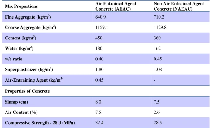
Table 1: Composition and concrete properties
Mix Proportions Air Entrained Agent
Concrete (AEAC)
Non Air Entrained Agent Concrete (NAEAC)
Fine Aggregate (kg/m3) 640.9 710.2
Coarse Aggregate (kg/m3) 1159.1 1129.8
Cement (kg/m3) 450 360
Water (kg/m3) 180 162
w/c ratio 0.40 0.45
Superplasticizer (kg/m3) 1.80 1.08
Air-Entraining Agent (kg/m3) 0.45 -
Properties of Concrete
Slump (cm) 8.0 7.5
Air Content (%) 7.5 2.6
Compressive Strength - 28 d (MPa) 32.4 28.5
2.2 Description of the testing procedure
From each mixture, five specimens were tested for scaling resistance. The concrete specimens with a surface area of 150 x 150 mm2 and thickness of 70 mm were demoulded after 24 hr, cured and exposed to the freeze-thaw test, according to the technical specification UNE-CEN/TS 12390-9 EX - Alternative Method (UNE-CEN/TS 12390-9 EX, 2008).
Before starting the cycles, the specimens needed a special preparation that consisted in four steps: stored for 6 days at 20 ± 2 ºC in water, dry storage in a climatic chamber (20 ºC / 65% RH) during 21 days for surface drying; before at the age of 28 days, the specimens were sealed on the lateral surfaces with epoxy resin. After the dry storage, the specimens were placed for 7 days in the test containers with the test surface on the bottom for pre-saturation of test liquid by capillary suction. At the age of 35 days, the specimens were ready to be exposed to the cycles. A 12 h freeze-thaw cycle in which temperature varied between +20 and -20 ºC was applied starting at +20 ºC (Figure 1a).
a) -30 -20 -10 0 10 20 30
0 1 2 3 4 5 6 7 8 9 10 11 12
T
e
mp
e
rat
ur
e (º
C
)
Time (h)
b)
The test was performed with standard de-icing agent solution, 97% by weight of distilled water and 3% by weight of NaCl. The surface deterioration was measured by weighting after 4, 6, 14 and 28 FTC. Before each measurement, loosely adhering particles were removed from the surfaces of the specimens by treatment by ultrasonic bath. Then the scaling particles were collected and dried for 24 h at 100 ºC. After cooling, the weights of the scaled particles were measured.
2.3 Non-destructive test measurements
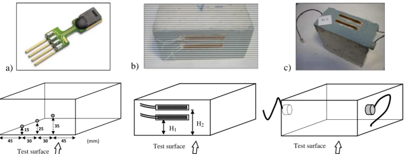
For temperature and humidity measurements inside the concrete prisms, during the concrete cast, digital humidity sensors were embedded in each specimen. The measurements were taken continuously during all the FTC in each prism specimen using three sensors placed 40 mm inside the concrete at different heights from the surface in contact with the test liquid (Figure 2a).
The superficial strain of the prism concrete samples, during the freeze-thaw cycles was measured using two commercial strain gages by specimen, which were glued with an adhesive in the middle and
upper part of the lateral surface of the specimens as shown in Figure 2b (H1= 30 mm y H2= 55 mm).
A double zero crossing algorithm (Hernández et al., 2006) was used to know the travelling time of the ultrasonic signal and then the ultrasonic pulse velocity (UPV) was established. For each concrete specimen two longitudinal wave transducers (500 kHz) were glued directly to the surface of the concrete prisms. The position of the transducers is shown in Figure 2c. The internal damage has been
studied by the Relative Dynamic Modulus of Elasticity of concrete (RUPTT), calculated using the
Ultrasonic Pulse Transmission Time (UPTT) measurements, according to the RILEM TC 176-IDC standard (RILEM TC 176-IDC, 2004).
a) b) c)
Figure 2: Sensors used for NTD measurements in concrete prisms subjected to Freeze-thaw cycles:
a) Temperature & humidity, b) Strain gauges, c) Ultrasonic transducers
3. Experimental results and analysis
3.1 Loss of weigh – Scaling
The results of scaling are shown in Fig. 3a. According to the freeze-thaw resistance test, the failure of the non air-entraining admixture concrete (NAEAC) occurred before 28 freeze-thaw cycles, the
cumulative amount of scaling of 1.5 kg/m2 was near to the 17th FTC. In contrast to that, the scaling of
the air-entraining admixture concrete (AEAC) was only 0.10 kg/m2 after 28 cycles, in comparison
with 3.23 kg/m2 in the deteriorated concrete, at the same time. The concrete test surfaces in contact
with the de-icing agent solution of some specimens of both concretes before the test, after 14 and 28 FTC, are shown in Figure 3b-d. Salt scaling is often observed with the exposure of coarse aggregate.
Test surface
45 30 30 45
15 25 35
(mm)
Test surface Test surface H2
H1
a) 0,0 0,5 1,0 1,5 2,0 2,5 3,0 3,5 4,0
0 5 10 15 20 25 30
AEAC
NAEAC
1,5 kg/m2
Sc
al
in
g (
k
g
/m
2)
Number of Freeze-thaw Cycles 0,05
0,88
3,23
0,04 0,10
0,10 0,01
Air-entrained admixture concrete
(AEAC) Non Air-entrained admixture concrete
(NAEAC)
b) c)
d) e)
Figure 3: Freeze-thaw test. a) Cumulative scaling. Photographs of test surface of concrete slabs during the FTC: b) AEAC before the test, c) AEAC after 28 FTC, d) NAEAC before the test, e) NAEAC after 28 FTC.
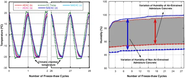
3.2 Temperature and Humidity
The temperature in the climate chamber and inside the specimens for the first two and the last two FTC are shown in Figure 4a. The temperature in both concretes was almost the same. Moreover, the temperature variations at different locations inside the specimen were negligible. Thermal inertia was observed between the surface and inside the concrete specimens. The maximum and minimum humidity inside the specimens of both concretes during the FTC are shown in Figure 4b. In NAEAC the range of humidity variation was higher than in AEAC, even the total saturation of the NAEAC specimen was achieved after the 21st FTC.
-30 -20 -10 0 10 20 30
0 1 2 26 27 28
AEAC (b) AEAC (a)
CC Temp
NAEAC (d)
NAEAC (c)
T
e
m
p
e
ra
tur
e
(º
C
)
Number of Freeze-thaw Cycles Climatic chamber
temperature
80 85 90 95 100 105
3 6 9 12 15 18 21 24 27
Hu
mi
d
it
y
(
%
)
Number of Freeze-thaw Cycles Variation of Humidity of Non Air-Entrained
Admixture Concrete
Variation of Humidity of Air-Entrained Admixture Concrete
Figure 4: a) Temperature inside the specimens b) Maximum and minimum humidity inside the specimens.
3.3 Strain measurements
The strains measurements are shown in Figure 5a. The residual strain in the middle part of the
NAEAC after 28 FTC was 1150 m/m, in comparison with only 65 m/m in the AEAC. In NAEAC,
the residual strain measured in the middle part of the prism was quite higher than the 800 m/m of the
temperature rises above -15 ºC, the strain increases and concrete expands until the end of the cycle. The positive strain continues until the temperature is under 5 ºC in the next cycle, and it will contract again with the cooling. In the NAEAC specimen, the strain increases progressively with the number of cycles generating residual strains. This behavior is according to the theories that explain the phenomenon and with the results that have been reported that residual strains have been shown to increase progressively with the progress of deterioration (Bishnoi and Uomoto, 2008; Jacobsen et al., 2008; Penttala, 1998; Penttala and Al-Neshawy, 2002).
a) -400 -200 0 200 400 600 800 1000 1200
0 4 8 12 16 20 24 28
NAEAC (Middle) NAEAC (Up) AEAC (Middle) AEAC (Up) S tr a in ( m/m )
Number of Freeze-thaw Cycles Air-entrained Admixture Concrete (Up)
Air-entrained Admixture Concrete (Middle) Non Air-entrained Admixture
Concrete (Middle)
Non Air-entrained Admixture Concrete (Up)
b) -300 -200 -100 0 100 200 300 400
-25 -20 -15 -10 -5 0 5 10 15 20 25
1st Cycle - Freezing 1st Cycle - Thawing 2nd Cycle Freezing 2nd Cycle Thawing
3rd Cycle - Freezing 3rd Cycle - Thawing
4th Cycle - Freezing 4th Cycle - Thawing
Str a in ( m/ m)
Climatic Chamber Temperature (ºC) 1st Cycle 4th Cycle 1st Cycle 4th Cycle Thawing Freezing R e s id ual st ra in
Figure 5: Strains measurements a) Strains of concrete samples during 28 Freeze-thaw cycles, b) Strains values of NAEAC against temperature during first four Freeze-thaw cycles
3.4 Ultrasonic pulse velocity
The ultrasonic pulse velocity (UPV) measured in both concrete specimens in each cycle at the end of the freezing, while the temperature is lowest (-20 ºC) is shown in Figure 6a. The UPV is increased as the exposure to FTC. These could be as result of ice formed inside the specimens due freeze of water porous, like is know that the UPV is higher in ice than in water or air (Kaufmann, 2004). Also, in the same figure is observed that UPV of NAEAC is higher than UPV measured in AEAC. This is because the inclusion of air-entraining agent generates air bubbles, causing a decrease of the UPV, as result of the lower density of the medium of propagation. The UPV measured in both concrete specimens in each cycle at the end of the thawing, while the temperature is highest (+20 ºC), is decreased as the exposure to FTC. This may be related to the increased porosity of the material, because with increasing porosity, decreases UPV (Lafhaj et al., 2006). The decrease in UPV can also be related to
the formation of micro-cracks inside the concrete. The RUPTT is shown in Figure 6b. The RUPTT value
decrease over the FTC in both concretes, which is evidence of internal deterioration of concrete. The
loss in RUPTT is higher in NAEAC compared with AEAC specimens.
a) 4,1 4,2 4,3 4,4 4,5 4,6 4,7 4,8 4,9
0 5 10 15 20 25 30
U lt ra s o n ic Pu ls e Ve lo c it y ( k m /s )
Number of Freeze-thaw Cycles
Air-entrained Admixture Concrete (AEAC) Non Air-entrained Admixture
Concrete (NAEAC)
Min. Temp. (Freezing)
Max. Temp. (Thawing)
b) 94 95 96 97 98 99 100
0 5 10 15 20 25 30
RUP
T
T
(%
)
Number of Freeze-thaw Cycles
Air-Entrained Admixture Concrete (AEAC)
Non Air-Entrained Admixture Concrete (NAEAC)
Figure 6: a) UPV during FTC. At the end of freezing (Min. Temp) and at the end of thawing (Max. Temp)
4. Conclusions
The damage caused by the freeze-thaw cycles in the AEAC prisms was negligible compared with the deterioration of the NAEAC specimens. The resistance of concrete to freezing and thawing is significantly improved by the use of intentionally entrained air, which is confirmed by the results of scaling test and the continuously measurement of strain and Ultrasonic Pulse Velocity.
Strain as a measurement of length changes is an indicator of freeze-thaw concrete deterioration. The residual strain increased when a high degree of saturation is reached and the expansion of ice dominates during cooling and its contraction due to melting ice during heating. The use of commercial strain gages was verified and results showed that it is a reliable, easily and simply method that could supplement or even replace the conventional scaling measures, which corresponding to an awkward procedure.
According to Figure 4b, there is a greater amount of water inside the NAEAC specimen in comparison to AEAC specimen. This conclusion should be carefully considered since the w/c ratio in both concretes is different (0.40 for AEAC and 0.45 for NAEAC).
The measured differences of UPV of concretes specimens before and after 28 freeze-thaw cycles were very small. That means that 28 freeze-thaw cycles according to the UNE-CENT/TS 12390-9 test, do not lead to considerable internal damage of tested concretes as have been reported in studies that use a high number of rapid FTC like the ASTM CC 666/C standard.
5. References
- Bishnoi, S. and Uomoto, T. 2008, "Strain–temperature hysteresis in concrete under cyclic freeze–thaw
conditions", Cement and Concrete Composites, vol. 30, no. 5, pp. 374-380.
- Fagerlund, G. 1977, "The international cooperative test of the critical degree of saturation method of
assessing the freeze/thaw resistance of concrete", Materials and Structures, vol. 10, no. 4, pp. 231.
- Hernández, M.G., Anaya, J.J., Sanchez, T. and Segura, I. 2006, "Porosity estimation of aged mortar using
a micromechanical model", Ultrasonics, vol. 44, no. Supplement 1, pp. e1007-e1011.
- Jacobsen, S., Lindgård, J. and Fritz, L. 2008, "Frost dilation measurements on concrete cores from a dam
with ASR", 13th ICAAR Conference Proceedings, pp. 131.
- Kaufmann, J.P. 2004, "Experimental identification of ice formation in small concrete pores", Cement and
Concrete Research, vol. 34, no. 8, pp. 1421-1427.
- Lafhaj, Z., Goueygou, M., Djerbi, A. and Kaczmarek, M. 2006, "Correlation between porosity, permeability and ultrasonic parameters of mortar with variable water / cement ratio and water content",
Cement and Concrete Research, vol. 36, no. 4, pp. 625-633.
- Penttala, V. 1998, "Freezing-induced strains and pressures in wet porous materials and especially in
concrete mortar", Advanced Cement Based Materials, vol. 7, pp. 8.
- Penttala, V. and Al-Neshawy, F. 2002, "Stress and strain state of concrete during freezing and thawing
cycles", Cement and Concrete Research, vol. 32, no. 9, pp. 1407-1420.
- Powers, T. & Helmuth, R. 1953, "Theory of volume changes in hardened Portland cement pastes during
freezing", Proceedings of Highway Research Board, vol. 32, pp. 285.
- Pigeon, M. and Pleu, R. 1995, Durability of concrete in cold climates, London: E & FN Spon.
- RILEM TC 176-IDC. 2004, Final Recommendation of RILEM TC 176-IDC 'Internal Damage of
Concrete due to frost action' Test methods of frost resistance of concrete: Slab test: Freeze/thaw resistance of concrete - Internal deterioration, RILEM Publications SARL.
- Setzer, M.J. 2001, "Micro-Ice-Lens Formation in Porous Solid", Journal of colloid and interface science,
vol. 243, no. 1, pp. 193-201.
- UNE‐CEN/TS 12390‐9 EX. 2008, Ensayos de hormigón endurecido. Parte 9: Resistencia al
hielo-deshielo. Pérdida de masa superficial, Asociación Española de Normalización y Certificación (AENOR), Madrid, España.
- Valenza, J. and Scherer, G. 2007, "A review of salt scaling: II. Mechanisms", Cement and Concrete