Advanced PV modules inspection using
multirotor UAV
CONFERENCE PAPER
· SEPTEMBER 2015
READS
131
5 AUTHORS
, INCLUDING:
Jonathan Leloux
Universidad Politécnica de Madrid
42
PUBLICATIONS
115CITATIONS
SEE PROFILEL. Narvarte
Universidad Politécnica de Madrid
53
PUBLICATIONS
297CITATIONS
SEE PROFILE1
Advanced PV modules inspection using multirotor UAV
N. Tyutyundzhiev(1)*,K.Lovchinov(1)
,
F. Martínez-Moreno(2), J. Leloux(2), L. Narvarte(2)(1)Central Laboratory of Solar Energy and New Energy Sources (CLSENES) 72 Tzarigradsko chausse Blvd. Sofia. Bulgaria
and Sunwings Ltd.
(2)Instituto de Energía Solar – Universidad Politécnica de Madrid. Grupo de Sistemas Fotovoltaicos (IES-UPM) Campus Sur UPM. Ctra. Valencia km. 7. EUIT Telecomunicación. 28031 Madrid, Spain
*Corresponding author: [email protected]
ABSTRACT: Large-scale PV fields are a complicated target for monitoring and performance evaluation. In this paper, field experience with multirotor UAV has been reported. A X-frame quadcopter equipped with various VIS and IR cameras is used to detect defects responsible for performance degradation. Usually in laboratory environment, hi-res VIS photos, EL photos and far- IR photos of single module are used for diagnostic purposes. However, on-field PV plant testing procedures need faster methods for batch processing. Our investigations confirm that new robotics and avionics equipment for close-range flights over PV modules combined with cameras can reveal hidden problems of materials quality and device reliability. Various new tasks, as high resolution aerial photography, 3D photogrammetry, 3D field and building reconstruction can be involved as testing methods for performance optimization of photovoltaic installations.
Keywords: PV module inspection, Infrared imaging, 3D photomapping, multirotor UAV
1. INTRODUCTION
Large-scale PV fields are a complicated target for monitoring and performance evaluation [1],[2],[3]. Recent ideas, how to accelerate testing process are focused on open-source flying platforms, known as micro UAV [4],[5]. X-frame quadcopters equipped with various VIS and IR cameras are new attractive tools for fast detection of defects responsible for performance degradation. On the other hand, design, assembling and construction of UAV became popular due to fast-growing open-source information and low prices of components. Discussions and exchange of practical experience in forums further accelerate the dissemination of good practices. In solar research sector these new opportunities can be applied for advanced instrumentation preparation for on-field PV testing.
Aerial photomapping is well-developed satellite technology but for low-altitude, low-budget autonomous flying platforms it is still a challenge [6], [7], [8]. It has become much easier to capture, scan and process images and 3-D scenes from the air with light-weight cameras and electronics. It is no longer needs to hire airplane or deltaplane to take aerial photos because the scene can be shot with UAV at various heights, with more flexibility and reduced cost.
2. LOW-ALTITUDE FLIGHT INSPECTION – visual and infrared
2.1Equipment
The IR cameras manufacturers drastically have reduced the price and opened the firmware for IR sensors enthusiasts. Now, SDK libraries and IR sensor boards for AppleOS and AndroidOS became attractive for UAV applications [9], including IR inspection of PV modules. Our testing IR board is based on several low-cost IR cameras and FLIR sensor for I-phone5 attachment.
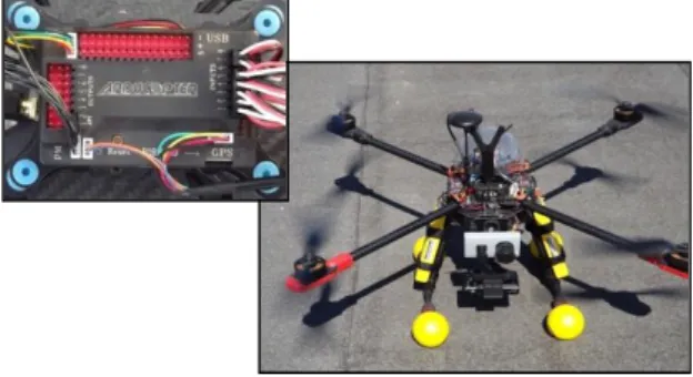
Figure 1: PV drone 2 based on open-source “ArduCopter” software.
The quadcopter shown at Fig.1, is assembled from low-cost parts. It consists of X-shaped 850 mm carbon frame, 250W DC motors, 13” carbon propellers. It can carry 1.5kg additional payload: -cameras, transmitter, 2.4GHz RC .
Based on open–source tools, our quadrotor UAV is designed for autonomous flights with the capability of videostream transferring to Ground Control Station and IR still-pictures shooting. Sensors on-board the quadrotor UAV are 3-axis gyros, accelerometers, 3-axis magnetometer, barometer and a single channel GPS receiver.
2 As can be seen at Fig.2 the expected mixed flight
time is 16.9 min when a 5 000 mAh LiPo battery is used. The advantage of the proposed tool is a possibility to inspect PV plants in Vis, near-IR and IR ranges and to detect failures.
2.2Flight controller tuning
The mechanical construction of rigid, low-weight frame for UAV using carbon sheets and tubes has numerous variations and solutions. Problem arises when 3-D dynamics equations have to be satisfied by proper calculation of driving forces from 4, 6 or 8 DC motors. The flight sensors – accelerometer, compass, barometer, GPS sensor and PID controller loop feedback have to be precisely tuned in order multicopter “hover” to be obtained. The requirements for good aerial photos preparation using UAV are: stable “hover” up to 10 m above PV plant; radio control and image triggering; 1-2 kg payload; 15-30 min flying time. Before every flight mission, PID parameters have to be adjusted depending on payload, balance and air conditions- air density, humidity, wind flow. In our
Figure 3: PID controller tuning [11].
PID controller parameters are 3 variables which permit error compensation; It automatically compensates and adjusts DC motors rotation to provide flight stability. Tuning is essential for a perfect flight and image acquisition. All 3 variables react to stick inputs of radio control board and the errors created by measurements from the flying sensors. Fig.3 presents our flight stability solution.We need to find a balance. Proper tuning means very solid in the air, no oscillations of the frame, fast reaction to stick movement. The last little tune is performed in the air by sending parameters adjust with telemetry.
2.3Flight inspection results
The low resolution and simple optics of our IR cameras restrict the distance and respectively the flight height above investigated object. Our field practice, explained elsewhere [12], reveals that 15 cm x 15 cm “hot spot” in poly-Si solar cell can be recognized from up to 5 m distance. As can be seen at Fig.4 the temperature rise in the center of “hot spot” during bright sunny day (GHI > 700W/m2) is 25 -30oC above the neighboring cells.
High temperature differences of 15-20oC are observed in shaded areas as well (Fig.5). Those PV strings affected by shading should be protected using power optimizers.
Figure 4: IR images of “hot spots” in PV modules detected by PV drone 2
3 3. UAV PHOTOMAPPING
3.1On-board electronics for UAV photomapping In our experiments, down-looking 16Mpx hi-res photo camera is configured for photomapping purposes. Radio controlled intervalometer performs triggering every 4 sec. and controls timing of the camera. The series of pictures are stitched later using PhotoScan software.
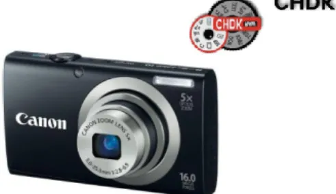
The used Canon IXUS 135 IS, Digic 4 processor, depicted in Fig.6, is a consumer camera at a nominal focal length of 5.90mm and weight of 132 g. It features a 1/2.3” CCD which corresponds to a CCD sensor size of 4.64x6.18mm with 1.54x1.54 μm² pixel size each, which provides images of 3456 x 4608 pixel. The camera is triggered from the on-board computer via the camera USB interface in combination with an Arduino Mini intervalometer and CHDK firmware. MiniArduino board is programmed to control the production of successive series of photos during linear flight of our multirotor UAV.
Figure 6: Compact Canon camera controlled by CHDK script
3.2Intervalometer for automatic triggering
The camera shutter needs to be triggered throughout flying mission at regular time intervals. If Canon compact camera is used (for example IXUS 135), a model supported by the CHDK software, this device allows you to take off your UAV with camera lens safely retracted. When you are in a position to take images, rotate a knob on your RC transmitter and the camera comes alive. It extends the lens and starts taking pictures at an interval you’ve specified. It is essential in the case of a multirotor setup where the camera is facing straight down beneath the quadrotor and susceptible to blown dirt from the rotor blast.
AnArduino Mini328 is programmed to monitor the PWM signal coming out of the aircraft’s RC receiver and to send 3 commands to the camera depending on the position of analog knob of the RC transmitter. The Canon camera is operating with the CHDK software and running a script which watches the signals coming in on the USB port. In the analog knob “left position” the camera stands in standby, in “middle position”- it begins taking pictures at rapid intervals, while in the “right position” – it shuts itself down and close the lenses.
3.3Photomapping preparation
After landing, the raw photos are loaded in image post-processing software which transforms photos to ortho-photos and generates hi-res close-range map. It is difficult to model complex shaped roofs and to recreate complex object appearance using standard models. Not surprisingly, image-based techniques to create 3D models automatically by scanning real objects have
been greatly developed. The requirements to cameras for photomapping are related to image distortion at the edges due to aperture angle of the optics. Wide aperture action cameras are not suitable for image stitching due to significant “fish-eye” effect of their lenses. A compact 16 Mpx camera, Canon IXUS with an integrated zoom lens, is an acceptable device for image acquisition related to - lightweight and features [13]. The shorter exposure times of the camera minimizes the risk of motion blur which can cause noise in the image features.
The UAV system is capable of doing fully automatic flights along commanded waypoints including automatic take-off and landing. The UAV can also be monitored and commanded by a PC based ground station which is connected via RF link.
3.4Image processing procedure
The pipeline of the process includes flight planning, image acquisition and image post-processing. The photos are arranged and oriented automatically according to similarity in details. Then, a dense surface 3D model is generated. General sequence of the process is preparation of Aerial photo – Ortho correction – Orthophoto - 3D model. An automated matching procedure for invariant points in images is applied in several steps. The overlapping in adjacent images is important factor which reduces mismatching and optical noise. Thus, the software creates 3-D visibility map in shorter computational time.
3.5Photomapping experiment
The experimental testing phase involved the carrying out of multirotor UAV slow-running flights around PV rooftop installation with capacity of 190 kWp in a valley area free from high vegetation and mountain hills. Ground station software is used to manage waypoint lists and to monitor the multirotor UAV during flight. For waypoints, UTM coordinates or relative coordinates to the starting point can be loaded before or during operation. The IMU controller guides the UAV on the connection line between two adjacent waypoints.
In fact, a good software rendering can be accomplished with 50-100 images [14]. More than 50% overlapping between sequential images is recommended to ensure quality in image processing. Max 40 m above building is sufficient for good 3-D map generation. The flying mission should include slow UAV flight in parallel tracks close enough to perform 50% overlap of images [15]. Base/Height ratio is a measure of overlap, it has to be adjusted in the range of 0.25-0.35.
In order to evaluate the capability and efficiency of UAV-based photogrammetric data collection, test flights were performed at PV roof test site. According to flight planning, the area was covered with two flights at 3 flight-lines for a period of 10 min.The total amount of acquired aereal images exceed 180 pcs. Then 103 of them have been used for 3-D modeling. During the second flight strong wind has increased the power consumption of the UAV and has reduced the flight time to 8 min.
3.6Photomapping results and discussion
4 tools for the generation of tie (invariant) points.
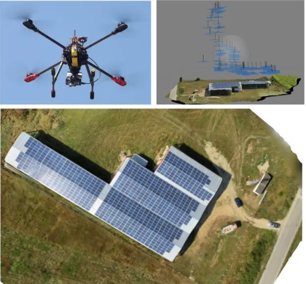
Figure 7: Aerial photomapping of PV rooftop using quadrotor UAV
Primitives suitable for image matching are extracted in a first step, while in a second step their correspondences are determined by some similarity and consistency measures.
In order to illustrate the systematic image preparation and the real-time changes in terrain more clearly, a ortho-photo images were generated based on the results from the flights using the PhotoScan software installed on Windows PC. Fig. 7 shows the PV drone, image acquisition process and 3-D scene of the PV roof test area obtained from aerial images. The blue shapes are the camera positions. The altitude of flights for image acquisition varies from 10 to 40 m. Most of the images are crisp which helps with feature detection and matching.
Two aspects of the results are worthy to note - sunlight reflection from roof surfaces and image resolution relative to altitude.
The observed feature of the software 3-D modeling is significant variation in quality of 3-D image depending on sunlight reflection from PV modules observed in some of the aerial 2-D images. As can be seen on Figure 8, bright reflections from the glass surfaces cause “white spots” in the images, loss of contrast and distortion in the generated surface mesh. These findings imply that most suitable days for image acquisition without reflections are cloudy days with no
direct sunlight or in late afternoons when the angle of reflection is small and the effect is negligible.
Taking photos at higher altitude is an attractive approach in order to collect more image blocks and large primitives. It will facilitate more of the scene to be captured in fewer photos but with lower ground resolution. At lower altitude the resolution increases but on account of more photos and processing time. Image distortion is also much more affected at lower distances. The software is much more sensitive to small details variation than to flat surfaces which results in additional image distortions after the automated matching procedure. Some experimentation may be required in order to determine the best configuration depending on the task – detection of defects in PV modules or shade analysis of building roofs.
5 Figure 8:Image distortion in 3-D scene caused
by sunlight reflection
4. CONCLUSIONS
New approaches for contactless inspection of large area PV fields have been investigated. Aerial inspection of PV installation using multirotor UAV is demonstrated. Infrared imaging and aerial photo-mapping technologies are applied for PV rooftop visual inspection. The experiments confirm that numerous low cost, light-weight video and still-picture cameras are suitable devices for FPV (First Pilot View), IR image acquisition and image photomapping based on low altitude flights with micro UAV.
This also demonstrates that despite some remaining problems in absolute accuracy, standard mapping products like PhotoScan, PhotoModeller, etc. are useful tools for reconstruction of 3-D images of PV plants or PV rooftop systems. High-res images can be generated very well from UAV imagery. Recent aerial technologies are ready to be used in PV testing procedures.
ACKNOWLEDGMENTS
This work was supported by the European Commission, under the terms of Seventh Framework Programme, in the context of the PVCROPS project (PhotoVoltaic Cost r€duction, Reliability, Operational performance, Prediction and Simulation), contract No. 308468 [16].
REFERENCES
[1] Martínez-Moreno F., Lorenzo E., Muñoz J., Parra R., Espino T. On-site tests for the detection of potential induced degradation in modules. 28th European Photovoltaic Solar Energy Conference: 3313-3317. (2013).
[2] Leloux J., Narvarte L., Luna A., Desportes A. Automatic detection of PV systems failures from
monitoring validated on 10,000 BiPV systems in Europe. 28th European Photovoltaic Solar Energy Conference. (2013).
[3] Moretón R., Lorenzo E., Leloux J., Carrillo JM. Dealing in practice with hot-spots. 29th European Photovoltaic Solar Energy Conference. (2014). [4] Aghaei M., Bellezza Quarter P., Grimaccia F.,
Leva S., Mussetta M. Unmanned aerial vehicles in Photovoltaic systems monitoring applications 29th European Photovoltaic Solar Energy Conference. (2014).
[5] Buerhop C., Scheuerpflug H. Field inspection of PV-modules using aerial, drone-mounted thermography. 29th European Photovoltaic Solar Energy Conference.2975 (2014).
[6] Lorenz M., Tanskanen P., Heng L., Lee G. H., Fraundorfer F., Pollefeys M.. Pixhawk: A micro aerial vehicle design for autonomous flight using onboard computer vision. Auton. Robots, 33(1-2):21–39, (2012).
[7] Saurav Agarwal,Monocular Vision Based Indoor Simultaneous Localisation and Mapping for Quadrotor Platform, MSc thesis, Cranfield University, Bedfordshire, UK (2012).
[8] Lian Pin Koh and Serge A. Wich, Dawn of drone ecology: low-cost autonomous aerial vehicles for conservation
,
Tropical Conservation Science Vol.5 (2),121-132 (2012).[9] Navarro M. Quick start guide for Raspberry Pi 2 and FLIR Lepton, internet source:
http://GroupGets.com (June 2015).
[10] Mueller M. xcopterCalc - Multicopter Calculator,
internet source: http://ecalc.ch/xcoptercalc.php (July 2015).
[11] Dave C. Arducopter Tuning Guide, internet source: http://diydrones.com Nov (2012). [12] Tyutyundzhiev N., Martínez-Moreno F, Leloux
J., Narvarte L. Equipment and procedures for on-site testing of PV plants and BiPV 29th European Photovoltaic Solar Energy Conference. (2014). [13] Leinss B., Analyse zweier Kameras für die
UAS-Luftbilderfassung, Universität Stuttgart – iFR, thesis, June (2014).
[14] Mesas-Carrascosa F.J., Rumbao I.C., Berrocal J., Porras A., Positional Quality Assessment of Orthophotos Obtained from Sensors Onboard Multi-Rotor UAV Platforms, Sensors, vol. 14, 22394-22407, (2014).
[15] Sadikin H., SaptariA., Abdulharis R., Hernandi A.,
UAV System With Terrestrial
Geo-refferencing For Small Area Mapping, FIG Congress 2014, Engaging the Challenges – Enhancing the Relevance, Kuala Lumpur, 7146 (2014)
![Figure 3: PID controller tuning [11]. PID controller parameters are 3 variables which permit error compensation; It automatically compensates and adjusts DC motors rotation to provide flight stability](https://thumb-us.123doks.com/thumbv2/123dok_es/6787280.832050/3.892.467.762.204.649/controller-controller-parameters-variables-compensation-automatically-compensates-stability.webp)