Biomechanics of smart wings in a bat robot: morphing wings using SMA actuators
This article has been downloaded from IOPscience. Please scroll down to see the full text article.
2012 Bioinspir. Biomim. 7 036006
(http://iopscience.iop.org/1748-3190/7/3/036006)
Download details:
IP Address: 138.100.76.136
The article was downloaded on 26/04/2012 at 11:59
Please note that terms and conditions apply.
View the table of contents for this issue, or go to the journal homepage for more
IOP PUBLISHING BIOINSPIRATION& BIOMIMETICS
Bioinspir. Biomim.7(2012) 036006 (16pp) doi:10.1088/1748-3182/7/3/036006
Biomechanics of smart wings in a
bat robot: morphing wings using
SMA actuators
J Colorado
1, A Barrientos
1, C Rossi
1and K S Breuer
21Centre for Automation and Robotics, Universidad Polit´ecnica de Madrid, Madrid, Spain 2School of Engineering, Brown University, Providence, RI 02912, USA
E-mail:[email protected]
Received 7 October 2011
Accepted for publication 27 February 2012 Published 26 April 2012
Online atstacks.iop.org/BB/7/036006
Abstract
This paper presents the design of a bat-like micro aerial vehicle with actuated morphing wings. NiTi shape memory alloys (SMAs) acting as artificial biceps and triceps muscles are used for mimicking the morphing wing mechanism of the bat flight apparatus. Our objective is twofold. Firstly, we have implemented a control architecture that allows an accurate and fast SMA actuation. This control makes use of the electrical resistance measurements of SMAs to adjust morphing wing motions. Secondly, the feasibility of using SMA actuation technology is evaluated for the application at hand. To this purpose, experiments are conducted to analyze the control performance in terms of nominal and overloaded operation modes of the SMAs. This analysis includes: (i)inertial forcesregarding the stretchable wing membrane and aerodynamic loads, and (ii)uncertaintiesdue to impact of airflow conditions over the
resistance–motion relationship of SMAs. With the proposed control, morphing actuation speed can be increased up to 2.5 Hz, being sufficient to generate lift forces at a cruising speed of 5 m s−1.
(Some figures may appear in colour only in the online journal)
1. Introduction
Bats have evolved with powerful muscles that provide the morphing capability of their wings, i.e. folding and extension of the wings during flight. To change wing morphology, bat wings are made of flexible bones that possess independently controllable joints [1], and a highly anisotropic wing membrane containing tiny muscles that control the membrane tension [2]. This high degree of control over the changing shape of the wing has a great impact into the maneuverability of the animal [3–5].
To closely mimic the morphing wing mechanism of bats, muscle-like actuation seems to be an adequate solution. In this regard, shape memory alloys (SMAs) have opened new alternatives with the potential for building lighter and smaller smart actuation systems [6–10]. To the best of the authors’ knowledge, the only works attempting to reproduce bio-inspired bat flight using SMAs are presented in [11] and
[12]. A robotic platform called BATMAV (fully actuated by SMA wires) is described in both papers. Thereby, SMAs have been used for two purposes: first, as muscle-like actuators that provide the flapping and morphing wingbeat motions of the bat robot, and second, as super-elastic flexible hinges that join the wing’s bone structure. Most of the experiments in [11] were carried out with a two degree of freedom wing capable of flapping at 3 Hz. Despite the fact that their robot is able to achieve accurate bio-inspired trajectories, the results presented lack experimental evidence of aerodynamics measurements that might demonstrate the viability of their proposed design. Moreover, neither [11] nor [12] detail how to control the SMAs to achieve the bio-inspired motion of BATMAV’s wings.
The current work is oriented toward the development of a novel biologically inspired bat aerial robot with morphing wings actuated by SMA-based artificial muscles (see figure1). Our goal is to control these muscles to achieve morphing wing trajectories based on the biological study of bat flight
Plagiopatagium skin (0.1mm silicon wing membrane)
R/C transmission link 49MHz Antenna
Steel tendons
III
IV V II
I
servo+ electronics
SMA morphing muscles
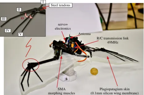
Figure 1.Actuation mechanisms: (i) four SMA-muscles (supplied by Migamotors) of 1.1 g that provide the morphing wing motion, (ii) one servo motor of 8g that provides the flapping-wing motion. Electronics onboard: (i) arduino-based board+IMU (6 g), (ii) four
MOSFET-boards to power the SMA artificial muscles (4 g), (iii) 49 MHz receiver (2 g), and (iv) LiPo battery of 30 g. The overall weight of the skeleton+electronics is 79 g (without battery).
presented in [1,14] and [15,17,18]. The bat robot features a hybrid drive, partially actuated by a servo motor which drives the primary flapping motion, and SMA actuators (Migamotor nanomuscles [13]) which drive the morphing-wing motion. Here, we have focused on the latter, by: (i) implementing a robust control architecture that allows for an accurate SMA-muscle actuation, and (ii) validating through aerodynamics experiments that our morphing wing approach contributes to an increased lift force during the wing’s downstroke and reducing drag during upstroke.
In terms of SMA control, Yee et al [19, 20] studied different phenomena on NiTi SMA wires, from small-signal high frequency response analysis, to force models based on system identification, and the proper mechanisms that allow for faster and accurate force control of an antagonistic pair of SMA actuators. These mechanisms are called (i) anti-slack and (ii) anti-overload. The former deals with the two-way shape memory effect [21], improving accuracy and speed, whereas the latter limits the amount of input heating power to prevent physical damage when SMAs are overloaded. As a result, their force controller was capable of tracking fast and accurate force references when compared with other approaches reported in the literature [22–24]. Nonetheless, their control architecture requires high-bandwidth force sensors capable of providing the force feedback.
Here, we have implemented a control architecture similar to the one described in [20], which makes use of both anti-slack and anti-overload mechanisms to manage the aforementioned limitations in SMA actuation speed and accuracy. However, we propose some important changes to the architecture motivated by the fact that the available payload capacity of our robot limits the use of force sensors. Instead, SMA electrical resistance feedback is used to sense motion [25,26]. Thereby, both anti-slack and anti-overload mechanisms have been developed to regulate the amount of input heating
power based on a resistance–motion (RM) relationship (see subsection4.2). Experimental results in section5show proper position control performance in terms of tracking and actuation speed, even under the presence of external disturbances caused by aerodynamics forces and inertial loads produced by the wing’s membrane tension.
2. Biological inspiration
The bat-like robot used in this research (see figure 2) was designed in collaboration with the Breuer Laboratory at Brown University3, and fabricated by the authors in the Robotics and
Cybernetics Group4at the Centre for Automation and Robotics
UPM-CSIC.
Based on the morphology ofPteropus poliocephalu[15], our bat robot is about 50% smaller than the true specimen size. Table1compares morphological parameters between the robot and the specimen. As shown in figure2, the entire skeleton of the bat robot is composed of the body (17 g), two shoulder joints (both weighting 24 g), legs (2 g) and wings (12 g). Each wing is composed of the humerus and radius bone, digits connected to the wrist joint and a silicone-based membrane with a thickness of 0.1 mm.
Each wing of the robot has six degrees of freedom (DoF), two DoF are directly controlled whereas the others are under-actuated. The actuated joints are (i) the shoulder (θ1)5 and
(ii) the elbow (θ3). The angleθ1corresponds to the flapping
motion of the wings, whereas θ3 corresponds to the motion
of the morphing wings (contraction/extension). On the other
3 http://brown.edu/Research/Breuer-Lab/index.html 4 http://www.robcib.etsii.upm.es/
5 The shoulder joint is composed of two DoF:θ
Bioinspir. Biomim.7(2012) 036006 J Coloradoet al
humerus bone radius bone thumb
leg
elbow joint wrist joint
SMA muscles biceps, triceps shoulder joint
wing
membrane MCP-III
MCP-IV
MCP-V
Figure 2.Biologically inspired bat-like robot. The wingspan is 53 cm (wings fully extended). The skeleton has been fabricated using ABS (acrylonitrile butadiene styrene), and the 0.1 mm stretchable membrane made of silicone. The entire robot has 14 DoF (not counting the 6 DoF of the free-floating body). Each wing has six DoF, and the legs attached to the body provide the other two DoF.
3
lh
lr lm/2 lwt
4,5,6
2
1
body(floating base)
z1
z2 z3
z4,5,6
x4
x3 x1
wingtip
y4
y1 y3
y5
y6
x6
z0 = zb
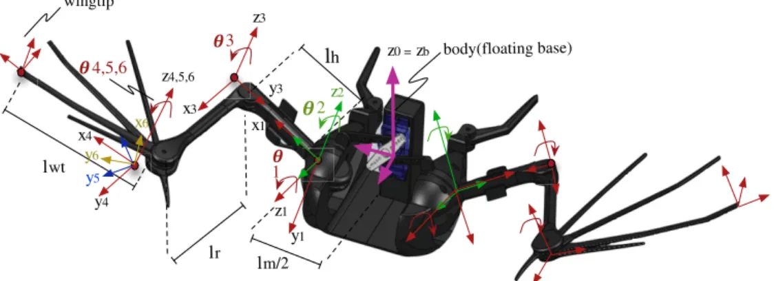
Figure 3.CAD design of the bat robot detailing the kinematics frames of references.
Table 1.Morphological parameters
Parameter (unit) Bata Robot
Total massmt(g) 98 79
Extended wing lengthB(m) 0.462 0.245 Body widthlm(m) 0.07 0.04
Body massmb(g) 41 18
Body inertia tensor diagonal – [1, 0.07, 0]
Ib(gcm2)
Extended wing span 0.99 0.53
S=lm+2B(m)
Extended wing areaAb(m2) 0.069 0.05 Humerus lengthlh(m) 0.11 0.055 Humerus average diameter 2rh(m) 0.0055 0.006
Humerus inertia tensor diag. – [0.03, 0.37, 0.93]
Jh,cm(gcm2)
Humerus position vector to – [0.0275, 0, 0] CMsh,cm(m)
Radius lengthlr(m) 0.145 0.070 Radius average diameter 2rr(m) 0.0042 0.005
Radius inertia tensor diag.Jr,cm(gcm2) – [0.07, 0.92, 0.37] Radius position vector to CMsr,cm(m) – [0.035, 0, 0] One-wing massmw(g) 16.58 8.2 Plagiopatagium membrane 0.0002 0.0001
thickness (m)
aMorphological parameters of the specimen extracted from [15].
hand, the wrist6 (θ
4) is an under-actuated joint that rotates
as a function of the elbow joint. To connect both joints,
6 The wrist jointθ
4is composed of three DoF: MCP digits III, IV and V.
steel tendons have been placed inside the radius bone, as shown in figure 1. These tendons allow for the motion of the metacarpophalangeal (MCP) digits III, IV and V, which are attached to the wrist joint. Each digit has different radii, allowing for different rotation ranges. Using this approach, the digits open and close to maintain the proper tension of the wing membrane during the motion of the morphing wings. Figure3shows the frames of references of each joint of the robot’s wings.
In terms of actuation, we have decided not to use SMA actuators to drive the primary flapping motion of the wings7. The main reason for this choice concerns the speed limitation of SMAs for achieving higher flapping frequencies. On the other hand, the lighter structure of the SMA actuators make them suitable for the fabrication of lighter wings with similar muscle-like actuation to that in biological bats.
The experiments described in section 5 are conducted to analyze how fast the robot’s wings can be changed using the SMA actuators, and also to determine via aerodynamics measurements if both flapping and morphing wing motions can be synchronized to produce sufficient lifting forces to allow the robot to perform sustained flight.
tendon-like chord attaching the
muscle to the elbow
3
lsma 2rj
SMA_1
SMA_2
-+
I_1 Fsma-1
Fsma-2 dif
I_2
SMA antagonistic model
4 mm of stroke 38.7 mm
SMA wires attached to metal strips
Figure 4.Antagonistic mechanism of SMA-based muscle actuators.
3. Morphing-wings’ biomechanics
3.1. SMA-based artificial muscles
An antagonistic configuration of SMA NiTi muscle-like actuators [13], provides the motion of the morphing-wings, as shown in figure 4. The Migamotor actuator consists of several short strips of SMA wire attached to opposite ends of six metal strips stacked in parallel. Each SMA segment pulls the next strip about 0.67 mm relative to the previous strip and the relative movements sum to make a stroke of 4 mm.
From biological data reported in [14], the elbow’s range of motion typically varies from 10◦ to 90◦. During the downstroke, wings are fully extended in order to maximize the area and increase lift, whereas during the upstroke, wings are folded in order to reduce aerodynamic drag. In our robot, this property has been mimicked by attaching the antagonistic pair of SMA actuators to the elbow, which allow the wings to track a reference trajectory by implementing a proper control methodology. In figure 4, the modules SMA1 and SMA2
represent this antagonistic configuration (artificial biceps and triceps). When one SMA actuator contracts, the generated pull force (Fsma) is transformed into a joint torque (τdif). For the
application at hand, τdif = τθ3 (elbow’s torque). The input
of each muscle corresponds to an electrical current signal, denoted asI1andI2, respectively, which are a direct function of
the input heating powerP(t)=I(t)2R(t), withR(t)denoting the SMA electrical resistance.
Using a kinematics model that relates the elbow’s motion rate (θ˙3) to the SMA strain rate (ε˙), the rotation of the joint
can be calculated using (1), withlsma denoting the length of
the parallel arrangement of SMA wires andrjthe radius of the joint:
˙
θ3=lsmaε(˙ 2rj)−1. (1) Our wing biomechanics design allows an elbow rotation range of about 60◦. In terms of performance, the manufacturer (Migamotors [13]) determines that under nominal operation, one SMA artificial muscle is able to generate a joint torque of τi = 12.12 g cm, requiring an input electrical current of 175 mA at 3 V. Section5.1shows simulation and experimental testing for overloading SMA performance, aiming at improving their nominal output torque and actuation speed.
For instance, a thermo-mechanical model has been used to analyze the performance of the SMAs under simulation. SMAs exhibit a unique thermomechanical property due to the phase transformation of the material, from austenite phase to martensite phase and vice versa. These transformations mainly occur due to changes in temperature and stress. Extensive research has been devoted to modelling these properties. Tanaka in [27] was one of the pioneers to study a stress-induced martensite phase transformation, proposing a unified one-dimensional phenomenological model that makes use of three-state variables to describe that process: temperatureT, strainεand martensite fractionξ. His main contribution was to demonstrate that the rate of stress is a function of strain, temperature and martensite fraction rates. Later, Brinson [28] improved on Tanaka’s model by separating the calculation of the martensite fraction into two parts, one induced by stress and the other induced by temperature. This advance allowed for the description of the shape memory effect at low temperatures.
Elahinia [29,30] proposed an enhanced phenomenologi-cal model compared to the previous ones and also addressed the nonlinear control problem. This model was able to better describe the behavior of SMAs in cases where the temperature and stress states changed simultaneously. Their model was verified against experimental data regarding an SMA actuated robotic arm. As a result, the phenomenological model was also able to predict SMA behavior under complex thermome-chanical loadings. Further experiments were also carried out in [31].
Here, we have used Elahinia’s phenomenological model, which is fully described in [30]. Using this model, the effects of overloading the operation of the SMA actuators are analyzed and discussed in section 5.1. To overload the SMAs, high values of input electrical currents are applied. A summary of the thermomechanical equations are detailed in theappendix.
3.2. The wing membrane
Bioinspir. Biomim.7(2012) 036006 J Coloradoet al
(a) (b)
CL
CD Force sensor
airflow
FL
FD
Figure 5.(a) The elasticity and cambering properties of the 0.1 mm silicone membrane are tested on the wind tunnel. (b) Experimental aerodynamics measurements of liftCLand dragCDcoefficients at different airspeeds: 5 and 10 m s−1, and angles of attack: 0◦to 25◦ (membrane fixed to the robot at mid-downstroke).
and wrinkled texture that flattens out to create a taught airfoil when the wings are extended.
The most important features of the wing membrane to mimic are its stretchable and cambering properties. The membrane should be easily expandable and not present a high-load to the SMA actuators. This property has been achieved by mixing 20 g of two different compounds of liquid soft platinum silicone rubber, resulting in a light and stretchy wing membrane with a thickness of 0.1 mm. Another interesting property concerns the wing cambering during flight. In [16], wing camber has been quantified for several species of biological bats. The results of the study have shown the influence of bat body mass (Mb) not only on the wing camber, but also on the lift production, flight velocity and flapping frequency. Figure 5(J) in [16] shows the wing camber coefficient as a function of body mass. In particular, we have focused on the speciesRousettus aegyptiacus, because of its similar morphological and mass properties compared to our artificial counterpart. In conclusion, wing camber at maximum span is proportional to∝M0.71
b (in our case,Mb=0.079 kg). Therefore, the wing camber of our robot has been empirically adjusted to be about 0.16, similar to the values measured from the biological counterpart (0.14–0.15). Figure 2 in [16] explains the procedure of measuring the mid-downstroke wing camber using an external camera.
On the other hand, we have performed aerodynamics measurements in a wind tunnel to test how the membrane behaves when subject to different airflow speeds. These experimental results are reported in figure 5. Figure 5(a) depicts the testbed, which shows the model mounted in the wind tunnel, on the end of a supporting sting that defines the angle of attack. The robot is mounted on top of a 6-DoF force sensor from which both liftCL and dragCD coefficients are experimentally calculated as a function of the airflow speeds and angle of attack. Typical results are shown in figure5(b).
Both lift (L) and drag (D) force components are calculated using (2); then, the lift and drag coefficients are computed using CL = 2L(ρVair2Ab)−1 and CD = 2D(ρVair2Ab)−1,
respectively. The termρ =1.20 Kg m3is the air density,V air
is the airspeed andAb=0.05 m2is the planform area: L=FLcos(α)−FDsin(α)
D=FDcos(α)+FLsin(α). (2) The tests have empirically shown that the wing membrane has the desired elasticity property, and that the wing camber is about 0.16 at mid-downstroke. Most important, the tests have also demonstrated that using a fixed wing, the robot is not able to generate enough lifting forces. Note that at airspeed of
Vair=5 m s−1and an angle of attack ofα=15◦, the measured maximum lift force was about 0.72 N (CL=1.1), less than the bat robot’s weight force of 0.775 N.
In section 5.3, we demonstrate that lift forces can be increased by flapping, and drag can be reduced thanks to the folding capability of the wings. Our goal is to produce an efficient lift-to-drag ratio within an angle of attack range between 5◦ and 10◦. Furthermore, in section 5.2, we test whether the SMA artificial muscles are strong enough to actuate the wing skeleton with the surface tension and aerodynamic load of the membrane, and how this issue affects the nominal and overloaded operation of the SMAs. Before addressing these issues, the closed-loop control that drives the morphing wing mechanism is introduced in the following section.
4. Morphing wing SMA control
4.1. Control architecture
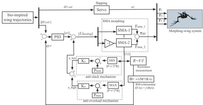
Figure6describes the implemented control architecture. The block—morphing wing system—represents the robot’s wing structure. It receives three inputs: τ1, which is the flapping
torque generated by the servo motor signal u1, and τ3,L,
τ3,R, which correspond to the torques generated by the SMA actuator’s differential torqueτdif. The subscriptsLandRrefer
to the left and right wing, respectively. Likewise, the blocks SMA1and SMA2represent the SMA actuators of both wings,
SMA-1
SMA-2
-+
Fsma_1
Fsma_2
[Uheating]
-1 SMA morphing
R=V/I Resistance measurement
3(t) = f (R(t))
Servo
3_L
3_R
u1
[ 3,ref ]
1,ref
-+
PID
3'' =1/M*(R-b) MIN
-+
Pmin Ks
anti-slack mechanism
MAX
-+
Pmax Ko
anti-overload mechanism +
+
u_high u_low + +
[V,I]
[P=i^2*R]
[P=i^2*R] 3''
Morphing-wing system
RM-relationship bio-inspired
wing trajectories
dif [u3]
flapping
1
Figure 6.Morphing-wing control architecture.
elbow joint (τdif). The control signal, or also input heating
power Uheating, is generated by the control system. In turn,
the control module is composed of three blocks: the (i)PID controller, (ii)anti-slackand (iii)anti-overload mechanisms. Hence, the overall input heating power is a contribution of
Uheating=u3+ulow+uhigh,∈ 2, (3)
whereu3in (3) is the PID control signal, andulow,uhighare the lower and upper values of input power that are regulated by the anti-slack and anti-overload mechanisms, respectively. As previously mentioned, both mechanisms have been adapted from [20], with the aim of improving the accuracy and speed of the SMA actuators, while ensuring their safe operation.
As explained in [20], the purpose of the anti-slack mechanism is related to dealing with the two-way shape memory effect, which is manly produced when the wires extend upon cooling. The passive SMA wire can develop a few millimeters of slack as it cools, which consequently affects the accuracy of the control. The two-way shape memory effect becomes even more problematic in the antagonistic arrangement of SMA actuators, which may lead to slower response and wire entanglement.
To avoid slack issues, the anti-slack mechanism defines a minimum threshold of input heating power Pmin that
ensures that the inactive wire does not cool completely. The improvement in actuation speed is due to the fact that the already warm SMA wire can begin to pull when the heating current is raised, whereas a cold wire would first need to be raised to operating temperature. As shown in figure 6, the mechanism compares the minimum value of the input power Pof each SMA with Pmin, ensuring that this applied
power does not drop below the lower limit. In the current system Pmin = 0.03 W. From the experiments reported in
figure14(c), we empirically determined that by keeping 10% of the maximum applied electrical current on the inactive SMA actuator, the mechanism works as expected. Thereby,
ulow=KsP, whereKs=0.95 is the gain of the mechanism.
The anti-overload mechanism is in charge of ensuring that the maximum input power does not increase above an upper limit, defined as Pmax = ∼2.57–3 W (calculated from the maximum allowed input electrical current I =
∼550–600 mA). This approach avoids overheating the SMAs in case the PID controller delivers a large amount of power. This input power saturation is due to uhigh = KoP, where Ko = 1.25 is the gain of the mechanism. It is important to highlight that the gains of each mechanism (Ks,Ko) have been experimentally obtained to allow the elbow joint to rotate at a maximum speed of ∼0.5 deg ms−1 (see figure 10(b)).
Experiments in section 5.2 will show the control
results.
Finally, the PID position controller regulates the amount of input heating power (Uheating) to be delivered to the SMA
actuators. This regulation is based on the angular position error of the elbow joint (θ3). To feedback the angular motion,
SMA electrical resistance (R) is measured at each sample time. This RM relationship has been experimentally obtained and discussed in the following section.
4.2. RM relationship
Bioinspir. Biomim.7(2012) 036006 J Coloradoet al
0 10 20 30 40 50 60
1 2 3 4 5 6 7 8 9
R [Ohms]
θ3 [deg]
RM, To=23oC
RM, To=22.83oC
RM, To=22.75oC
RM, To=22.7oC
RM, To=22.6oC
Figure 7.(Experimental) resistance–motion (RM) linear relationship between SMA electrical resistance change (R) and the angular motion generated at the elbow joint (θ3). Small variations in ambient temperature (To) modify the RM relationship.
temperatures (T) change. Even small variations in ambient temperature modify the RM function’s slope. Figure7shows the results.
At ambient temperature To = 22.7◦C, the linear RM function satisfies the equation: θ3 = 10(8.5−R) during
the SMA heating phase. While the voltage and current both change with angular position of the elbow joint in a hysteretic fashion, the resistance of the SMA wire (R) changes almost linearly with the angleθ3. Several experiments under the same
conditions confirmed the reliability of the linear function. This resistance–angle relationship is linear because the martensite fraction is kinematically coupled to the rotation, and the martensite fraction is what drives the resistance changes.
However, we observed that variations in temperature lead to changes in resistance. Despite these changes, the RM relationship remained linear, satisfying the equation:
θ3 = M−1(R−b). Based on this fact, we propose a simple
but effective algorithm that changes the RM relationship by comparing the change of the RM function’s slope M and the parameter bat each wingbeat cycle. The overall control algorithm is detailed in algorithm 1.
ALGORITHM 1
Initializek←1,i←1,Mi←0.1,bi←8.5 whilei<#wingbeat cyclesdo
1. Measure and bufferRi 2.Rk←Ri
whileCONT RACT ED!=1do
3. Compute and feed-backθ3,k←Mi−1(Rk−bi) 4. SMA input heating powerPk←Ik2Rk
5. Run PID,Uheating,k←u3+ulow,k+uhigh,k 6.k←k+1
7. MeasureRk end while
8. BufferRf ←Rk
9. Calculate new slopeMi+1← Rf−Ri
60o
downstroke (SMA_2 active) upstroke (SMA_1 active)
i=1, k=1
i++, k=1
k++
Measure Ri
CONTRACTED =1 Measure Rf
SMA_1
SMA_2
Figure 8.Joint trajectory of the elbow joint during a wingbeat cycle (f =1.25 Hz). The profile has been extracted from biological experiments conducted on thePteropus poliocephalusspecimen (steady flight), reported in [15].
10. Calculate newbi+1←Rf −Mi60o 11.i←i+1,k←1
end while
In algorithm 1, the outer ‘while’ loop handles the wingbeat cycle of the wings, either downstroke or upstroke. During the downstroke, the SMA2 actuator is active, whereas SMA1 is
passive, allowing the wings to extend (rotation of the elbow joint from∼60◦to 0◦). During the upstroke, SMA1is active,
allowing the wings to contract. Figure8shows the bio-inspired trajectory pattern for the elbow joint of both wings, detailing some of the steps described in algorithm 1.
0 0.1 0.2 0.3 0.4 0.5 0 7 14 21 28 35
t[s] 0 0.1 0.2 0.3 0.4
50 100 150 200 t[s] T[de g ]
0 20 40 60
0 50 100 200
0.02 0.03 0.04 0.05 0.06 0.07
50 100 150 200 [M P a] @350mA @215mA @175mA @1A @215mA @175mA @350mA @1A Lower Nominal Overloaded Overheated
1 1 2 2 3 3 4 4 3
(d)
cooling
heating
350mA
I =550mA
0 15 30 45 60 75
I =350mA
I =175mA
I =1A 3 [de g ] t [s] (a) [M P a]
I=350mA I=175mA I=550mA I=1A
0.04 0.03 0.02 0.01
50 200
heating
350mA I =350mA (b)
50 45 40 35 30 25 20 20 40 60 80 100 T [C] % A u stenite
20 25 30 35 40 45 5020
40 60 80 100 % Martensite Cooling Heating M s Af AS M f
(c)
Nominal(350mA) (a)
t [s]
25 30 35 40 45
20 50 20 40 60 80 100 150 100 20 40 60 80 100 0.5
Figure 9.(Simulation) SMA phenomenological model response at different current profiles. (a) Joint rotation based on SMA strain. (b) Temperatures on the SMA wire. (c) Hysteresis loop for the nominal operation mode (I=350 mA). (d) SMA strain versus stress.
heating). This loop ends when the ‘contracted’ pin of the actuator turns active, indicating that the SMA actuator is fully contracted and therefore, the joint has rotated ∼60◦. Inside this loop, atk= 1 (step 3 of algorithm 1), the elbow angle is calculated and fedback using the static RM function:
θ3 = 10(8.5−R), being the function’s slopeM = 0.1 and b = 8.5. This static function is shown in figure 7 (To = 22.7◦C). Then, the SMA input heating powerPis calculated in step 4, whereas the control signal (Uheating) is generated in step 5. As shown in figure 6, Uheating is calculated by the contribution of the PID controller (u3), and both anti-slack (ulow) and anti-overload mechanisms (uhigh). This process (steps 3–7) is repeated until the end of the downstroke. Finally, when the wings are fully extended, a new function slope M
and term b are calculated based on the final measurement of electrical resistanceRf (steps 8–11). Likewise, during the upstroke motion, algorithm 1 is repeated for the antagonistic SMA actuator.
5. Results
Three sets of experiments have been carried out to analyze all the approaches introduced herein.
(i) SMA limits. Simulations and experiments are performed to explore the limits to safe overload the response of the SMA actuators, aiming at improving their nominal output torque and actuation speed.
(ii) Morphing wing experimentsare conducted to show how the control architecture employed (see figure 6) allows
for accurate and fast position tracking of a reference trajectory. We have tested the overall control response under two conditions: (i) no-wind (Vair = 0 m s−1) and
(ii) flapping at 2.5 Hz whenVair =5 m s−1. Furthermore,
we have analyzed the performance of the SMA artificial muscles for large periods of continuous operation under wingbeat frequencies up to 2.5 Hz (fatigue issues). (iii) Aerodynamics experiments confirm the important
biological role that changing the wing shape enables. The morphing motion allows the bat to increase lift forces during the downstroke (wings extended), and reduce drag during the upstroke (wings folded). We have shown that at velocities higher thanVair =5 m s−1, our
robot can generate enough lift forces when flapping and morphing motions are synchronized at f = 2.5 Hz. For lower airspeeds, the morphing motion is not synchronized with flapping motion; instead, the wing morphology is adjusted with the unique purpose of steering the robot, i.e. contracting/extending both wings to generate roll momentum at the center of mass of the robot, while flapping atf >2.5 Hz.
5.1. SMA limits
Bioinspir. Biomim.7(2012) 036006 J Coloradoet al
lr
3~60º
F
Force sensor 3
(a) Connection pins
0 1 2 3 4 5 6
0 0.1 0.2 0.3 0.4 0.5 0.6 0.7
3
Overloaded Nominal
(b)
0 1 2 3 4 5 6
3
[de
g
/ms]
.
Measurements 0
0.1 0.2 0.3 0.4 0.5 0.6 0.7
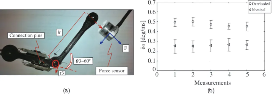
Figure 10.(a) Wing skeleton testbed for torque measurement. (b) (Experimental) measurements of joint speedθ˙3responding to step commands of input currentI, at nominal (I=350 mA) and overloaded (I=550 mA) SMA operation.
From the simulations in figure 9, one can determine the maximum allowed input electrical current that achieves the fastest rotation speed of the elbow joint θ3. This upper
value can be obtained from the limits between overloading and overheating, i.e. above the limits of the finish austenite temperature Af. As long as the input current is smaller than a maximum allowed current, the SMAs will be safe and the angular speed resulting from this input current could be set as a feasible target speed to pursue in the experiment.
Therefore, we have tested the phenomenological model response under different values of input heating current, ranging from 175 mA up to 1A. Figure 9(a) shows the angular rotation profiles (e.g. elbow joint θ3) obtained for
each input current. Figure 9(b) shows increases in the SMA wire temperature corresponding to the results shown in9(a) (cooling temperatures are detailed in the insert). Likewise, figure 9(d) depicts the strain (ε) versus stress (σ) curves corresponding to the results shown in9(b).
Regarding figure9(a), we have used the kinematic model in (1) to relate the strain rate of the SMA wire (ε˙) with the motion of the joint (θ3). Likewise, the strain was computed
using the respective equation described in theappendix. As a first attempt, we applied an input current of 175 mA, this being the value of the nominal input current suggested by the manufacturer of the SMA actuators [13]. Note that under this value, the joint rotates ∼60◦ in 400 ms, a result too slow for the application at hand. As expected, by increasing the input current up to 1A, faster angular motions were achieved (up to 60◦ in 75 ms); however, the SMA finishing austenite temperature (see figure9(b)) was dramatically increased, being
Af = 150◦C, about twice as high as than the upper value defined in the appendix (Af = 78◦C). This issue clearly illustrates an overheating problem. Overheating causes an increase in the cooling time of the SMAs, which makes the actuator slower over a complete wingbeat cycle. It can also cause physical damage to the shape memory effect.
In order to classify the SMA operation modes upon the responses of input heating currents I, four modes of SMA operation have been defined: (1) lower, (2) nominal, (3) overloaded and (4) overheated/overstressed. As observed from the simulations in figure9, both nominal and overloaded modes are feasible targets to pursue with the experiment, e.g., by applying an input current around 550 mA, the joint is able
to rotate 60◦in 100 ms while keeping the maximum limits of temperature and stress below the limits of overheating.
Accordingly, the next tests are carried out to verify whether these limits of SMA operation can be used with the real platform, and how well the phenomenological model predicts the behavior of the SMAs in terms of input current to joint speed. To this purpose, figures10and11present the average results of several elbow joint rotation speeds (θ˙3), the
corresponding output torqueτ3and the required input heating
power (P). Each test has been evaluated in terms of nominal and overloaded SMA operation modes.
Figure10(a) describes the testbed of this experiment. We have used part of the wing skeleton (humerus and radius bones of the wings) including the SMA artificial muscles connected to the elbow joint. Note that in this test, only one direction of rotation is considered (clockwise). The objective is to measure the (i) joint rotation speedθ˙3and (ii) joint output torqueτ3.
The joint speed was measured using the feedback of the
contractedandextendedpins provided by the SMA artificial muscles [13]. These pins activate when the actuator reaches the maximum stroke (contracted) and when lengthen to the neutral position (extended). Figure10(b) shows the root mean square (RMS) speed values obtained for both nominal and overloaded SMA modes. In the nominal mode, the joint speed average was ∼60◦ in 225 ms (0.26 deg ms−1), whereas in the overloaded
mode,∼60◦in 120 ms (0.5 deg ms−1). Comparing both values against the simulation in figure9(a), we have confirmed that both nominal and overloaded modes approximately generate the expected joint rotation speeds (correlation above 80%).
We have also measured the resultant forceF in order to calculate the torqueτ3. The experimental results are shown
in figure 11. A force sensor F/T nano25 manufactured by ATI Industrial Automation8was used. By applying electrical
current signals, ranging from 320 mA to 550 mA, a collection of torque values were plotted corresponding to their respective input heating power (P = I2R), with the initial value of R = 8.5 (Rtypically decreases upon heating as shown in figure7). Table2provides more details about the experiment. In terms of input power, we have observed in figure11
that larger fluctuations were presented when the SMAs were actuating during longer periods of time (i.e. fatigue problems of the SMA wires). This issue is reflected in a decrease of the
0 0.002 0.004 0.006 0.008 0.01 0.012 0.014 0.016 0.018 0
0.5 1 1.5 2 2.5 3
3 [Nm] Measurement Measurement
P
[W]
Figure 11.(Experimental) measurements of output torque (τ3) responding to step commands of input heating power (P). The small plots within the figure correspond to the measured peaks of output torque at nominal (P=1.04 W), and overloaded SMA operation (P=2.57 W).
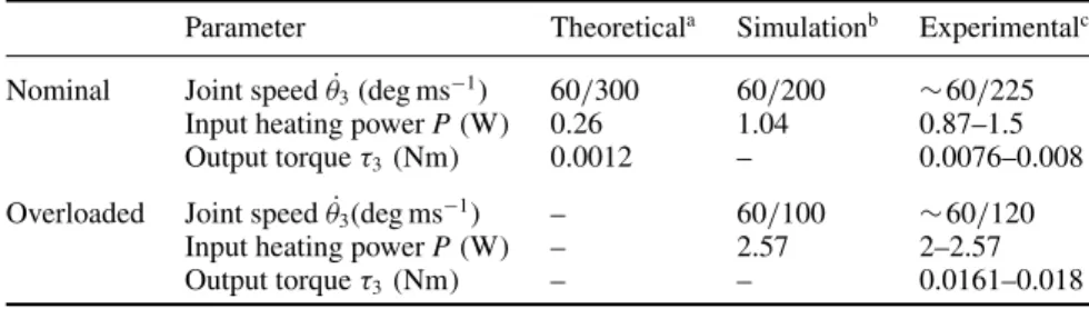
Table 2.SMA muscle performance.
Parameter Theoreticala Simulationb Experimentalc
Nominal Joint speedθ˙3(deg ms−1) 60/300 60/200 ∼60/225 Input heating powerP(W) 0.26 1.04 0.87–1.5 Output torqueτ3(Nm) 0.0012 – 0.0076–0.008
Overloaded Joint speedθ˙3(deg ms−1) – 60/100 ∼60/120 Input heating powerP(W) – 2.57 2–2.57 Output torqueτ3(Nm) – – 0.0161–0.018
aNominal values provided by Migamotor’s model NanoMuscle RS-70-CE 1131 [13]. Overloaded values are not provided.
bSimulation results from figure9. The input heating powerP=1.04 W corresponds to an input current ofI=350 mA (nominal), and P=2.57 W toI=550 mA (overloaded), with nominal electrical resistance ofR=8.5 .
cExperimental results from figure11.
output torque. Fatigue issues will be addressed at the end of the next subsection.
5.2. Morphing wing experiments
Figure 12 shows the experimental setup. Measurements of aerodynamics and inertial forces have been carried out using the Brown University wind-tunnel facility, and a force sensor9
positioned at the center of mass of the robot (below the body). The experiments are focused on the motion of the morphing wings, i.e. wing extension and contraction by means of the elbow motion (see figures 14(a) and (b), respectively). The flapping motion of the wings has not been addressed in this paper. It consists of a basic servo drive that allows the wings to flap within a range of 120◦. The flapping frequency f
(wingbeat) can be increased up to 8 Hz, but at the moment,
9 Nano17 transducer ATI Industrial Automation, 0.318 gram-force of resolution;http://www.ati-ia.com/
it is the morphing frequency that cannot keep up. Therefore, both flapping and morphing wing cycles can be synchronized at f =2.5 Hz due to the limitations in SMA actuation speed.
5.2.1. System identification of morphing wing response. The nonlinear phenomenological model described in theappendix
has been useful to address some important limitations of SMA thermomechanics at least in terms of simulation. However, after the experiments carried out in figures 10 and 11, substantial information about the SMA actuation response was gathered, allowing for its identification.
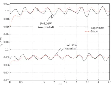
A frequency response analysis has been carried out in order to find the response of a linear system by applying sinusoidal test signals to the input acting as the heating power (Uheating = a +bsin(ωt)) and analyzing the output torque generated by the SMA actuators (τ3) in response to the ac
Bioinspir. Biomim.7(2012) 036006 J Coloradoet al
(a) (b)
(c) (d)
©Brown University ©Brown University
©Brown University ©Brown University
Figure 12.Stills of morphing wing control within the wind tunnel. The wingbeat cycle is composed of two phases: downstroke and upstroke. (a) Beginning of the downstroke. The body of the specimen is lined up in a straight line, elbow joint is∼58◦, (b) end of downstroke, the membrane is cambered and the wings are still extended, elbow joint is∼5◦, (c) middle of downstroke, the wings are extended to increase lift, elbow joint is∼20◦, (d) upstroke, the wings are folded to reduce drag, elbow joint is∼45◦. (a) and (b) illustrate the process to measure aerodynamics loads using the force sensor located at the center of mass of the robot (below the body). (c) and (d) illustrate the process to measure inertial forces at the center of mass produced by both wings (no aerodynamics loads caused by the membrane). Control results are shown in figure14.
with f =2 Hz. As also observed in [19] and [32], the small-signal ac response of the SMA actuators resemble a first-order low-pass filter, whose transfer function is shown as
τ3(s)=K(τs+1)−1=0.016(0.35s+1)−1uheating(s) . (4)
Using (4), the use of a PID controller seems to be suitable for the application at hand.
Figure 13 compares the model in (4) against the experimental response of the SMA actuator to the ac small signal. Note that by applying an input power of ∼1.36 W (I = 400 mA), the output torque τ3 stabilizes around
∼0.008 Nm. This response corresponds to the nominal mode of the SMA actuator. Increasing the input power up to ∼3.06 W (overloaded mode, I = 600 mA), the registered output torque stabilizes around ∼ 0.02 Nm. In both experiments, the anisotropic loading of the 0.1 mm silicone-based wing membrane has been taken into account. Thanks to its highly stretchable property, only a 20% increase in the input heating power was required compared to the values registered in table2.
5.2.2. Morphing wing control. Using the linear model in (4), the PID controller (see figure6) has been tuned using
the Ziegler–Nichols methodology. The PID transfer function is given byU(s) = Kp
1+Kis−1+Kds
, being Kp = 35, Ki=0.006 andKd=0.08.
The response of the morphing controller is shown in figure 14. As previously mentioned, two scenarios were regarded for testing the performance of the control architecture: (i) non-flapping with Vair = 0 m s−1, and
(ii) morphing+flapping atf =2.5 Hz withVair=5 m s−1. The
termVairdenotes the airspeed of the wind tunnel. Performance
is then evaluated in terms of: (i) tracking accuracy, (ii) actuation speed and (iii) SMA fatigue issues.
5.2.3. Tracking accuracy and speed. Figures14(a) and (b) show the experimental results regarding the motion tracking of morphing wing trajectories at a wingbeat cycle of f =
2.5 Hz. In order to analyze the accuracy of the controller, (b) details the time evolution of θ3 during a wingbeat cycle
(t =0.4 s). In this figure, the bio-inspired reference trajectory profile is denoted asθ3,re f, in which the downstroke phase takes 0.22 s (wings extended), and the upstroke 0.18 s (wings folded). Two experiments have been carried out: (i) morphing tracking withVair = 0 and (ii) with Vair = 5 m s−1. After
0 0.5 1 1.5 2 2.5 3 3.5 4 4.5 0.002
0.004 0.006 0.008 0.01 0.012 0.014 0.016 0.018 0.02 0.022
3
[Nm]
t[s]
P=3.06W (overloaded)
P=1.36W (nominal)
Experiment Model
Figure 13.(Experimental) Input power to force small-signal response of the SMA actuators, withUheating=a+bsin(2πf t), f=2 Hz.
0 2 3 6
0.15 0.3 0.45 0.6 0.75
t [s]
I [A]
0 2 4 6
0 20 40 60 80
t [s]
3
[de
g
]
0.1 0.2 0.3 0.4
0 25 50 75
t [s]
3
[de
g
]
0.1 0.2 0.3 0.4
0 0.2 0.4 0.6 0.8
t [s]
P
osition error
(Anti-slack)
~10% of max. current
~ 400ms
(Anti-overload)
(a) (b)
(c) (d)
3 at Vair = 0m/s
3,ref 3,ref
3 at Vair = 0m/s 3 at Vair = 5m/s
error, Vair = 0m/s error,Vair = 5m/s
0 4
Figure 14.(Experimental) morphing wing control response. (a) Tracking of the elbow joint trajectory atf =2.5 Hz,Vair=0 m s−1, i.e. no wind. (b) Close-up to a wingbeat cycle. The two plots describe the control tracking regarding: (i)Vair=0 m s−1(same as (a)), and (ii)
Vair=5 m s−1. (c) Electrical currentIdelivered to the antagonistic SMA actuators, and regulated by the anti-slack and anti-overload mechanisms. (d) Position tracking errors from (b).
position tracking mostly occurred during the upstroke phase. The corresponding errors are shown in figure14(d). During the upstroke, drag forces caused high aerodynamics loads that introduced serious disturbances that are difficult to completely reject.
One might expect that the RM relationship (see algorithm 1 in subsection4.2) provides a feasible indirect measurement of motion at any condition, but at higher speeds, variations
in SMA electrical resistance are presented during the entire wingbeat cycle. This fact is a problem since the RM algorithm evaluates this resistance change only at the end of each wingbeat cycle. This means that the slope correction of the RM function only takes place for the next i+1 stage. As a consequence, accumulative errors are introduced during the estimation of θ3. These errors could be reduced by
Bioinspir. Biomim.7(2012) 036006 J Coloradoet al
0 0.005 0.01 0.015 0.02
3
[Nm]
0 0.005 0.01 0.015
0 0.005 0.01 0.015
0 0.005 0.01
0 1 2 3 4
0.01 0.015 0.02
t [min]
3
[Nm]
0 4 8 12 16
0 0.004 0.008 0.012 0.016
t [min]
3
[Nm]
2.5Hz
1.75Hz
1.35Hz
1.1Hz
1.3Hz 1.23Hz
(a) (b)
(c) 0
5 0.002
0.004 0.006 0.008
0.005 0.01 0.015 0.02
Figure 15.(Experimental) Performance of the SMA actuator for longer periods of actuation. (a) Nominal operation at 1.3(Hz). (b) Overloaded operation at 2.5(Hz). (c) Output torque peaks extracted from overloaded response in (b).
Table 3.Performance data of SMA actuation for longer periods of time.
Output Actuation % Performance Time torque speed reductiona
Nominal initial 0.007(Nm) 1.3(Hz) – 16(min) 0.0068(Nm) 1.23(Hz) 5%
initial 0.018(Nm) 2.5(Hz) –
Overloaded 1.5(min) 0.015(Nm) 1.75(Hz) 30% 3(min) 0.011(Nm) 1.35(Hz) 46% 5(min) 0.008(Nm) 1.1(Hz) 56%
a% of reduction in the actuation speed.
actuation speed, the implemented control architecture allowed the system to operate successfully atf =2.5 Hz. As previously explained in subsection4.1, the adapted slack and anti-overload mechanisms contributed to speed-up SMA actuation.
5.2.4. Fatigue issues. The last performance criterion to evaluate relates to the fatigue phenomenon. Most of the previous experiments were carried out for short periods of time. However, contracting and extending the wings at 2.5 Hz requires peaks of input power∼3 W, which could cause the SMA to fatigue over time.
Fatigue issues have been observed, causing the output torque of the SMA actuators to decrease over time. As a consequence, SMA performance in terms of actuation speed also decreases quickly as a function of time. Figures 15(a) and (b) show the measured output torque curve produced by the SMA actuators at both nominal and overloaded operation modes. The optimal performance (f = 2–2.5(Hz)) can be maintained up to 1.5 min, without compromising the actuation speed (at minute 1.5, the reduction in output torque is about 4.5%). Figure 15(c) shows the measured peaks of torque produced by the elbow joint during rotation. Each peak corresponds to the four critical points highlighted in 15(b). Table3summarizes the data.
After 5 min of continuous overloaded operation, the wingbeat frequency has decreased from f =2.5 Hz to 1.1 Hz
(stabilizing around 1 Hz). This corresponds to ∼56% of performance decrease in terms of actuation speed. On the other hand,under nominal mode (see figure 15(a)), results have shown that the SMA actuators tend to stabilize around 1–1.2 Hz. These results confirm that constant output torque in a Migamotor actuator can be only maintained under nominal operation at SMA contraction speeds of 300 ms [13]. Once overloaded, the critical fatigue point is presented about 1.5 min of continuous operation; however, it has been observed that once the SMA actuator is completely cooled, it is able to raise the maximum operating frequency of 2.5 Hz during another 1.5 min. Table 3 details the performance data. In particular, methods for removing or reducing fatigue phenomena must be analyzed. One of these methods could be based on investigations related to high-frequency responses of SMAs and the possibility of using high-bandwidth control systems as an approach to eliminate limit cycles. As demonstrated by [19], high-bandwidth force control could be a solution.
5.3. Aerodynamics experiments
Initial aerodynamics analyses were previously introduced in section3.2. In the tests depicted in figure5, we experimentally measured the lift and drag coefficients of the fabricated wings’ membrane as a function of the angle of attack of the airfoil. The wings were fixed to the robot at mid-downstroke, whereas the angle of attack was increased up to 25◦. In this section, we have tested the aerodynamics behavior of the entire robot, performing both flapping and morphing wing motions within the wind-tunnel facility. The experiments carried out in figure16are focused on analyzing the changes in lift and drag that are induced by the morphing wing.
0 5 10 15 0
0.5 1 1.5
Angle of attack [deg]
CL and CD
0 5 10 15
4 6 8 10 12
Angle of attack [deg]
L/D
0 5 10 15 20
4.995 5 5.005 5.01
Measurements V air
[m/s]
0 5 10 15
0 0.2 0.4 0.6 0.8 1 1.2
Angle of attack [deg]
L and D Forces [N]
CL non-morphing
CL morphing
CD morphing
CD non-morphing
(a) (b)
(c) (d)
L
D
Figure 16.(Experimental) Aerodynamics measurements. (a) Comparison between lift and drag coefficients (CL,CD) with and without the motion of the morphing wings (Vair=5 m s−1, wingbeat frequency off=2.5 Hz). (b) Lift-to-drag ratio (L/D) as a function of the angle of attack (Vair=5 m s−1, f=2.5 Hz ). (c) Wind tunnel airspeed measurements (Vair). (d) Lift (L) and drag (D) forces corresponding to (a) (with morphing).
Table 4.Lift and drag measurements for an angle of attack of 9◦and
Vair=5 m s−1.
Lift force Drag force
L[N] D[N] CL CD
Non-morphing 0.67 0.17 1.03 0.26 Flapping+morphing 0.97 0.099 1.5 0.152 (f =2.5 Hz)
the flapping trajectory is a simple sinusoidal signal with an amplitude of±60◦with f =2.5 Hz.
In terms of lift production, note how the lift coefficient is increased about 46% when the wings are flapping and expanding during the downstroke. We have observed that the major contribution in increasing lift forces was due to the flapping motion, accounting for about 28%. The morphing-motion contribution accounted for about 18% thanks to wing area maximization during the downstroke. On the other hand, the drag coefficient was reduced about 40% by means of folding the robot’s wings. The angle of attack corresponding to these measurements in 10◦.
Another important measurement corresponds to the lift-to-drag ratio L/D (see figure 16(b)). It has allowed us to determine which is the most effective angle of attack that ensures a higher lift force and lower drag. This angle corresponds to 9◦ (straight flight). At this angle, the corresponding lift and drag forces are shown in figure16(d), being the lift force 0.97 N, about 26% more than the bat’s weight force of 0.77 N. Table4details these results.
6. Conclusions
Taking inspiration from nature, and in particular the morphology and flight kinematics of bats, we have proposed a biomechanical and control system design that takes advantage of the morphing-wing capability of the bat flight apparatus. Although a conventional servo system is used for the primary flapping mechanism, the proposed control enables the bat robot to perform bio-inspired morphing-wing motions using shape memory alloys (SMAs) used as artificial muscles for wing retraction and extension. Experiments were carried out to analyze how to properly speed-up the operation of the SMAs to ensure their feasible use for the application at hand.
In terms of control, the adopted slack and anti-overload mechanisms prove to effectively work in a position control scheme, by servoing SMA electrical resistance changes to accurately estimate the morphing motion of the wings. Thanks to the implemented RM relationship, both mechanisms were analyzed and experimentally adjusted for regulating the amount of input heating power to be delivered to the SMA artificial muscles. The fact that our robot does not make use of any motion sensor to provide the angular position feedback, and yet achieves satisfactory tracking errors (even under the presence of high aerodynamics loads), represents a validation of this control approach.
Bioinspir. Biomim.7(2012) 036006 J Coloradoet al
Table A1.Nonlinear SMA phenomenological model.
Variable Model Parameters Description Value (unit)
Temperature Heating: ms,R,I Mass, resistance, current 1.14×10⁻⁴(kg), 8.5( ) (T) mscpT˙=I2R−hcAc(T−To) Ac Wire circumferential area 1.76×10⁻⁸
m2
Cooling: hc Heat convection coefficient 150
Jm−2◦C−1s−1
mscpT˙= −hcAc(T−To) Cp Specific heat 0.2
Kcal kg−1◦C−1
Stress (σ) Heating: Phase transformation factor −1.12(GPa)
˙
σ = θs− (Af−As)−1
1− (Af−As)−1Cm
˙
T θs Thermal expansion factor 0.55
MPa◦C−1
Cooling: Cm,Ca Effect of stress on temperature 10.3
MPa◦C−1
˙
σ = θs− (Ms−Mf)−1
1− (Ms−Mf)−1Ca
˙
T As,Af,Ms,Mf Temp.: austenite, martensite 68,78,52,42(◦C)
Strain(ε) Heating:
˙
ε= σ˙−θsT˙− ξ˙
EA EA Austenite Young mod. 75(GPa)
Cooling: EM Martensite Young mod. 28(GPa)
˙
ε= σ˙−θsT˙− ξ˙
EM
FM (ξ) Heating: ξm, ξa FM constants 1, 0 (dimensionless)
ξ= ξm
2 [cos(aA(T−As)+bAσ )+1] aA Austenita amplitude factor 0.31
◦
C−1
Cooling: aM Martensite amplitude factor 0.31
◦
C−1
ξ= 1−ξa
2
cosaM
T−Mf
+bMσ
+1+ξa
2
bA,bM Stress coeff. −0.03
◦
C−1
Actually, the wings of biological bats have tiny hairs that sense airflow conditions, and there is some evidence that this sensing apparatus in bats contributes to their flight efficiency [33]. Besides the elbow contraction, their three DoF wrist joint also contributes to folding the digits toward the body. As a consequence, bats can reduce their wingspan about 70% during the upstroke [16]. In this work, we have attempted to mimic part of that complexity; however, our robot is able to reduce its wingspan about 23% during the upstroke (from 0.53 m to∼0.41 m). This mechanical limitation is due to the fact that the wrist joints are under-actuated, i.e. rotate as a function of the elbow motion via steel tendons. Therefore, the wrist joint only contributes about 5% during wing contraction. Significant drag reduction still remains a challenge.
Experiments regarding fatigue issues have allowed us to verify the limits of this actuation technology. In particular, further investigations will be devoted to quantifying the lifetime of SMAs when subjected to higher stresses and larger heating currents. Methods for removing or reducing fatigue phenomenon must be analyzed. One of these methods could be based on investigations related to high-frequency responses of SMAs and the possibility of using high-bandwidth control systems as a possible approach to eliminate limit cycles.
The developments presented in this paper are a key step towards achieving the first bat-like robot capable of sustained autonomous flight. The possibility of controlling the shape of the wings has great potential to improve the maneuverability of current micro aerial vehicles. Current research is devoted to the overall flight control, implementing how the bat robot can maneuver by means of changing its wing shape, using the morphing wing control mechanism presented herein.
Acknowledgments
This work is funded by the ROBOCITY 2030-II, sponsored by the Community of Madrid (S-0505/DPI/000235) and by the
US Air Force Office of Scientific Research. The assistance of Rye Waldman and Joe Bahlman in the wind tunnel measurements is particularly appreciated.
Appendix. SMA phenomenological model
Table A1 shows the SMA phenomenological model (see
[29,30] for further details).
References
[1] Iriarte-Diaz J, Riskin D K, Willis D J, Breuer K S
and Swartz S M 2011 Whole-body kinematics of a fruit bat reveal the influence of wing inertia on body accelerations
J. Exp. Biol.2141546–53
[2] Swartz S M, Groves M D, Kim H D and Walsh W R 1996 Mechanical properties of bat wing membrane skinJ. Zool.
239357–78
[3] Swartz S M, Bishop K L and Ismael-Aguirre M-F 2005 Dynamic complexity of wing form in bats: implications for flight performanceFunctional and Evolutionary Ecology of Bats(Oxford: Oxford University Press) pp 110–30 [4] Riskin D K, Willis D J, Iriarte-Diaz J, Hedrick T L,
Kostandov M, Chen J, Laidlaw D H, Breuer K S and Swartz S M 2008 Quantifying the complexity of bat wing kinematicsJ. Theor. Biol.254604–15
[5] Lindhe-Norberg U M, Brooke A P and Trewhella W J 2000 Soaring and non-soaring bats of the family Pteropodidae (flying foxes, Pteropus spp.): wing morphology and flight performanceJ. Exp. Biol.203651–64
[6] Pons J L 2007Emerging Actuator Technologies: A
Micromechatronic Approach(New York: Wiley) pp 1–301 [7] Ouyang P, Clement R, Zhang W J and Yang G S Micro motion
devices technology: the state of arts reviewJ. Adv. Manuf. Technol.38463–78
[8] Bundhoo V, Haslam E, Birch B and Park E J 2008 A shape memory alloy-based tendon-driven actuation system for biomimetic artificial fingers, part I: design and evaluation
[9] Rossi C, Coral W, Colorado J and Barrientos A 2011 A motor-less and gear-less bio-mimetic robotic fish design
ICRA 2011: Proc. IEEE Int. Conf. on Robotics and Automation (Shanghai, 9–13 May 2011)pp 3646–51 [10] Rossi C, Colorado J, Coral W and Barrientos A 2011 Bending
continuous structures with SMAs: a novel robotic fish designBioinspir. Biomim.6045005
[11] Bunget G 2010 BATMAV—a bio-inspired micro-aerial vehicle for flapping flightPhD ThesisNorth Carolina State University (available athttps://sites.google.com/site/ /gheorghebunget/research/batmav)
[12] Yang S and Seelecke S 2009 FE analysis of SMA-based bio-inspired boneÐjoint systemSmart Mater. Struct.
18104020
[13] Migamotors Company,www.migamotors.com
[14] Tian X, Iriarte-Diaz J, Middleton K, Galvao R, Israeli E, Roemer A, Sullivan A, Song A, Swartz S and Breuer K 2006 Direct measurements of the kinematics and dynamics of bat flightBioinspir. Biomim.1S10–8 [15] Watts P, Mitchell E J and Swartz S M 2001 A computational
model for estimating the mechanics of horizontal flapping flight in bats: model description and validationJ. Exp. Biol. 2042873–98
[16] Riskin D K, Iriarte-Diaz J, Middleton K M, Breuer K S and Swartz S M 2010 The effect of body size on the wing movements of pteropodid bats, with insights into thrust and lift productionJ. Exp. Biol.2134110–22 [17] Alexander D A 2002Natures Flyers: Birds, Insects and the
Biomechanics of Flight(Baltimore, MD: Johns Hopkins University Press)
[18] Hedenstrm A, Johansson L C, Wolf M, von Busse R, Winter Y and Spedding G R 2007 Bat flight generates complex aerodynamic tracksScience316894–7
[19] Yee T 2008 Fast, accurate force and position control of shape memory alloy actuatorsPhD ThesisAustralian National University
[20] Teh Y H and Featherstone R 2008 An architecture for fast and accurate control of shape memory alloy actuatorsInt. J. Robot. Res.27595–611
[21] Kohl M 2004Shape Memory Microactuators(Berlin: Springer)
[22] Grant D and Hayward V 1997 Variable structure control of shape memory alloy actuatorsIEEE Syst. Control Mag.
980–8
[23] Grant D 1999 Accurate and rapid control of shape memory alloy actuatorsPhD ThesisMcGill University
[24] Zhong Z W and Yeong C K 2006 Development of a gripper using SMA wireSensors ActuatorsA126375–38 [25] Ma N, Song G and Lee H-J 2004 Position control of shape
memory alloy actuators with internal electrical resistance feedback using neural networksSmart Mater. Struct.
13777–83
[26] Tai N T and Ahn K K 2011 Adaptive proportional–integral– derivative tuning sliding mode control for a shape memory alloy actuatorSmart Mater. Struct.20055010
[27] Tanaka K 1986 A thermomechanical sketch of shape memory effect: one-dimensional tensile behaviorRes. Mech. 18251–63
[28] Brinson L C 1993 One-dimensional constitutive behavior of shape memory alloys: thermomechanical derivation with non-constant material functions and redefined martensite internal variableJ. Intell. Mater. Syst. Struct.
4229–42
[29] Elahinia M H 2004 Effect of system dynamics on shape memory alloy behavior and controlPhD ThesisVirginia Polytechnic Institute and State University
[30] Elahinia M H and Ahmadian M 2005 An enhanced SMA phenomenological model: I. The shortcomings of the existing modelsSmart Mater. Struct.141297–308 [31] Esfahani E and Elahinia M 2007 Stable walking pattern for an
SMA-actuated bipedIEEE/ASME Trans. Mechatron.
12534–41
[32] Kuribayashi K 1991 Improvement of the response of an SMA actuator using a temperature sensorInt. J. Robot. Res.
1013–20

![Figure 8. Joint trajectory of the elbow joint during a wingbeat cycle ( f = 1.25 Hz). The profile has been extracted from biological experiments conducted on the Pteropus poliocephalus specimen (steady flight), reported in [15].](https://thumb-us.123doks.com/thumbv2/123dok_es/6766489.830269/8.892.458.824.496.776/trajectory-extracted-biological-experiments-conducted-pteropus-poliocephalus-reported.webp)