1
Preparation and Characterization of Catalytic Membrane
Reactors
Preparación y Caracterización de Reactores Catalíticos de
Membrana
Verónica Pinos1, 2, 3, Francesc Medina1, Anton Dafinov1.
1
Chemical Engineering Department, Rovira i Virgili University, Av. Països Catalans 26, Tarragona 43007, Spain
2 Departamento de Recursos Hídricos y Ciencias Ambientales, Universidad de Cuenca, Av. 12 de
abril, Cuenca, Ecuador
3 Facultad de Ciencias Químicas, Universidad de Cuenca, Av. 12 de abril, Cuenca, Ecuador
veronica.pinos@ucuenca.edu.ec; francesc.medina@urv.cat; anton.dafinov@urv.cat
Recibido: 21-11-2016. Aceptado después de revisión: 11-1-2017
Resumen: Los Reactores Catalíticos de Membrana, RCM, nos dan la posibilidad de optimizar diversos procesos industriales. La versatilidad que tienen los RCM reside en que pueden ejecutar varias funciones, como por ejemplo, filtración, dosificación y catálisis. Este trabajo propone cuatro formas de preparación de RCM en modo contacto interfacial, para ser evaluados en remediación ambiental. Para la preparación de RCM, se emplearon membranas comerciales de fibra hueca de corindón. Como principal fase activa se usó paladio, el cual fue depositado por diferentes métodos tales como impregnación, sputtering (pulverización catódica) y microemulsión; también se usaron nanopartículas de paladio-cobre obtenido por el método del poliol. Los reactores obtenidos fueron probados en la generación in situ de peróxido de hidrógeno y la oxidación de fenol en medio acuoso a presión atmosférica y a temperatura ambiente o a 60°C. Los mejores resultados se obtuvieron con el RCM que contenía paladio por impregnación. Los otros RCM presentaron en todos las pruebas una rápida desactivación.
Palabras claves: Reactores Catalíticos de Membrana, RCM, Nanopartículas de Paladio, Tratamiento de agua, catálisis
Abstract: Catalytic Membrane Reactors, CMR, are well known because of their versatility to develop various industrial processes. This versatility lies in CMR’s ability to run many functions in a single device. These functions can be filtration, dosage and catalysis. This work proposes four ways to prepare CMRs in interface mode to be tested in environmental remediation. For the preparation of Catalytic Membrane Reactors, commercial Hollow Fiber Membranes made of corundum were used. Palladium, as the main active phase, was synthesized by different methods such as impregnation, sputtering and microemulsion. Moreover, copper palladium alloy nanoparticles were obtained by the polyol route. The reactors obtained were tested in aqueous medium, at atmospheric pressure and low reaction temperatures (< 60°C) in the following reactions: in situ generation of hydrogen peroxide and phenol oxidation. The best results were achieved with the CMR with palladium prepared by impregnation. The others CMRs showed fast deactivation in all tests.
2
1. Introduction
A membrane reactor is a device that combines a membrane separation or distribution process with a chemical reaction in a single unit. Membrane Reactors are capable of promoting a reaction process by: (1) selectively removing at least one of the products from the reaction zone through the membrane, making the equilibrium reaction shift to the product side, and (2) supplying only a particular reactant to the reaction zone, thus giving an optimum concentration ratio of the two reactant streams. As a result, the yield can be increased (even beyond the equilibrium value for equilibrium reactions) and/or the selectivity can be improved by suppressing other undesired side reactions or the secondary reaction of products [1]. The simultaneous separation show advantages related to the process and the reaction: (1) it reduces the flow rate of the reactant stream, whilst increasing the residence time; (2) it increases the reactant concentration and hence the forward reaction rate; and, (3) it reduces product concentration, reducing the reverse reaction rate [2]. An important advantage is that in the reactor the membrane is able to retain homogeneous catalysts. Thus, it allows continuous operation without needing to separate and recycle catalysts [3]. Membrane Reactors (MR) have three generic approaches: extractors, distributors and contactors; Membrane Reactors as an extractor selectively remove certain products from the reaction zone [3], [4]. The MR as a distributor enhances the selectivity through optimizing of the reactant dose [3]. That is, by selectively distributing one of the reactants [5]. Both a perm-selective and a nonperm-selective membrane can be used to distribute one of the reactants [4]. The Membrane Reactor as a contactor intensifies the contact between the reactants and the catalyst [3], [6], [7].
An important type of the Membrane Reactor is the Catalytic Membrane Reactor (CMR). A CMR is a device which perm selective membrane is one of the catalytic type or has a catalyst deposited in or on it [8], [9]. In the CMR, the membrane provides simultaneously the separation and reaction functions. To accomplish this purpose, it could use either an intrinsically catalytic membrane where the same material acts as a catalyst and as a membrane (e.g., zeolite or metallic membrane), or a membrane that acts as a catalytic medium through activation, by introducing catalytic phases by either impregnation or ion exchange. In this case, a membrane only facilitates mass transfer [10], [11]. For instance, palladium membrane is used as hydrogen permselective CMR [9]. Targeted benefits of CMRs are seen at three different levels: a) process level, eliminating process units and phase changes among them. The integration of a separation function into the reactor allows reduction of the amount of process units, b) reactor level, optimizing the contact between the phases and the dosing strategy, and c) catalyst level, influencing catalysis through the chemical nature of the membrane [12].
3
reactors [11]. In this concept, an unselective porous catalytic membrane is applied in the dead-end mode, forcing the reactants to flow through the membrane. The function of the reaction is to provide a reaction space with short controlled residence time and high catalytic activity. High pressures are not required even for low solubility, e.g. the gas is supplied directly where it is consumed. CMRs in flow-through mode are mostly applied to gas-phase reactions, with a few exemptions of liquid phase or multi-phase reactions [6]. The unselective interfacial contactor is the concept most closely related to the flow-through Catalytic Membrane Reactor. Both use unselective catalytic membranes and in both concepts the membrane provides the reaction space. Consequently, the applications are somewhat similar. The difference is that, in the interfacial contactor mode, the reactants are fed from different sides of the membrane, whereas in forced flow-through mode the premixed reactants are supplied from the same side in dead-end mode [6].
Due to the modular character of the reactors, the process is easily scalable and opens the possibility for large-scale applications. CMRs have been used successfully in hydrogenation and oxidation processes [10], [14]–[16]. For instance, studies have demonstrated that CMRs can be used to eliminate different contaminants such as phenol through advanced oxidation processes [16]–[18]. Furthermore, CMRs have used for hydrogenation of phenol and ibuprofen [16]; in-situ generation of hydrogen peroxide and chromium (VI) reduction in water solution [19], [20]. The CMRs are promising devices that can successfully be used in different processes at industrial processes at mild conditions. Due to the advantages of CMRs in interface mode, this work is focused on the development of Catalytic Membrane Reactors to be tested in industrial applications, centering on environmental remediation.
2.Materials and Methods
2.1 Corundum Hollow Fibers Membranes
Corundum Hollow Fiber Membranes of 200 nm of porous size for ultra and nano filtration manufactured by CeparationTM were used as the starting material for the preparation of the Catalytic Membrane Reactors. Each hollow fiber is made of alpha alumina (α-Al2O3). The Hollow Fiber
Membranes present chemical resistances to different chemicals in a wide range of pH (1-14). Additionally, these fibers have high thermal stability and, as a result, they may be used at temperatures up to 1000°C. The porosity of the membranes varied from 10 % to 15 %. The used membranes have an inner diameter of 2 mm and an outer diameter of 3 mm with a total length of 300 mm. Each Catalytic Membrane Reactor was prepared by using a 150 mm fragment of the membrane (see figure 1).
2.2 Methods used to prepare the Catalytic Membrane Reactors
The Catalytic Membrane Reactors used in this study are obtained after the active phases are supported within the Corundum Hollow Fiber Membrane. All CMRs contain three active phases: cerium oxide, iron oxide and palladium or palladium-copper alloy.
2.2.1 Cerium and iron oxide on CMR obtained by impregnation method.
The procedure of Pd deposition onto the membrane has been thoroughly described in other articles from the research group [18], [19]. CMRs were prepared using the impregnation technique starting with water soluble precursor salts: Ce(NO3)3.6H2O (purity grade > 99.9 %, Aldrich) and FeCl3.6H2O
4
450°C for 6 h, in oxygen rich environment. The amounts of oxides deposited were calculated by the weight difference between the originals and the modified membranes. Once, the CMRs containing cerium oxide and iron oxide were obtained, subsequent incorporation of the Pd was performed. The palladium or palladium alloys were introduced following different methods:
a. By impregnation of the soluble Pd precursor.
b. By sputtering using a specially prepared device.
c. Synthesis of Pd or Pd-Cu nanoparticles in microemulsions following different methods. Once the active phases were prepared the deposition onto the CMRs was done by filtration.
2.2.2. Palladium on CMR obtained by impregnation method.
The procedure of Pd deposition onto the membrane has been thoroughly described in our previous works [18]–[20]. The precursor salt solution of palladium was PdCl2 (Johnson Matthey) with 59.83 %
of the noble metal. First, a known amount of the precursor salt was added into Milli-Q water, whilst stirred. Then, concentrated hydrochloric acid (purity grade of 37 %, sigma Aldrich) was added in a drop wise manner into the solution until the salt was completely dissolved. Finally, the concentration was adjusted with Milli-Q water in order to achieve approximately 1 % of weight of Pd per weight of the membrane. The palladium precursor solution was impregnated into the membrane. Once the impregnation was complete, the Catalytic Membrane Reactors were dried in a special vessel under vacuum for 30 min. In this step, the CMR was rotated along the horizontal axis in order to avoid preferential deposition of the salts onto the ceramic support. Furthermore, the CMR was dried at 120°C for 5 h and finally calcined at 450°C overnight. The palladium loaded onto the CMR was further activated by reduction under 20 sccm/min flowing hydrogen at 350°C for 3 h. The amount of palladium deposited was calculated by the weight difference between the original and the modified membrane.
2.2.3. Palladium on CMR obtained by sputtering method
The incorporation of the catalytic phases onto the membranes by impregnation is a well-known technique that achieves homogeneously distributed active phases within the supports. However, in the case of the proposed CMRs, the chemical reactions occur at the external surface of the membranes. In order to assure more efficient use of the precious metal, Pd deposition onto the membranes was achieved using a conventional sputtering chamber.
5
Thereafter, the amount of palladium deposited onto the membrane was estimated taking into account the effective membrane area exposed to the palladium beam as well as the rotationvelocity. Finally, the Catalytic Membrane Reactor was dried at 120°C for 2 h, calcined at 600°C overnight, and reduced at 350°C under 20 sccm/min H2 for 2 hours.
2.2.4. Palladium on CMR obtained by microemulsion method
Another method was chosen for the selective Pd deposition into the reaction zones of the membranes. It consists of two steps. First, Pd nanoparticles are synthesized in microemulsions. Secondly, after the proper washing procedure the suspension containing the Pd nanoparticles was filtered with the membrane (from the outer to the inner part of the membrane) assuring the deposition of the active phase on the desired membrane surface. The microemulsion containing the Pd precursor was synthesized following the procedure described by Wang et al. [21]. According to the authors, the obtained palladium nanoparticles are 8 nm in size. That is, the nanoparticles were obtained by mixing two microemulsions of water in oil. Both microemulsions contained 17.78 % w/w of hexadecyltrimethylammonium bromide (CTAB) as a surfactant (purity ≧ 96 %, Fluka Analytical), 22.22 % w/w of n-butanol as a co-surfactant (purity 99.8%, Sigma Aldrich), 40 % w/w of iso-octane (from Pareac) and 20 % w/w of an aqueous solution of the metal precursor or reducing agent. The palladium precursor aqueous solution was 0.01 M Pd(NH3)4Cl2. The second emulsion containing the
reducing agent was prepared using 0.5 M of hydrazine solution. The solution of 0.01 M of the Pd(NH3)4Cl2 was prepared by dissolving PdCl2 (Johnson Matthey, 59.83 % metal content) in 0.5 N
hydrochloric acid. The solution was adjusted to pH 9 using ammonium hydroxide (Sigma Aldrich). The solution of 0.5 M H4N2 was obtained by dissolving H4N2.OH (hydrazine monohydrate with
approximately 64 % of hydrazine, Sigma Aldrich) in Milli-Q water. The two microemulsions were obtained under vigorous stirring at ambient temperature after mixing the corresponding parts described above. In order to obtain the palladium nanoparticles, both microemulsions were mixed and rapidly stirred at 450 rpm. In approximately 20 minutes the palladium ions were reduced by the hydrazine and the Pd particles were formed. The formation of the Pd particles was change was easily detected due to the color change. To eliminate the excess surfactant, the solution was washed with ethanol until no surfactant was observed. A simple test was used to verify the presence of surfactant in the spent washing solution. A drop of the spent solvent was placed on dark paper and after the ethanol was evaporated a white stain remains indicating the presence of residual surfactant. In order to separate the palladium nanoparticles from the liquid after the alcohol addition, the mixture was centrifuged with a BR4i centrifuge. The first separation was performed at 9000 rpm for 40 min; the next was set at 8000 rpm for 20 min. In all cases, ¾ parts of the liquid was withdrawn and tested for the presence of the surfactant. If the test confirmed that are surfactant was still remaining in the solution, more ethanol was added and the steps described above were repeated. Finally, the washed palladium nanoparticles were obtained in the form of a suspension in ethanol. Their deposition onto the external surface of the chosen membrane was performed by a simple filtration procedure from the outside to the inside of the membrane.
6
appropriate digestion with HCl and HNO3 acids. Once the palladium was placed in the CMR, it was
dried in a special vessel under the vacuum for 30 min. Furthermore, the CMRs were dried at 120°C for 2 h and finally calcined at 550°C overnight. The CMRs containing palladium were reduced under hydrogen flow adjusted to 20 sccm/min using the Allicat Scientific mass flow controller at 350°C for 3 h.
2.2.5 Palladium copper alloy nanoparticles on CMR obtained by polyol synthesis route
The incorporation of copper into the crystal lattice of Pd does not decrease the capacity of the resulting alloy for hydrogen activation in respect to the pure Pd, but at the same time, it stabilizes the crystal structure, such that the formation of β-palladium (PdHx, x > 0.58) is prevented. In order to check this
assumption, Pd-Cu nanoparticles were synthetized in different ratios. The procedure reported by Meshesha et al. [22], with some modification, was followed to synthesize the Pd-Cu alloy nanoparticles. The Pd(C5H7O2)2 (Heraeus with 34.97 % of palladium) and Cu(NO3)2.3H2O (Sigma
Aldrich of 98 % – 103 %) were used as precursors salts for palladium and copper, respectively. The palladium salt was dissolved in ethylene glycol (99 % purity, Sigma Aldrich). The amount of palladium salt used was adjusted in order to obtain a 0.05 M concentration. In another flask, a 0.05 M solution of copper salt in ethylene glycol was prepared. To each of those solutions 1-hexadecylamine (HDA) (Aldrich, purity 90 %) was added in molar ratio of 3:1 with respect to the metal content. In order to adjust the Pd:Cu molar ratio to 4:1 the corresponding volumes from both solutions were taken and mixed. The mixture was stirred for one hour in an ice bath in order to avoid an early metal reduction. The homogeneous mixture was then heated at 140ºC in a reflux for 12 h. During the temperature increase a color variation of the liquid was observed; the initial green gradually transformed to blue, then red to black in the end. The changes indicate the formation of Pd-Cu alloy particles obtained by the reducing effect of ethylene glycol. The surfactant molecules of HAD act mainly as stabilizers in the particles formation. Finally, the nanoparticles were extracted with toluene. The nanoparticles were deposited into the CMR containing the cerium and iron oxide using the same procedure as described before for palladium nanoparticles obtained by the microemulsion method.
2.3 Characterization of Catalytic Membrane Reactors (CMRs)
2.3.1 Transmission electron microscopy (TEM)
Transmission electron microscopy was employed to examine the Pd nanoparticles in the Catalytic Membrane Reactor. The equipment used was the transmission electron microscopy, TEM, JEOL model 1011 from Servei de Recursos Científics i Tècnics of URV. A piece of the CMR was crushed and the powder was dispersed in ethanol for the samples obtained by impregnation, sputtering and microemulsion. The nanoparticles obtained by polyol route without having support were analyzed directly. Then, a drop of the sample in suspension was placed into a copper grid. The grid was dried and placed in the TEM to be observed. The sizes of the observed Pd particles were determined using the ITEM software by Olympus.
2.3.2 X-ray diffraction (XRD)
7
cm away from the sample. A frame (2D XRD patterns) covering 24 – 56o 2θ was collected. The exposure time was 900 s per frame and it was chi-integrated to generate the conventional 2θ vs. intensity diffractogram. Image scale: small lines separation corresponds to ≈ 100 μm. The average area analyzed was represented by an ellipsoid centered in the cross with a constant short axis of 0.5 mm (N-S direction) and a variable long axis (from 1.5 to 0.6 mm in the W-E direction). The analysis of the XRD diffractogram was performed by the ICDD database (release 2007) using Diffracplus Evaluation software (Bruker 2007).
2.4 Test of Catalytic Membrane Reactors (CMRs)
The reactors obtained were tested in the following reactions: In situ generation of hydrogen peroxide and phenol oxidation.
2.4.1 In situ generation of hydrogen peroxide
The activities of the CMRs were tested in the in-situ generation of H2O2 using the method described
in Osegueda et al [19]. All CMRs were tested in semi-batch mode. Each CMR was introduced in a vessel containing 100 mL Milli-Q water. Hydrogen flow of 6 sccm/min was supplied to one end of the CMR whilst the other end was kept closed. In this way, the hydrogen was passed across the membrane wall reaching the external surface. Air was bubbled into the water as an oxygen source in the reactor vessel. Thus, the Catalytic Membrane Reactor put in contact the hydrogen, oxygen and the solid catalyst. High performance liquid chromatography, HPLC Shimadzu, equipped with LC 20AB system and with a diode array detector SPD-M10Avp, was used to measure the concentrations of hydrogen peroxide. Hydrogen peroxide was analyzed at a wavelength of 193 nm after direct injection of the sample without a column. The mobile phase was Milli-Q water.
2.4.2 Phenol oxidation
CMRs were subsequently tested in advanced oxidation processes to mineralize phenol using the method described in previous works [16], [18]. The Catalytic Membrane Reactors were tested in 100 ppm of phenol water solution in semi-batch mode. The hydrogen flow was adjusted using a mass flow controller and supplied to one end of the reactor whilst the other end was kept closed. The hydrogen supply was 6 sccm/min. The hydrogen crosses the membrane wall reaching the external surface. The CMR was submerged into a glass reactor containing 100 mL of the phenol water solution. All the tests were performed at 60 °C for 7 h at atmospheric pressure. The concentrations of phenol during the tests were measured every hour using the described HPLC. A column C-18 (Omnisphere, Varian), ID. 4.6 mm, length 250 mm. The analysis of the phenol was made at a wavelength 254 nm. The mobile phase of 1 mL/min was a mixture of 60 % water at pH 3 adjusted with acetic acid and 40 % of acetonitrile (Aldrich). The total organic carbon was measured with TOC-L Shimadzu CSN equipment. Only the initial and the final samples were assessed.
3. Results and Discussion
3.1 Catalytic Membrane Reactors (CMR)
8
The notation used to name the CMR has three parts: Beginning, active phase(s) included in the CMR: Pd (palladium), Fe (iron oxide) and Ce (cerium oxide). M means corundum Hollow Fiber Membrane without active phase(s). Middle, pore size of the Hollow Fiber Membrane: 200 (200 nm). End, first letter of the method used to obtain palladium or copper palladium nanoparticles: i (impregnation), s (sputtering), m (microemulsion), and p (polyol route).
Tabla 1. Catalytic Membrane Reactors (CMR)
CMR Method Pores size (nm) % Fe2O3 % CeO2 % Pd
FeCePd-200-i Impregnation 200 1.5[19] 1.3[19] 1.2[19]
FeCePd-200-s Sputtering 200 1.8 1.8 0.02
FeCePd-200-m Microemulsion 200 2.15 2.15 0.1
FeCePdCu-200-p Polyol route 200 2.15 2.15 0.5 (20 % Cu 80 % Pd)
FeCe Impregnation 200 1.5 1.5 0
M - 200 0 0 0
Figura 1.Picture of different CMRs: Top, hollow fiber used for the blank tests; Middle, CMR with iron and cerium
oxide; Below, CMR with three phases, iron and cerium oxide and palladium.
In figure 1 a picture of the Catalytic Membrane Reactors made with a commercial Hollow Fiber Membrane are shown.
9
3.2 Characterization of Catalytic Membrane Reactors (CMR)
3.2.1 TEM
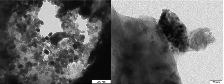
Figure 2 shows a TEM picture of the corundum Hollow Fiber Membrane without catalytic phases. Corundum can be seen as unique constitutive material of the membranes as was expected.
Figure 2.Picture of Corundum Hollow Fiber Membrane.
Figures 4a, c, e, g show the palladium nanoparticles obtained by different methods. Fig. 4a shows palladium nanoparticles by impregnation ranging from 6 to 10 nm in size. In Fig 4c, TEM images are shown for the palladium nanoparticles sputtered. In fig, 4f, a representative TEM image of Pd nanoparticles obtained by microemulsion method is presented.
In these figures, well-dispersed spherical dark gray palladium on corundum is observed. Finally, in figure 4g, well-dispersed spherical dark gray palladium copper nanoparticles are observed.
Very small (4 nm) and homogeneous nanoparticles can be seen with this technique. The standard deviation is of 0.8 nm. Figure 4b, 4d, 4g and 4h show the histograms for each type of nanoparticles. Small size and high dispersion in palladium nanoparticles are characteristics that influenced positively the palladium catalytic performance as well as avoid the beta palladium, hydride formation.
3.3.2 XRD
An image of the CMR pieces and its diffractograms at four different points is presented in figure 3 for a typical case of CMR PdFeCe. The diffraction patterns on the outer (in black) and the inner (in gray) membrane surfaces are shown in the figure.
In the diffractogram, two characteristic high peaks of the corundum at 2θ of 37.7 and 43.3 can be seen, as well as three additional peaks at 2θ of 25.5, 38 and 52.6 without disturbances. A peak at 2θ of 40.2 corresponds to palladium. The three peaks at 2θ of 28.8, 33.3 and 47.9 correspond to cerium oxide. The peak at 2θ of 47 corresponds to iron oxide.
10
Figure 3: a) Pieces of PdFeCe measured at four points, two on the inner and two on the outer surface. b) X-ray diffractograms obtained for the four points; two points on the inner surface in gray and two points on the outer surface
11
12 3.3.3 Test
As was explained above, the CMRs obtained were tested in the in situ generations of hydrogen peroxide as well as in the phenol abatement. In the first case, the measured initial velocities of hydrogen peroxide generation with the different Catalytic Membrane Reactors can be seen in Table 2. Except for the blank membrane reactors, in all cases hydrogen peroxide was generated. The results confirmed that the Pd is essential for the production of hydrogen peroxide. In this process, the hydrogen is activated on the palladium surface and then reacts with the dissolved oxygen forming hydrogen peroxide or water. In fact, the reaction may be considered as oxygen hydrogenation, see Figure 5.
Table 2: Hydrogen peroxide generation at room conditions with the different CMRs.
CMR
aInitial hydrogen peroxide generation rates measured in the first ten minutes of the tests.
The FeCePd-200-s, FeCePd-200-m and FeCePdCu-200-p CMRs reached the maximum concentration of H2O2 after twenty minutes. In the case of CMR FeCePd-200-i, the maximum concentration of
peroxide was reached approximately in one hour. In the other cases, no more hydrogen peroxide was produced. A possible reason to explain this apparent inactivity can be attributed to palladium deactivation caused by the H2O2 produced [19]. CMR with palladium by impregnation maintain long
term activities different from the others CMRs, the ones with Pd loaded as metal. In the cases of CMRs with impregnated Pd, once a maximum H2O2 was reached, an apparent inactivity was observed. This
reactor was activated only by passing hydrogen through them (taking out the reactor from the vessel without stopping the hydrogen flow). Conversely, this simple procedure was not effective for reactivation of the CMRs with Pd deposited as metal and these reactors were not active in subsequent tests. A possible drawback in the process is the peroxide decomposition caused by the palladium. In order to confirm this, once a maximum in the peroxide concentration was reached the hydrogen supply was stopped and the H2O2 concentration was monitored. No variation in the peroxide concentration
was measured for at least 20 min, meaning that no important decomposition of H2O2 occurred.
13
Figure 5: Proposed mechanism for the phenol oxidation
In table 3, oxidation of phenol in water solution with CMRs containing palladium as the active phase loaded as metal e.g. by sputtering or from Pd or PdCu nanoparticle suspensions is presented.
Table 3: Phenol oxidation at room conditions, 60 °C with the different CMRs.
CMR Conversion
FeCePd-i 98 [19]
FeCePd-s* 2
FeCePd-m*** 9 FeCePdCu-p*** 12
FeCe 0
M 0
*Deactivated at 1 or 3 hours of reaction.
The CMRs FeCePd-s, FeCePd-m and FeCePdCu-p presented very low activities at eliminating phenol. For all of them, in the first hour of the test, a small decrease of the phenol concentration in the reaction vessel e.g. about 3 ppm was observed. For the next 6-7 h, no changes of the phenol concentration was observed (the tests were carried out for 7-8 h). As mentioned in the previous section, once deactivated, the reactivation of those CMRs were not possible following simple procedures as used in the case of CMRs with impregnated palladium in which the passing of hydrogen through the membrane results in complete recovers of the reactors activity. Hence, only the CMR with palladium by impregnation was stable in the reaction conditions.
4. Conclusions
14
Reactors were tested in oxidation of the phenol in a water solution at 60°C and atmospheric pressure. It has been found that all CMRs obtained after palladium precursor impregnation has excellent long term stabilities and do not present any appreciable decreasing activities. In contrast, the CMRs containing Pd loaded as metal (after sputtering, Pd nanoparticle suspension), despite their good initial activities, suffer very fast deactivation. In order to gain a better understanding about the causes for the different activities of the CMRs prepared by different methods, further studies are required.
Acknowledgments
V. Pinos expresses her gratitude to the Secretaría de Educación Superior, Ciencia, Tecnología e Innovación (SENESCYT) for the economic support given by the doctoral scholarship (Convocatoria Abierta 2012, I fase).
References
[1] K. Lin, Ceramic Membranes for Separation and Reaction. England: Wiley, 2007.
[2] G. Barbieri and F. Scura, “Fundamental of Chemical Membrane Reactors,” in Membrane Operations: Innovative Separations and Transformations, Wiley-VCH, 2009, pp. 387–306.
[3] S. Thomas, C. Hamel, and A. Seidel - Morgenstern, “Basic Problems of Chemical Reaction Engineering and Potential of Membrane Reactors,” in Membrane Reactors: Distributing Reactants to Improve Selectivity and Yield, 1st ed., Wiley-VCH, 2010. [4] F. Gallucci, A. Basile, and F. Ibney Hai, “Introduction: A Review of Membrane Reactors,” in Membranes for Membrane Reactors: Preparation, Optimization and Selection, Wiley, 2011, pp. 1–61.
[5] M. Sanchez and T. Tsotsis, “Introduction,” in Catalytic Membranes and Membrane Reactors., Wiley-VCH, 2002.
[6] T. Westermann and T. Melin, “Flow-through catalytic membrane reactors—Principles and applications,” Chem. Eng. Process. Process Intensif., vol. 48, no. 1, pp. 17–28, Jan. 2009.
[7] J. Caro, “Basic Aspects of Membrane Reactors.” Elsevier, 2010.
[8] A. Cybulski and J. A. Moulijn, Structured Catalysts and Reactors. CRC Press, 2005.
[9] T. T. Tsotsis, A. Champagnie, and P. Liu, “Catalytic Membrane Reactors,” in Computer-Aided Design of Catalysts, R. Becker and C. Pereira, Eds. CRC Press, 1993, pp. 471–550.
[10] M. Sanchez J, and T. T. Tsotsis, Catalytic membranes and membrane reactors. Wiley-VCH, 2002.
[11] S. Miachon and J.-A. Dalmon, “Catalysis in membrane reactors: what about the catalyst?,” Top. Catal., vol. 29, no. 1–2, pp. 59– 65, 2004.
[12] R. Dittmeyer, K. Svajda, and M. Reif, “A review of catalytic membrane layers for gas/liquid reactions,” Top. Catal., vol. 29, no. 1–2, pp. 3–27, 2004.
[13] V. Volkov, I. Petrova, V. Lebedeva, V. Roldughin, and G. Tereshchenko, “Palladium-Loaded Polymeric Membranes for Hydrogenation in Catalytic Membrane Reactors,” in Membranes for Membrane Reactors: Preparation, Optimization and Selection, Singapour: Wiley, 2011, pp. 531–548.
[14] J. Caro et al., “Catalytic membrane reactors for partial oxidation using perovskite hollow fiber membranes and for partial hydrogenation using a catalytic membrane contactor,” Ind. Eng. Chem. Res., vol. 46, no. 8, pp. 2286–2294, 2007.
[15] J. Caro, “Catalytic Membrane Reactors – Lab Curiosity or Key Enabling Technology?,” Chem. Ing. Tech., vol. 86, no. 11, pp. 1901–1905, Nov. 2014.
[16] V. P. Pinos, D. G. Crivoi, F. Medina, J. E. Sueiras, and A. I. Dafinov, “New tuneable catalytic membrane reactor for various reactions in aqueous media,” ChemistrySelect, vol. 1, no. 2, pp. 1–3, Feb. 2016.
[17] V. P. Pinos Vélez, “Development and optimization of catalytic membrane reactors applied in wastewater treatments,” info:eu-repo/semantics/doctoralThesis, 2016.
[18] O. Osegueda, A. Dafinov, J. Llorca, F. Medina, and J. Sueiras, “Heterogeneous catalytic oxidation of phenol by in situ generated hydrogen peroxide applying novel catalytic membrane reactors,” Chem. Eng. J., vol. 262, pp. 344–355, Feb. 2015.
[19] O. Osegueda, A. Dafinov, J. Llorca, F. Medina, and J. Suerias, “In situ generation of hydrogen peroxide in catalytic membrane reactors,” Catal. Today, vol. 193, no. 1, pp. 128–136, Oct. 2012.
[20] V. Pinos, A. Dafinov, F. Medina, and J. Sueiras, “Chromium (VI) reduction in aqueous medium by means of catalytic membrane reactors,” J. Environ. Chem. Eng., vol. 4, no. 2, pp. 1880–1889, Jun. 2016.
[21] C.-C. Wang, D.-H. Chen, and T.-C. Huang, “Synthesis of palladium nanoparticles in water-in-oil microemulsions,” Colloids Surf. Physicochem. Eng. Asp., vol. 189, no. 1–3, pp. 145–154, Sep. 2001.