DIPLOMADO DE PROFUNDIZACIÓN CISCO
DISEÑO E IMPLEMENTACIÓN DE SOLUCIONES INTEGRADAS LAN / WAN
WILSON ADRIÁN FINO GONZÁLEZ
UNIVERSIDAD NACIONAL ABIERTA Y A DISTANCIA – UNAD
ESCUELA DE CIENCIAS BÁSICAS, TECNOLOGÍA E INGENIERÍA
BOGOTÁ, D.C.
DIPLOMADO DE PROFUNDIZACIÓN CISCO
DISEÑO E IMPLEMENTACIÓN DE SOLUCIONES INTEGRADAS LAN / WAN
WILSON ADRIÁN FINO GONZÁLEZ
Grupo: 203092_4
Trabajo de grado presentado como requisito parcial para optar al título de
Ingeniero de Sistemas
Tutor: Efraín Alejandro Pérez
Director: Juan Carlos Vesga Ferreira
UNIVERSIDAD NACIONAL ABIERTA Y A DISTANCIA – UNAD
ESCUELA DE CIENCIAS Y TECNOLOGÍAS
BOGOTÁ, D.C.
Nota de aceptación
___________________________
___________________________
___________________________
Presidente del jurado
___________________________
Jurado
___________________________
Jurado
___________________________
Dedicatoria y agradecimientos
Al Creador, que está presente en cada una de nuestras acciones. A mi familia, por
ser el motor de mi vida y animarme a cumplir con mis proyectos y a mis padres, por
su apoyo incondicional.
CONTENIDO
ESCENARIO 1 ... 10
Topología propuesta ... 10
Tabla 1. Direccionamiento escenario 1 ... 10
Tabla 2. Direccionamiento de VLAN y de puertos escenario 1 ... 11
Tabla 3. Enlaces troncales escenario 1 ... 11
SITUACIÓN ... 11
DESARROLLO DE ACTIVIDADES ... 12
1. SW2 VLAN y las asignaciones de puertos de VLAN deben cumplir con la tabla
1. 12
Configuración de VLAN en el Switch 2 ... 13
Configuración de la interfaz troncal ... 13
Configuración de VLAN en el Switch 3 ... 14
Configuración de la interfaz troncal ... 14
2. Los puertos de red que no se utilizan se deben deshabilitar. ... 15
Deshabilitación de puertos en el Switch 2 ... 16
Deshabilitación de puertos en el Switch 3 ... 16
3. La información de dirección IP R1, R2 y R3 debe cumplir con la tabla 1 ... 17
Configuración de las IP en el Router 1 ... 17
Configuración de las IP en el Router 2 ... 17
Configuración de las IP en el Router 3 ... 18
4. Laptop20, Laptop21, PC20, PC21, Laptop30, Laptop31, PC30 y PC31 deben
obtener información IPv4 del servidor DHCP ... 18
5. R1 debe realizar una NAT con sobrecarga sobre una dirección IPv4 pública.
Asegúrese de que todos los terminales pueden comunicarse con Internet pública
(haga ping a la dirección ISP) y la lista de acceso estándar se llama INSIDE-DEVS
23
6. R1 debe tener una ruta estática predeterminada al ISP que se configuró y que
incluye esa ruta en el dominio RIPv2 ... 24
7. R2 es un servidor de DHCP para los dispositivos conectados al puerto
FastEthernet0/0 ... 24
9. El Servidor0 es sólo un servidor IPv6 y solo debe ser accesibles para los
dispositivos en R3 (ping) ... 25
10.
La NIC instalado en direcciones IPv4 e IPv6 de Laptop30, de Laptop31, de
PC30 y obligación de configurados PC31 simultáneas (dual-stack). Las
direcciones se deben configurar mediante DHCP y DHCPv6 ... 26
11.
La interfaz FastEthernet 0/0 del R3 también deben tener direcciones IPv4 e
IPv6 configuradas (dual- stack)... 26
Configuración para R1 ... 27
Configuración para R2 ... 27
Configuración para R3 ... 28
Comprobación para R1 ... 28
Comprobación para R2 ... 28
Comprobación para R3 ... 28
14.
Verifique la conectividad. Todos los terminales deben poder hacer ping entre
sí y a la dirección IP del ISP. Los terminales bajo el R3 deberían poder hacer
IPv6-ping entre ellos y el servidor ... 29
ESCENARIO 2 ... 36
Topología propuesta ... 36
Tabla 4. VLAN Escenario 2 ... 36
1. Configurar el direccionamiento IP acorde con la topología de red para cada
uno de los dispositivos que forman parte del escenario. ... 37
Direccionamiento en Internet-PC ... 37
Direccionamiento en R1 ... 37
Direccionamiento en R2 ... 38
Direccionamiento en WebServer ... 38
Direccionamiento en R3 ... 39
Direccionamiento en S1 ... 39
Direccionamiento en S3 ... 40
2. Configurar el protocolo de enrutamiento OSPFv2 bajo los siguientes criterios:
40
Tabla 5. OSPFv2 area 0 en escenario 2 ... 40
OSPF en R1 ... 40
OSPF en R2 ... 41
OSPF en R3 ... 41
Visualizar tablas de enrutamiento y routers conectados por OSPFv2. ... 42
Verificación en R2 ... 42
Verificación en R1 ... 42
Verificación en R3 ... 43
Visualizar lista resumida de interfaces por OSPF en donde se ilustre el costo de
cada interface ... 43
Validación en R1 ... 43
Validación en R2 ... 44
Validación en R3 ... 44
Visualizar el OSPF Process ID, Router ID, Address summarizations, Routing
Networks, and passive interfaces configuradas en cada router ... 44
Validación en R1 ... 44
Validación en R2 ... 45
Validación en R3 ... 45
3. Configurar VLANs, Puertos troncales, puertos de acceso, encapsulamiento,
Inter-VLAN Routing y Seguridad en los Switches acorde a la topología de red
establecida. ... 46
Configuración en S1 ... 46
Configuración en S3 ... 47
Configuración en R1 ... 48
4. En el Switch 3 deshabilitar DNS lookup ... 49
5. Asignar direcciones IP a los Switches acorde a los lineamientos ... 49
Asignación en S1 ... 49
Asignación en S3 ... 49
6. Desactivar todas las interfaces que no sean utilizadas en el esquema de red 50
Aplicación en R1 ... 50
Aplicación en R2 ... 50
Aplicación en R3 ... 50
Aplicación en S1 ... 51
Aplicación en S3 ... 51
7. Implementar DHCP y NAT para IPv4 ... 52
8. Configurar R1 como servidor DHCP para las VLANs 30 y 40 ... 53
Tabla 6. Configuración de DHCP en escenario 2 ... 53
10.
Configurar NAT en R2 para permitir que los host puedan salir a internet .... 54
11.
Configurar al menos dos listas de acceso de tipo estándar a su criterio en
para restringir o permitir tráfico desde R1 o R3 hacia R2 ... 55
12.
Configurar al menos dos listas de acceso de tipo extendido o nombradas a
su criterio en para restringir o permitir tráfico desde R1 o R3 hacia R2 ... 55
13.
Verificar procesos de comunicación y redireccionamiento de tráfico en los
routers mediante el uso de Ping y Traceroute ... 56
CONCLUSIONES ... 58
LISTA DE TABLAS
Pág.
Tabla 1. Direccionamiento escenario 1 ... 10
Tabla 2. Direccionamiento de VLAN y de puertos escenario 1 ... 11
Tabla 3. Enlaces troncales escenario 1 ... 11
Tabla 4. VLAN Escenario 2 ... 36
Tabla 5. OSPFv2 area 0 en escenario 2 ... 40
LISTA DE FIGURAS
Pág.
Figura 1. Topología propuesta escenario 1 ... 10
Figura 2. Configuración DHCP en Laptop20 ... 19
Figura 3. Configuración DHCP en Laptop21 ... 19
Figura 4. Configuración DHCP en PC20 ... 20
Figura 5. Configuración DHCP en PC21 ... 20
Figura 6. Configuración DHCP en Laptop30 ... 21
Figura 7. Configuración DHCP en Laptop31 ... 21
Figura 8. Configuración DHCP en PC30 ... 22
Figura 9. Configuración DHCP en PC31 ... 22
Figura 10. Configuración DHCPv6 en Server0 ... 25
Figura 11. Conectividad mediante ping en Packet Tracer ... 25
Figura 12. Configuración de DHCPv6 en Laptop30 ... 26
Figura 13. Comprobación de ping IPv6 en Laptop30 ... 29
Figura 14. Comprobación de ping en Laptop31 ... 30
Figura 15. Comprobación de ping IPv6 en PC30 ... 30
Figura 16. Comprobación de ping IPv6 en PC31 ... 31
Figura 17. Conectividad mediante ping IPv4 en Server0 ... 31
Figura 18. Conectividad mediante ping IPv4 en Laptop31 ... 32
Figura 19. Conectividad mediante ping IPv4 en PC31 ... 32
Figura 20. Conectividad mediante ping IPv4 en PC30 ... 33
Figura 21. Conectividad mediante ping IPv4 en Laptop30 ... 33
Figura 22. Conectividad mediante ping IPv4 en PC20 ... 34
Figura 23. Conectividad mediante ping IPv4 en PC21 ... 34
Figura 24. Conectividad mediante ping IPv4 en Laptop21 ... 35
Figura 25. Conectividad mediante ping IPv4 en Laptop20 ... 35
Figura 26. Conectividad mediante ping en Packet Tracer ... 35
Figura 27. Topología propuesta escenario 2 ... 36
Figura 28. Asignación de IPv4 en Internet-PC ... 37
Figura 29. Asignación de IPv4 en WebServer ... 38
Figura 30. Configuración de DHCP en PCA ... 52
Figura 31. Configuración de DHCP en PCC ... 53
Figura 32. Conectividad mediante ping en Packet Tracer ... 56
Figura 33. Conectividad mediante ping IPv4 en PCA ... 56
Figura 34. Conectividad mediante ping IPv4 en PCC ... 57
GLOSARIO
DHCP: (protocolo de configuración de host dinámico). Protocolo que permite que un
equipo conectado a una red pueda obtener su configuración en forma dinámica.
Sirve principalmente para distribuir direcciones IP en una red
ENRUTAMIENTO: proceso de transferencia de paquetes de datos entre redes que
son aprendidas al interconectarse entre ellas.
INTERFAZ (REDES): es el software específico para un controlador de dispositivo
específico con el fin de proporcionar a la capa IP una interfaz coherente con los
adaptadores de red que puedan estar presentes.
INTERFAZ PASIVA: controla el anuncio de la información de ruteo de salida.
ACL: listas de control de acceso. Forma de determinar los permisos de acceso. Se
usa para el filtrado de tráfico y controlar su flujo a través de la red.
NAT: traducción de direcciones de red. Está diseñada para conservar direcciones
IP. Permite conexión a Internet a las redes de IP privada que usan direcciones IP
que no están registradas.
OSPF: (El camino más corto primero) protocolo de enrutamiento interno. Cada
router aprende sobre los routers cercanos y sus direcciones. Así cuando se envía
un paquete lo hace por la ruta por la que tenga que dar menos saltos entre ellos.
RED TRONCAL: red que permite la comunicación de varias LAN o segmentos.
9
INTRODUCCIÓN
En el desarrollo de esta práctica final del curso de profundización CCNA, veremos
la aplicación de los conceptos vistos en las pruebas simuladas de la plataforma
Cisco y la herramienta Packet Tracer. Mi intención al hacer este trabajo es tener
una fuente de consulta que me permita recopilar los procedimientos que permiten
poner en funcionamiento una red local.
Tomé la decisión de hacer este curso de profundización gracias a que ofrece un
amplio horizonte a nivel profesional y laboral y por supuesto, es una excelente
oportunidad para optar por el título de Ingeniero de Sistemas.
Para la realización de este trabajo usé la herramienta Packet Tracer. Las líneas de
comando empleadas se copiaron y pegaron en el documento con la fuente Courier
para visualizarlo de la manera más real posible y las imágenes obtenidas de dicha
herramienta solamente muestran las pruebas de testeo.
Para la recreación de los escenarios se usaron los dispositivos propuestos tratando
de lograr asemejarlos lo más posible en forma y funcionalidad.
10
ESCENARIO 1
Topología propuesta
Figura 1. Topología propuesta escenario 1 – Prueba de habilidades prácticas CCNA.
Tabla 1. Direccionamiento escenario 1
El
Administrador
Interfaces
Dirección IP
Máscara de
subred
Gateway
predeterminado
ISP
S0/0/0
200.123.211.1
255.255.255.0
N/D
R1
Se0/0/0
200.123.211.2
255.255.255.0
N/D
Se0/1/0
10.0.0.1
255.255.255.252 N/D
Se0/1/1
10.0.0.5
255.255.255.252 N/D
R2
Fa0/0,100
192.168.20.1
255.255.255.0
N/D
Fa0/0,200
192.168.21.1
255.255.255.0
N/D
Se0/0/0
10.0.0.2
255.255.255.252 N/D
Se0/0/1
10.0.0.9
255.255.255.252 N/D
R3
Fa0/0
192.168.30.1
255.255.255.0
N/D
2001:db8:130::9C0:80F:301 ∕64
N/D
Se0/0/0
10.0.0.6
255.255.255.252 N/D
Se0/0/1
10.0.0.10
255.255.255.252 N/D
SW2
VLAN 100
N/D
N/D
N/D
VLAN 200
N/D
N/D
N/D
11
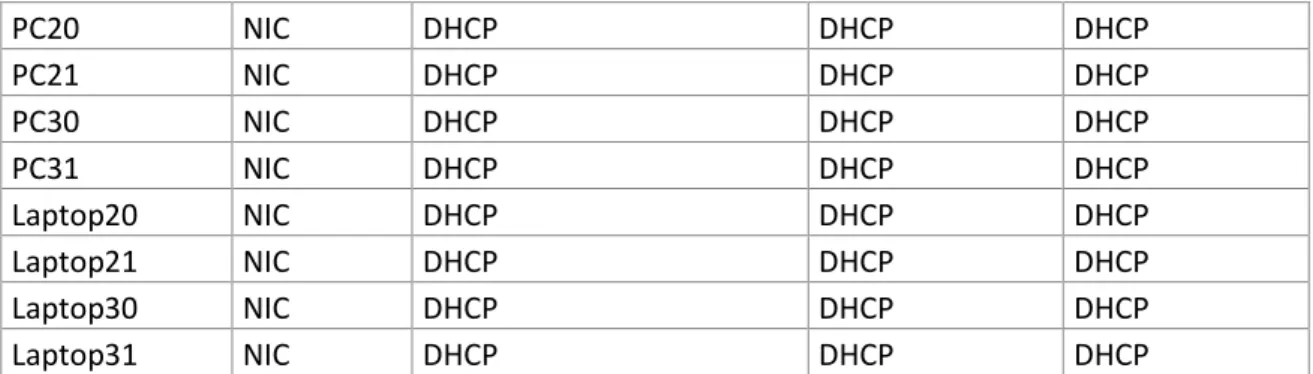
PC20
NIC
DHCP
DHCP
DHCP
PC21
NIC
DHCP
DHCP
DHCP
PC30
NIC
DHCP
DHCP
DHCP
PC31
NIC
DHCP
DHCP
DHCP
Laptop20
NIC
DHCP
DHCP
DHCP
Laptop21
NIC
DHCP
DHCP
DHCP
Laptop30
NIC
DHCP
DHCP
DHCP
Laptop31
NIC
DHCP
DHCP
DHCP
Tabla 2. Direccionamiento de VLAN y de puertos escenario 1
Dispositivo
VLAN
Nombre
Interfaz
SW2
100
LAPTOPS
Fa0/2-3
SW2
200
LAPTOPS
Fa0/4-5
SW3
1
-
Todas las interfaces
Tabla 3. Enlaces troncales escenario 1
Dispositivo
local
Interfaz
Local
Dispositivo
remoto
SW2
Fa0/2-3
100
SITUACIÓN
En esta actividad, demostrará su capacidad de implementar NAT, servidor de
DHCP, RIPV2 y el routing entre VLAN, incluida la configuración de direcciones IP,
las VLAN, los enlaces troncales y las subinterfaces. Todas las pruebas deben
realizarse a través de ping únicamente.
Antes que nada debemos cambiar el hostname a los dispositivos. Esto se hace para
identificar los equipos de manera sencilla:
Router 1
Router>enable
Router#configure terminal
Enter configuration commands, one per line. End with CNTL/Z. Router(config)#hostname R1
R1(config)#
Router 2
12
Router#configure terminalEnter configuration commands, one per line. End with CNTL/Z. Router(config)#hostname R2
R2(config)#
Router 3
Router>enable
Router#configure terminal
Enter configuration commands, one per line. End with CNTL/Z. Router(config)#hostname R3
R3(config)#
Switch 2
Switch>enable
Switch#configure terminal
Enter configuration commands, one per line. End with CNTL/Z. Switch(config)#hostname S2
S2(config)#
Switch 3
Switch>enable
Switch#configure terminal
Enter configuration commands, one per line. End with CNTL/Z. Switch(config)#hostname S3
S3(config)#
DESARROLLO DE ACTIVIDADES
1. SW2 VLAN y las asignaciones de puertos de VLAN deben cumplir con
la tabla 1.
La configuración de VLANs ofrece a la arquitectura de red seguridad y
eficiencia al momento de configurar una red. Es una segmentación utilizada
cuando tenemos una red en la que puede haber una cantidad considerable
de usuarios y/o departamentos. Una buena práctica es que en una empresa
cada departamento tenga una VLAN asignada.
13
Configuración de VLAN en el Switch 2
S2>enable
S2#configure terminal
Enter configuration commands, one per line. End with CNTL/Z. S2(config)#vlan 100
S2(config-vlan)#name LAPTOPS S2(config-vlan)#exit
S2(config)#vlan 200
S2(config-vlan)#name DESTOPS S2(config)#interface range f0/2-3
S2(config-if-range)#switchport mode access S2(config-if-range)#switchport access vlan 100 S2(config-if-range)#interface range f0/4-5 S2(config-if-range)#switchport mode access S2(config-if-range)#switchport access vlan 200 S2(config-if-range)#exit
S2(config)#end S2#
%SYS-5-CONFIG_I: Configured from console by console S2#wr
Building configuration... [OK]
Configuración de la interfaz troncal
S2#configure terminal
Enter configuration commands, one per line. End with CNTL/Z. S2(config)#interface f0/1
S2(config-if)#switchport mode trunk S2(config-if)#exit
S2(config)#end S2#
%SYS-5-CONFIG_I: Configured from console by console S2#wr
Building configuration... [OK]
S2#
Validamos las VLAN de la siguiente manera:
S2#show vlan
VLAN Name Status Ports
---- --- --- --- 1 default active Fa0/1, Fa0/6, Fa0/7, Fa0/8 Fa0/9, Fa0/10, Fa0/11, Fa0/12
Fa0/13, Fa0/14, Fa0/15, Fa0/16 Fa0/17, Fa0/18, Fa0/19, Fa0/20
Fa0/21, Fa0/22, Fa0/23, Fa0/24 100 LAPTOPS active Fa0/2, Fa0/3
14
1002 fddi-default act/unsup 1003 token-ring-default act/unsup 1004 fddinet-default act/unsup 1005 trnet-default act/unsup
VLAN Type SAID MTU Parent RingNo BridgeNo Stp BrdgMode Trans1 Trans2 ---- --- --- ---- --- --- --- ---- --- --- --- 1 enet 100001 1500 - - - - - 0 0 100 enet 100100 1500 - - - - - 0 0 200 enet 100200 1500 - - - - - 0 0 1002 fddi 101002 1500 - - - - - 0 0 1003 tr 101003 1500 - - - - - 0 0 1004 fdnet 101004 1500 - - - ieee- 0 0 1005 trnet 101005 1500 - - - ibm - 0 0
Remote SPAN VLANs
---
Primary Secondary Type Ports
--- --- --- --- S2#
Configuración de VLAN en el Switch 3
S3>enable
S3#configure terminal
Enter configuration commands, one per line. End with CNTL/Z. S3(config)#vlan 1
S3(config-vlan)#exit
S3(config)#interface range f0/1-24
S3(config-if-range)#switchport mode access S3(config-if-range)#switchport access vlan 1 S3(config-if-range)#exit
S3(config)#end S3#
%SYS-5-CONFIG_I: Configured from console by console
S3#wr
Building configuration... [OK]
S3#
Configuración de la interfaz troncal
S3>enable
S3#configure terminal
Enter configuration commands, one per line. End with CNTL/Z. S3(config)#interface f0/1
S3(config-if)#switchport mode trunk S3(config-if)#exit
15
%SYS-5-CONFIG_I: Configured from console by console S3#wr
Building configuration... [OK]
S3#
Validamos las VLAN de la siguiente manera:
S3#show vlan
VLAN Name Status Ports
---- --- --- --- 1 default active Fa0/1, Fa0/2, Fa0/3, Fa0/4
Fa0/5, Fa0/6, Fa0/7, Fa0/8 Fa0/9, Fa0/10, Fa0/11, Fa0/12 Fa0/13, Fa0/14, Fa0/15, Fa0/16 Fa0/17, Fa0/18, Fa0/19, Fa0/20 Fa0/21, Fa0/22, Fa0/23, Fa0/24 1002 fddi-default act/unsup
1003 token-ring-default act/unsup 1004 fddinet-default act/unsup 1005 trnet-default act/unsup
VLAN Type SAID MTU Parent RingNo BridgeNo Stp BrdgMode Trans1 Trans2 ---- --- --- --- --- --- --- --- ---- --- --- 1 enet 100001 1500 - - - - - 0 0 1002 fddi 101002 1500 - - - - - 0 0 1003 tr 101003 1500 - - - - - 0 0 1004 fdnet 101004 1500 - - - ieee - 0 0 1005 trnet 101005 1500 - - - ibm - 0 0
Remote SPAN VLANs
---
Primary Secondary Type Ports
--- --- --- ---S3#
2. Los puertos de red que no se utilizan se deben deshabilitar.
La deshabilitación de los puertos que no se utilizan en una red es una buena
práctica de seguridad ya que cada vez más y con mayor frecuencia personas
ajenas a una red tratarán de conectarse sin permiso y así vulnerar la
seguridad llegando a cometer delitos informáticos como suplantación, robo
de información, secuestro de equipos, entre otros.
16
Deshabilitación de puertos en el Switch 2
S2>enable
S2#configure terminal
Enter configuration commands, one per line. End with CNTL/Z. S2(config)#interface range f0/6-24
S2(config-if-range)#shutdown
%LINK-5-CHANGED: Interface FastEthernet0/6, changed state to administratively down %LINK-5-CHANGED: Interface FastEthernet0/7, changed state to administratively down %LINK-5-CHANGED: Interface FastEthernet0/8, changed state to administratively down %LINK-5-CHANGED: Interface FastEthernet0/9, changed state to administratively down %LINK-5-CHANGED: Interface FastEthernet0/10, changed state to administratively down %LINK-5-CHANGED: Interface FastEthernet0/11, changed state to administratively down %LINK-5-CHANGED: Interface FastEthernet0/12, changed state to administratively down %LINK-5-CHANGED: Interface FastEthernet0/13, changed state to administratively down %LINK-5-CHANGED: Interface FastEthernet0/14, changed state to administratively down %LINK-5-CHANGED: Interface FastEthernet0/15, changed state to administratively down %LINK-5-CHANGED: Interface FastEthernet0/16, changed state to administratively down %LINK-5-CHANGED: Interface FastEthernet0/17, changed state to administratively down %LINK-5-CHANGED: Interface FastEthernet0/18, changed state to administratively down %LINK-5-CHANGED: Interface FastEthernet0/19, changed state to administratively down %LINK-5-CHANGED: Interface FastEthernet0/20, changed state to administratively down %LINK-5-CHANGED: Interface FastEthernet0/21, changed state to administratively down %LINK-5-CHANGED: Interface FastEthernet0/22, changed state to administratively down %LINK-5-CHANGED: Interface FastEthernet0/23, changed state to administratively down %LINK-5-CHANGED: Interface FastEthernet0/24, changed state to administratively down S2(config-if-range)#exit
S2(config)#end S2#
%SYS-5-CONFIG_I: Configured from console by console S2#wr
Building configuration... [OK]
S2#
Deshabilitación de puertos en el Switch 3
S3#enable
S3#configure terminal
Enter configuration commands, one per line. End with CNTL/Z. S3(config)#interface range f0/6-24
S3(config-if-range)#shutdown
17
S3(config)#endS3#
%SYS-5-CONFIG_I: Configured from console by console S3#wr
Building configuration... [OK]
S3#
3. La información de dirección IP R1, R2 y R3 debe cumplir con la tabla 1
Una IP es la forma en que los dispositivos de una red se identifican unos
con otros brindando la funcionalidad para la cual fueron diseñados.
Configuración de las IP en el Router 1
R1>enable
R1#configure terminal
Enter configuration commands, one per line. End with CNTL/Z. R1(config)#interface s0/0/0
R1(config-if)#ip address 200.123.211.2 255.255.255.0 R1(config-if)#exit
R1(config)#interface s0/1/0
R1(config-if)#ip address 10.0.0.1 255.255.255.252 R1(config-if)#exit
R1(config)#interface s0/1/1
R1(config-if)#ip address 10.0.0.5 255.255.255.252 R1(config-if)#end
R1#
%SYS-5-CONFIG_I: Configured from console by console R1#wr
Building configuration... [OK]
R1#
Configuración de las IP en el Router 2
R2>enable
R2#configure terminal
Enter configuration commands, one per line. End with CNTL/Z. R2(config)#interface f0/0.100
R2(config-subif)#encapsulation dot1q 100
R2(config-subif)#ip address 192.168.20.1 255.255.255.0 R2(config-subif)#exit
R2(config)#interface f0/0.200
R2(config-subif)#encapsulation dot1q 200
R2(config-subif)#ip address 192.168.21.1 255.255.255.0 R2(config-subif)#interface s0/0/0
R2(config-if)#ip address 10.0.0.2 255.255.255.252 R2(config-if)#exit
R2(config)#interface s0/0/1
18
R2(config-if)#exitR2(config)#end R2#
%SYS-5-CONFIG_I: Configured from console by console R2#wr
Building configuration... [OK]
R2#
Configuración de las IP en el Router 3
R3>enable
R3#configure terminal
Enter configuration commands, one per line. End with CNTL/Z. R3(config)#interface f0/0
R3(config-if)#ip address 192.168.30.1 255.255.255.0 R3(config-if)#exit
R3(config)#ipv6 unicast-routing R3(config)#interface s0/0/0
R3(config-if)#ip address 10.0.0.6 255.255.255.252 R3(config-if)#exit
R3(config)#interface s0/0/1
R3(config-if)#ip address 10.0.0.10 255.255.255.252 R3(config-if)#exit
R3(config)#end R3#
%SYS-5-CONFIG_I: Configured from console by console R3#wr
Building configuration... [OK]
R3#
4. Laptop20, Laptop21, PC20, PC21, Laptop30, Laptop31, PC30 y PC31
deben obtener información IPv4 del servidor DHCP
19
Figura 2. Configuración DHCP en Laptop20. Imagen propia.
20
Figura 4. Configuración DHCP en PC20. Imagen propia.
21
Figura 6. Configuración DHCP en Laptop30. Imagen propia.
22
Figura 8. Configuración DHCP en PC30. Imagen propia.
23
5. R1 debe realizar una NAT con sobrecarga sobre una dirección IPv4
pública. Asegúrese de que todos los terminales pueden comunicarse
con Internet pública (haga ping a la dirección ISP) y la lista de acceso
estándar se llama INSIDE-DEVS
Con NAT (Network Address Translation – Traducción de direcciones de red)
las redes de utilizan IP privadas por rango y se conecten a la Internet usando
una única dirección IP pública. Esto permite ahorrar costos y direcciones IP
de salida.
La versión con sobrecarga de NAT es PAT (Port Address Translation
–
Traducción de puertos de red) a diferencia de NAT, PAT utiliza los puertos
en lugar de las direcciones IP de este modo un router puede asignar una
misma dirección IP a varias terminales pero la señal es transmitida por
puertos distintos.
R1>enable
R1#configure terminal
Enter configuration commands, one per line. End with CNTL/Z. R1(config)#int s0/1/1
R1(config-if)#ip nat inside R1(config-if)#exit
R1(config)#int s0/1/0
R1(config-if)#ip nat inside R1(config-if)#exit
R1(config)#int s0/0/0
R1(config-if)#ip nat outside R1(config-if)#exit
R1(config)#ip nat pool INSIDE-DEVS 200.123.211.2 200.123.211.128 netmask 255.255.255.0
R1(config)#ip nat pool INSIDE-DEVS 200.123.211.2 200.123.211.128 R1(config)#ip nat R1(config)#ip nat pool INSIDE-DEVS 200.123.211.2 200.123.211.128 netmask 255.255.255.0
R1(config)#access-list 1 permit 192.168.0.0 0.0.255.255 R1(config)#access-list 1 permit 10.0.0.0 0.255.255.255
R1(config)#ip nat inside source list 1 interface s0/0/0 overload
R1(config)#ip nat inside source static tcp 192.168.30.6 80 200.123.211.1 80
R1(config)#exit R1#
%SYS-5-CONFIG_I: Configured from console by console R1#wr
Building configuration... [OK]
24
6. R1 debe tener una ruta estática predeterminada al ISP que se
configuró y que incluye esa ruta en el dominio RIPv2
R1#configure terminal
Enter configuration commands, one per line. End with CNTL/Z. R1(config)#router rip R1(config-router)#version 2 R1(config-router)#network 10.0.0.0 R1(config-router)#exit R1(config)#end R1#
%SYS-5-CONFIG_I: Configured from console by console R1#wr
Building configuration... [OK]
R1#
7. R2 es un servidor de DHCP para los dispositivos conectados al puerto
FastEthernet0/0
R2>enable
R2#configure terminal
Enter configuration commands, one per line. End with CNTL/Z. R2(config)#ip dhcp excluded-address 10.0.0.2 10.0.0.9
R2(config)#ip dhcp pool INSIDE-DEVS
R2(dhcp-config)#network 192.168.20.1 255.255.255.0 R2(dhcp-config)#network 192.168.21.1 255.255.255.0 R2(dhcp-config)#default-router 192.168.1.1
R2(dhcp-config)#dns-server 0.0.0.0 R2(dhcp-config)#exit
R2(config)#exit R2#
%SYS-5-CONFIG_I: Configured from console by console R2#wr
Building configuration... [OK]
R2#
8. R2 debe, además de enrutamiento a otras partes de la red, ruta entre
las VLAN 100 y 200
R2#configure terminal
Enter configuration commands, one per line. End with CNTL/Z. R2(config)#int vlan 100
R2(config-if)#ip address 192.168.20.1 255.255.255.0 % 192.168.20.0 overlaps with FastEthernet0/0.100 R2(config-if)#exit
R2(config)#int vlan 200
25
R2(config-if)#exitR2(config)#end R2#
%SYS-5-CONFIG_I: Configured from console by console R2#wr
Building configuration... [OK]
R2#
9. El Servidor0 es sólo un servidor IPv6 y solo debe ser accesibles para
los dispositivos en R3 (ping)
Figura 10. Configuración DHCPv6 en Server0. Imagen propia.
26
10. La NIC instalado en direcciones IPv4 e IPv6 de Laptop30, de Laptop31,
de PC30 y obligación de configurados PC31 simultáneas (dual-stack).
Las direcciones se deben configurar mediante DHCP y DHCPv6
Figura 12. Configuración de DHCPv6 en Laptop30. Imagen propia.
11. La interfaz FastEthernet 0/0 del R3 también deben tener direcciones
IPv4 e IPv6 configuradas (dual- stack)
El RIP (Routing Information Protocol
– Protocolo de información de ruteo)
permite calcular la mejor ruta para la transmisión de paquetes. Esto lo hace
por medio de saltos, cada salto es un dispositivo por el que un paquete de
datos pasa para llegar a su destino y lo usa como métrica por medio de un
timer para designar la ruta más corta entre ellos.
R3>enable
R3#configure terminal
Enter configuration commands, one per line. End with CNTL/Z. R3(config)#ipv6 unicast-routing
R3(config)#interface f0/0 R3(config-if)#ipv6 enable
R3(config-if)#ip address 192.168.30.1 255.255.255.0 R3(config-if)#ipv6 address 2001:db8:130::9C0:80F:301/64 R3(config-if)#no shutdown
R3(config-if)#
27
%LINEPROTO-5-UPDOWN: Line protocol on Interface FastEthernet0/0, changed state to up
R3(config-if)#exit R3(config)#end R3#
%SYS-5-CONFIG_I: Configured from console by console
R3#wr
Building configuration... [OK]
R3#
12. R1, R2 y R3 intercambian información de routing mediante RIP versión 2.
Configuración para R1
R1>enable
R1#configure terminal
Enter configuration commands, one per line. End with CNTL/Z. R1(config)#router rip
R1(config-router)#version 2
R1(config-router)#network 10.0.0.0 R1(config-router)#network 10.0.0.4 R1(config-router)#end
R1#
%SYS-5-CONFIG_I: Configured from console by console R1#wr
Building configuration... [OK]
R1#
Configuración para R2
R2>enable
R2#configure terminal
Enter configuration commands, one per line. End with CNTL/Z. R2(config)#router rip
R2(config-router)#version 2
R2(config-router)#network 10.0.0.0 R2(config-router)#network 10.0.0.8 R2(config-router)#end
R2#
%SYS-5-CONFIG_I: Configured from console by console R2#wr
Building configuration... [OK]
28
Configuración para R3
R3>enable
R3#configure terminal
Enter configuration commands, one per line. End with CNTL/Z. R3(config)#router rip
R3(config-router)#version 2
R3(config-router)#network 10.0.0.0 R3(config-router)#network 10.0.0.8 R3(config-router)#end
R3#
%SYS-5-CONFIG_I: Configured from console by console
R3#wr
Building configuration... [OK]
R3#
13. R1, R2 y R3 deben saber sobre las rutas de cada uno y la ruta
predeterminada desde R1.
Comprobación para R1
R1#show ip route
Codes: C - connected, S - static, I - IGRP, R - RIP, M - mobile, B - BGP D - EIGRP, EX - EIGRP external, O - OSPF, IA - OSPF inter area
N1 - OSPF NSSA external type 1, N2 - OSPF NSSA external type 2 E1 - OSPF external type 1, E2 - OSPF external type 2, E - EGP
i - IS-IS, L1 - IS-IS level-1, L2 - IS-IS level-2, ia - IS-IS inter area * - candidate default, U - per-user static route, o - ODR
P - periodic downloaded static route
Gateway of last resort is not set R1#
Comprobación para R2
R2#show ip route
Codes: C - connected, S - static, I - IGRP, R - RIP, M - mobile, B - BGP D - EIGRP, EX - EIGRP external, O - OSPF, IA - OSPF inter area
N1 - OSPF NSSA external type 1, N2 - OSPF NSSA external type 2 E1 - OSPF external type 1, E2 - OSPF external type 2, E - EGP
i - IS-IS, L1 - IS-IS level-1, L2 - IS-IS level-2, ia - IS-IS inter area * - candidate default, U - per-user static route, o - ODR
P - periodic downloaded static route Gateway of last resort is not set R2#
Comprobación para R3
29
Codes: C - connected, S - static, I - IGRP, R - RIP, M - mobile, B - BGP D - EIGRP, EX - EIGRP external, O - OSPF, IA - OSPF inter area
N1 - OSPF NSSA external type 1, N2 - OSPF NSSA external type 2 E1 - OSPF external type 1, E2 - OSPF external type 2, E - EGP
i - IS-IS, L1 - IS-IS level-1, L2 - IS-IS level-2, ia - IS-IS inter area * - candidate default, U - per-user static route, o - ODR
P - periodic downloaded static route Gateway of last resort is not set
C 192.168.30.0/24 is directly connected, FastEthernet0/0 R3#
14. Verifique la conectividad. Todos los terminales deben poder hacer
ping entre sí y a la dirección IP del ISP. Los terminales bajo el R3
deberían poder hacer IPv6-ping entre ellos y el servidor
Comprobación de ping al servidor por medio de IPv6
30
Figura 14. Comprobación de ping IPv6 en Laptop31. Imagen propia.
31
Figura 16. Comprobación de ping IPv6 en PC31. Imagen propia.
32
Figura 18. Conectividad mediante ping IPv4 en Laptop31. Imagen propia.
33
Figura 20. Conectividad mediante ping IPv4 en PC30. Imagen propia.
34
Figura 22. Conectividad mediante ping IPv4 en PC20. Imagen propia.
35
Figura 24. Conectividad mediante ping IPv4 en Laptop21. Imagen propia.
Figura 25. Conectividad mediante ping IPv4 en Laptop20. Imagen propia.
36
ESCENARIO 2
Una empresa de Tecnología posee tres sucursales distribuidas en las ciudades de
Miami, Bogotá y Buenos Aires, en donde el estudiante será el administrador de la
red, el cual deberá configurar e interconectar entre sí cada uno de los dispositivos
que forman parte del escenario, acorde con los lineamientos establecidos para el
direccionamiento IP, protocolos de enrutamiento y demás aspectos que forman
parte de la topología de red.
Topología propuesta
Figura 27. Topología propuesta escenario 2. Prueba de habilidades prácticas CCNA
Tabla 4. VLAN Escenario 2
VLAN
Direccionamiento
Nombre
37
1. Configurar el direccionamiento IP acorde con la topología de red para
cada uno de los dispositivos que forman parte del escenario.
Direccionamiento en Internet-PC
Figura 28. Asignación de IPv4 en Internet-PC. Imagen propia.
Direccionamiento en R1
Router>enable
Router#configure terminal
Enter configuration commands, one per line. End with CNTL/Z. Router(config)#hostname R1
R1(config)#interface s0/0/0
R1(config-if)#description connection to R2
R1(config-if)#ip address 172.31.21.1 255.255.255.252 R1(config-if)#clock rate 128000
This command applies only to DCE interfaces R1(config-if)#exit
R1(config)#interface Serial0/0/0 R1(config-if)#clock rate 128000 R1(config-if)#no shutdown
R1(config-if)#exit
R1(config)#ip route 0.0.0.0 0.0.0.0 s0/0/0 R1(config)#end
%SYS-5-CONFIG_I: Configured from console by console R1#wr
Building configuration... [OK]
38
Direccionamiento en R2
Router>enable
Router#configure terminal
Enter configuration commands, one per line. End with CNTL/Z. Router(config)#hostname R2
R2(config)#interface s0/0/0
R2(config-if)#description Connection to R1
R2(config-if)#ip address 172.31.21.2 255.255.255.252 R2(config-if)#no shutdown
R2(config-if)#interface s0/0/1
R2(config-if)#description Connection to R3
R2(config-if)#ip address 172.31.23.1 255.255.255.252 R2(config-if)#clock rate 128000
This command applies only to DCE interfaces R2(config-if)#no shutdown
R2(config-if)#interface f0/0
R2(config-if)#description connection to ISP
R2(config-if)#ip address 209.165.200.225 255.255.255.248 R2(config-if)#no shutdown
R2(config-if)#interface f0/1
R2(config-if)#ip address 10.10.10.1 255.255.255.0 R2(config-if)#description connection to WebServer R2(config-if)#no shutdown
R2(config)#ip route 0.0.0.0 0.0.0.0 f0/0 R2(config-if)#exit
R2(config)#end R2#
%SYS-5-CONFIG_I: Configured from console by console R2#wr
Building configuration... [OK]
R2#
Direccionamiento en WebServer
39
Direccionamiento en R3
Router>enable
Router#configure terminal
Enter configuration commands, one per line. End with CNTL/Z. Router(config)#hostname R3
R3(config)#interface s0/0/1
R3(config-if)#description connection to R2
R3(config-if)#ip address 172.31.23.2 255.255.255.252 R3(config-if)#no shutdown
R3(config-if)#interface lo4 R3(config-if)#
%LINK-5-CHANGED: Interface Loopback4, changed state to up
%LINEPROTO-5-UPDOWN: Line protocol on Interface Loopback4, changed state to up
R3(config-if)#ip address 192.168.4.1 255.255.255.0 R3(config-if)#no shutdown
R3(config-if)#interface lo5 R3(config-if)#
%LINK-5-CHANGED: Interface Loopback5, changed state to up
%LINEPROTO-5-UPDOWN: Line protocol on Interface Loopback5, changed state to up
R3(config-if)#ip address 192.168.5.1 255.255.255.0 R3(config-if)#no shutdown
R3(config-if)#interface lo6 R3(config-if)#
%LINK-5-CHANGED: Interface Loopback6, changed state to up
%LINEPROTO-5-UPDOWN: Line protocol on Interface Loopback6, changed state to up
R3(config-if)#ip address 192.168.6.1 255.255.255.0 R3(config-if)#no shutdown
R3(config-if)#exit
R3(config)#ip route 0.0.0.0 0.0.0.0 s0/0/1 R3(config)#end
R3#
%SYS-5-CONFIG_I: Configured from console by console R3#wr
Building configuration... [OK]
R3#
Direccionamiento en S1
Switch>enable
Switch#configure terminal
Enter configuration commands, one per line. End with CNTL/Z. Switch(config)#hostname S1
S1(config)#exit S1#
%SYS-5-CONFIG_I: Configured from console by console S1#wr
Building configuration... [OK]
40
Direccionamiento en S3
Switch>enable
Switch#configure terminal
Enter configuration commands, one per line. End with CNTL/Z. Switch(config)#hostname S3
S3(config)#exit S3#
%SYS-5-CONFIG_I: Configured from console by console S3#wr
Building configuration... [OK]
S3#
2. Configurar el protocolo de enrutamiento OSPFv2 bajo los siguientes
criterios:
El OSPF (Open Shortest Path First - El camino más corto primero) tiene el
mismo funcionamiento que RIP pero en en la parte interna de las redes, para
ello cada router aprende cual es su vecino más cercano y así determinar la
ruta idónea de transmisión.
Tabla 5. OSPFv2 area 0 en escenario 2
Configuration Item of Task
Specification
Router ID R1
1.1.1.1
Router ID R2
5.5.5.5
Router ID R3
8.8.8.8
Configurar todas las interfaces LAN como pasivas
Establecer el ancho de banda para enlaces seriales en
256 Kb/s
Ajustar el costo en la métrica de S0/0 a
9500
OSPF en R1
R1#configure terminal
Enter configuration commands, one per line. End with CNTL/Z. R1(config)#router ospf 1
R1(config-router)#router-id 1.1.1.1
R1(config-router)#network 172.31.21.0 0.0.0.3 area 0 R1(config-router)#network 172.168.30.0 0.0.0.255 area 0 R1(config-router)#network 172.168.40.0 0.0.0.255 area 0 R1(config-router)#network 172.168.200.0 0.0.0.255 area 0 R1(config-router)#passive-interface f0/0.30
R1(config-router)#passive-interface f0/0.40 R1(config-router)#passive-interface f0/0.200 R1(config-router)#exit
41
R1(config-if)#ip ospf cost 9500R1(config-if)#exit R1(config)#end R1#
%SYS-5-CONFIG_I: Configured from console by console R1#wr
Building configuration... [OK]
R1#
OSPF en R2
R2#configure terminal
Enter configuration commands, one per line. End with CNTL/Z. R2(config)#router ospf 1
R2(config-router)#router-id 5.5.5.5
R2(config-router)#network 172.31.21.0 0.0.0.3 area 0 R2(config-router)#network 172.31.23.0 0.0.0.3 area 0 R2(config-router)#network 10.10.10.10 0.0.0.255 area 0 R2(config-router)#passive-interface f0/1
R2(config-router)#interface s0/0/0 R2(config-if)#bandwidth 256
R2(config-if)#ip ospf cost 9500 R2(config-if)#exit
R2(config)#end R2#
%SYS-5-CONFIG_I: Configured from console by console R2#wr
Building configuration... [OK]
R2#
OSPF en R3
R3>enable
R3#configure terminal
Enter configuration commands, one per line. End with CNTL/Z. R3(config)#router ospf 1
R3(config-router)#router-id 8.8.8.8
R3(config-router)#network 172.16.23.0 0.0.0.3 area 0 R3(config-router)#network 192.168.4.0 0.0.0.255 area 0 R3(config-router)#passive-interface lo4 R3(config-router)#passive-interface lo5 R3(config-router)#passive-interface lo6 R3(config-router)#exit R3(config)#interface s0/0/1 R3(config-if)#bandwidth 256 R3(config-if)#exit R3(config)#end R3#
%SYS-5-CONFIG_I: Configured from console by console R3#wr
Building configuration... [OK]
42
Verificar información de OSPF
Visualizar tablas de enrutamiento y routers conectados por OSPFv2.
Verificación en R2
R2#show ip ospf
Routing Process "ospf 1" with ID 5.5.5.5 Supports only single TOS(TOS0) routes Supports opaque LSA
SPF schedule delay 5 secs, Hold time between two SPFs 10 secs Minimum LSA interval 5 secs. Minimum LSA arrival 1 secs
Number of external LSA 0. Checksum Sum 0x000000 Number of opaque AS LSA 0. Checksum Sum 0x000000 Number of DCbitless external and opaque AS LSA 0 Number of DoNotAge external and opaque AS LSA 0
Number of areas in this router is 1. 1 normal 0 stub 0 nssa External flood list length 0
Area BACKBONE(0)
Number of interfaces in this area is 3 Area has no authentication
SPF algorithm executed 5 times Area ranges are
Number of LSA 1. Checksum Sum 0x006842
Number of opaque link LSA 0. Checksum Sum 0x000000 Number of DCbitless LSA 0
Number of indication LSA 0 Number of DoNotAge LSA 0 Flood list length 0
R2#
Verificación en R1
R1#show ip ospf
Routing Process "ospf 1" with ID 1.1.1.1 Supports only single TOS(TOS0) routes Supports opaque LSA
SPF schedule delay 5 secs, Hold time between two SPFs 10 secs Minimum LSA interval 5 secs. Minimum LSA arrival 1 secs
Number of external LSA 0. Checksum Sum 0x000000 Number of opaque AS LSA 0. Checksum Sum 0x000000 Number of DCbitless external and opaque AS LSA 0 Number of DoNotAge external and opaque AS LSA 0
Number of areas in this router is 1. 1 normal 0 stub 0 nssa External flood list length 0
Area BACKBONE(0)
Number of interfaces in this area is 1 Area has no authentication
SPF algorithm executed 5 times Area ranges are
43
Number of opaque link LSA 0. Checksum Sum 0x000000 Number of DCbitless LSA 0
Number of indication LSA 0 Number of DoNotAge LSA 0 Flood list length 0 R1#
Verificación en R3
R3#show ip ospf
Routing Process "ospf 1" with ID 8.8.8.8 Supports only single TOS(TOS0) routes Supports opaque LSA
SPF schedule delay 5 secs, Hold time between two SPFs 10 secs Minimum LSA interval 5 secs. Minimum LSA arrival 1 secs
Number of external LSA 0. Checksum Sum 0x000000 Number of opaque AS LSA 0. Checksum Sum 0x000000 Number of DCbitless external and opaque AS LSA 0 Number of DoNotAge external and opaque AS LSA 0
Number of areas in this router is 1. 1 normal 0 stub 0 nssa External flood list length 0
Area BACKBONE(0)
Number of interfaces in this area is 1 Area has no authentication
SPF algorithm executed 1 times Area ranges are
Number of LSA 1. Checksum Sum 0x005154
Number of opaque link LSA 0. Checksum Sum 0x000000 Number of DCbitless LSA 0
Number of indication LSA 0 Number of DoNotAge LSA 0 Flood list length 0
R3#
Visualizar lista resumida de interfaces por OSPF en donde se ilustre el costo
de cada interface
Validación en R1
R1#show ip ospf interface
Serial0/0/0 is up, line protocol is up Internet address is 172.31.21.1/30, Area 0
Process ID 1, Router ID 1.1.1.1, Network Type POINT-TO-POINT, Cost: 9500 Transmit Delay is 1 sec, State POINT-TO-POINT, Priority 0
No designated router on this network
No backup designated router on this network
Timer intervals configured, Hello 10, Dead 40, Wait 40, Retransmit 5 Hello due in 00:00:04
44
Last flood scan length is 1, maximum is 1Last flood scan time is 0 msec, maximum is 0 msec Suppress hello for 0 neighbor(s)
R1#
Validación en R2
R2#show ip ospf interface
Serial0/0/0 is up, line protocol is up Internet address is 172.31.21.2/30, Area 0
Process ID 1, Router ID 5.5.5.5, Network Type POINT-TO-POINT, Cost: 9500 Transmit Delay is 1 sec, State POINT-TO-POINT, Priority 0
No designated router on this network
No backup designated router on this network
Timer intervals configured, Hello 10, Dead 40, Wait 40, Retransmit 5 Hello due in 00:00:02
Index 1/1, flood queue length 0 Next 0x0(0)/0x0(0)
Last flood scan length is 1, maximum is 1
Last flood scan time is 0 msec, maximum is 0 msec Suppress hello for 0 neighbor(s)
Serial0/0/1 is up, line protocol is up Internet address is 172.31.23.1/30, Area 0
Process ID 1, Router ID 5.5.5.5, Network Type POINT-TO-POINT, Cost: 64 Transmit Delay is 1 sec, State POINT-TO-POINT, Priority 0
No designated router on this network
No backup designated router on this network
Timer intervals configured, Hello 10, Dead 40, Wait 40, Retransmit 5 Hello due in 00:00:08
R2#
Validación en R3
R3#show ip ospf interface
Loopback4 is up, line protocol is up
Internet address is 192.168.4.1/24, Area 0
Process ID 1, Router ID 8.8.8.8, Network Type LOOPBACK, Cost: 1 Loopback interface is treated as a stub Host
R3#
Visualizar el OSPF Process ID, Router ID, Address summarizations, Routing
Networks, and passive interfaces configuradas en cada router
Validación en R1
R1#show ip protocols
Routing Protocol is "ospf 1"
45
Incoming update filter list for all interfaces is not set Router ID 1.1.1.1
Number of areas in this router is 1. 1 normal 0 stub 0 nssa Maximum path: 4
Routing for Networks: 172.31.21.0 0.0.0.3 area 0 172.168.30.0 0.0.0.255 area 0 172.168.40.0 0.0.0.255 area 0 172.168.200.0 0.0.0.255 area 0 Passive Interface(s):
FastEthernet0/0.40 FastEthernet0/0.30 FastEthernet0/0.200
Routing Information Sources: Gateway Distance Last Update 1.1.1.1 110 00:04:30
Distance: (default is 110) R1#
Validación en R2
R2#show ip protocols
Routing Protocol is "ospf 1"
Outgoing update filter list for all interfaces is not set Incoming update filter list for all interfaces is not set Router ID 5.5.5.5
Number of areas in this router is 1. 1 normal 0 stub 0 nssa Maximum path: 4
Routing for Networks: 172.31.21.0 0.0.0.3 area 0 172.31.23.0 0.0.0.3 area 0 10.10.10.0 0.0.0.255 area 0 Passive Interface(s): FastEthernet0/1
Routing Information Sources: Gateway Distance Last Update 5.5.5.5 110 00:25:37
Distance: (default is 110) R2#
Validación en R3
R3#show ip protocols
Routing Protocol is "ospf 1"
Outgoing update filter list for all interfaces is not set Incoming update filter list for all interfaces is not set Router ID 8.8.8.8
Number of areas in this router is 1. 1 normal 0 stub 0 nssa Maximum path: 4
46
Loopback4Loopback5 Loopback6
Routing Information Sources: Gateway Distance Last Update 8.8.8.8 110 00:20:37
Distance: (default is 110) R3#
3. Configurar VLANs, Puertos troncales, puertos de acceso,
encapsulamiento, Inter-VLAN Routing y Seguridad en los Switches
acorde a la topología de red establecida.
Configuración en S1
S1>enable
S1#configure terminal
Enter configuration commands, one per line. End with CNTL/Z. S1(config)#vlan 30 S1(config-vlan)#name Administracion S1(config-vlan)#vlan 40 S1(config-vlan)#name Mercadeo S1(config-vlan)#vlan 200 S1(config-vlan)#name Mantenimiento S1(config-vlan)#exit
S1(config)#interface vlan 200 S1(config-if)#
%LINK-5-CHANGED: Interface Vlan200, changed state to up S1(config-if)#ip address 192.168.200.2 255.255.255.0 S1(config-if)#no shutdown
S1(config-if)#exit
S1(config)#ip default-gateway 192.168.200.1 S1(config)#interface f0/03
S1(config-if)#interface f0/3
S1(config-if)#switchport mode trunk S1(config-if)#
%LINEPROTO-5-UPDOWN: Line protocol on Interface FastEthernet0/3, changed state to down %LINEPROTO-5-UPDOWN: Line protocol on Interface FastEthernet0/3, changed state to up %LINEPROTO-5-UPDOWN: Line protocol on Interface Vlan200, changed state to up
S1(config-if)#switchport trunk native vlan 1 S1(config-if)#interface f0/5
S1(config-if)#switchport mode trunk
S1(config-if)#switchport trunk native vlan 1
S1(config-if-range)#interface range f0/1-2, f0/4, f0/6-24, g0/1-2 S1(config-if-range)#switchport mode access
S1(config-if-range)#interface f0/6 S1(config-if)#switchport mode access S1(config-if)#switchport access vlan 30
S1(config-if)#interface range f0/1-2, f0/4, f0/7-23, g0/1-2 S1(config-if-range)#shutdown
47
%LINK-5-CHANGED: Interface FastEthernet0/8, changed state to administratively down %LINK-5-CHANGED: Interface FastEthernet0/9, changed state to administratively down %LINK-5-CHANGED: Interface FastEthernet0/10, changed state to administratively down %LINK-5-CHANGED: Interface FastEthernet0/11, changed state to administratively down %LINK-5-CHANGED: Interface FastEthernet0/12, changed state to administratively down %LINK-5-CHANGED: Interface FastEthernet0/13, changed state to administratively down %LINK-5-CHANGED: Interface FastEthernet0/14, changed state to administratively down %LINK-5-CHANGED: Interface FastEthernet0/15, changed state to administratively down %LINK-5-CHANGED: Interface FastEthernet0/16, changed state to administratively down %LINK-5-CHANGED: Interface FastEthernet0/17, changed state to administratively down %LINK-5-CHANGED: Interface FastEthernet0/18, changed state to administratively down %LINK-5-CHANGED: Interface FastEthernet0/19, changed state to administratively down %LINK-5-CHANGED: Interface FastEthernet0/20, changed state to administratively down %LINK-5-CHANGED: Interface FastEthernet0/21, changed state to administratively down %LINK-5-CHANGED: Interface FastEthernet0/22, changed state to administratively down %LINK-5-CHANGED: Interface FastEthernet0/23, changed state to administratively down %LINK-5-CHANGED: Interface GigabitEthernet0/1, changed state to administratively down %LINK-5-CHANGED: Interface GigabitEthernet0/2, changed state to administratively down S1(config-if-range)#exit
S1(config)#end S1#
%SYS-5-CONFIG_I: Configured from console by console S1#wr
Building configuration... [OK]
S1# S1#
Configuración en S3
S3>enable
S3#configure terminal
Enter configuration commands, one per line. End with CNTL/Z. S3(config)#vlan 30 S3(config-vlan)#name Administracion S3(config-vlan)#vlan 40 S3(config-vlan)#name Mercadeo S3(config-vlan)#vlan 200 S3(config-vlan)#name Mantenimiento S3(config-vlan)#exit
S3(config)#interface vlan 200 S3(config-if)#
%LINK-5-CHANGED: Interface Vlan200, changed state to up
%LINEPROTO-5-UPDOWN: Line protocol on Interface Vlan200, changed state to up S3(config-if)#ip address 192.168.200.3 255.255.255.0
S3(config-if)#no shutdown S3(config-if)#exit
S3(config)#ip default-gateway 192.168.200.1 S3(config)#interface f0/3
S3(config-if)#switchport mode trunk
S3(config-if)#switchport trunk native vlan 1
S3(config-if)#interface range f0/1-2, f0/4-24, g0/1-2 S3(config-if-range)#switchport mode access
S3(config-if-range)#interface f0/3 S3(config-if)#switchport mode access S3(config-if)#
48
S3(config-if)#interface range f0/2, f0/4-24, g0/1-2 S3(config-if-range)#shutdown
%LINK-5-CHANGED: Interface FastEthernet0/2, changed state to administratively down %LINK-5-CHANGED: Interface FastEthernet0/4, changed state to administratively down %LINK-5-CHANGED: Interface FastEthernet0/5, changed state to administratively down %LINK-5-CHANGED: Interface FastEthernet0/6, changed state to administratively down %LINK-5-CHANGED: Interface FastEthernet0/7, changed state to administratively down %LINK-5-CHANGED: Interface FastEthernet0/8, changed state to administratively down %LINK-5-CHANGED: Interface FastEthernet0/9, changed state to administratively down %LINK-5-CHANGED: Interface FastEthernet0/10, changed state to administratively down %LINK-5-CHANGED: Interface FastEthernet0/11, changed state to administratively down %LINK-5-CHANGED: Interface FastEthernet0/12, changed state to administratively down %LINK-5-CHANGED: Interface FastEthernet0/13, changed state to administratively down %LINK-5-CHANGED: Interface FastEthernet0/14, changed state to administratively down %LINK-5-CHANGED: Interface FastEthernet0/15, changed state to administratively down %LINK-5-CHANGED: Interface FastEthernet0/16, changed state to administratively down %LINK-5-CHANGED: Interface FastEthernet0/17, changed state to administratively down %LINK-5-CHANGED: Interface FastEthernet0/18, changed state to administratively down %LINK-5-CHANGED: Interface FastEthernet0/19, changed state to administratively down %LINK-5-CHANGED: Interface FastEthernet0/20, changed state to administratively down %LINK-5-CHANGED: Interface FastEthernet0/21, changed state to administratively down %LINK-5-CHANGED: Interface FastEthernet0/22, changed state to administratively down %LINK-5-CHANGED: Interface FastEthernet0/23, changed state to administratively down %LINK-5-CHANGED: Interface FastEthernet0/24, changed state to administratively down %LINK-5-CHANGED: Interface GigabitEthernet0/1, changed state to administratively down %LINK-5-CHANGED: Interface GigabitEthernet0/2, changed state to administratively down S3(config-if-range)#exit
S3(config)#end S3#
%SYS-5-CONFIG_I: Configured from console by console S3#wr
Building configuration... [OK]
S3#
Configuración en R1
R1>enable
R1#configure terminal
Enter configuration commands, one per line. End with CNTL/Z. R1(config)#interface f0/0.40
R1(config-subif)#
R1(config-subif)#interface f0/0.30 R1(config-subif)#
%LINK-5-CHANGED: Interface FastEthernet0/0.30, changed state to up %LINEPROTO-5-UPDOWN: Line protocol on Interface FastEthernet0/0.30, changed state to up R1(config-subif)#description Administracion LAN
R1(config-subif)#encapsulation dot1q 30
R1(config-subif)#ip address 192.168.30.1 255.255.255.0 R1(config-subif)#interface f0/0.10
R1(config-subif)#
%LINK-5-CHANGED: Interface FastEthernet0/0.10, changed state to up %LINEPROTO-5-UPDOWN: Line protocol on Interface FastEthernet0/0.10, changed state to up R1(config-subif)#interface f0/0.40
R1(config-subif)#description Mercadeo LAN R1(config-subif)#encapsulation dot1q 40
R1(config-subif)#ip address 192.168.40.1 255.255.255.0 R1(config-subif)#interface f0/0.200
49
%LINK-5-CHANGED: Interface FastEthernet0/0.200, changed state to up %LINEPROTO-5-UPDOWN: Line protocol on Interface FastEthernet0/0.200, changed state to up R1(config-subif)#description Mantenimiento LAN
R1(config-subif)#encapsulation dot1q 200
R1(config-subif)#ip address 192.168.200.1 255.255.255.0 R1(config-subif)#interface f0/0
R1(config-if)#no shutdown R1(config-if)#exit
R1(config)#end R1#
%SYS-5-CONFIG_I: Configured from console by console R1#wr
Building configuration... [OK]
R1#
4. En el Switch 3 deshabilitar DNS lookup
S3>enable
S3#configure terminal
Enter configuration commands, one per line. End with CNTL/Z. S3(config)#no ip domain-lookup
S3(config)#exit S3#
%SYS-5-CONFIG_I: Configured from console by console S3#wr
Building configuration... [OK]
S3#
5. Asignar direcciones IP a los Switches acorde a los lineamientos
Asignación en S1
S1#show ip interface
Vlan1 is administratively down, line protocol is down Internet protocol processing disabled
Vlan200 is up, line protocol is up Internet address is 192.168.200.2/24 Broadcast address is 255.255.255.255 S1#
Asignación en S3
S3#show ip interface
Vlan1 is administratively down, line protocol is down Internet protocol processing disabled
50
6. Desactivar todas las interfaces que no sean utilizadas en el esquema
de red
Aplicación en R1
R1>enable
R1#configure terminal
Enter configuration commands, one per line. End with CNTL/Z. R1(config)#interface f0/1
R1(config-if)#interface range f0/1 R1(config-if-range)#shutdown
R1(config-if-range)#exit R1(config)#end
R1#
%SYS-5-CONFIG_I: Configured from console by console R1#wr
Building configuration... [OK]
R1#
Aplicación en R2
R2>enable
R2#configure terminal
Enter configuration commands, one per line. End with CNTL/Z. R2(config)#interface Serial0/1/0 R2(config-if)#shutdown R2(config-if)#interface Serial0/1/1 R2(config-if)#shutdown R2(config-if)#exit R2(config)#end R2#
%SYS-5-CONFIG_I: Configured from console by console R2#wr
Building configuration... [OK]
R2#
Aplicación en R3
R3>enable
R3#configure terminal
51
R3#%SYS-5-CONFIG_I: Configured from console by console R3#wr
Building configuration... [OK]
R3#
Aplicación en S1
S1>enable
S1#configure terminal
Enter configuration commands, one per line. End with CNTL/Z. S1(config-if)#interface range f0/1-2, f0/4, f0/7-23, g0/1-2 S1(config-if-range)#shutdown
%LINK-5-CHANGED: Interface FastEthernet0/2, changed state to administratively down %LINK-5-CHANGED: Interface FastEthernet0/4, changed state to administratively down %LINK-5-CHANGED: Interface FastEthernet0/7, changed state to administratively down %LINK-5-CHANGED: Interface FastEthernet0/8, changed state to administratively down %LINK-5-CHANGED: Interface FastEthernet0/9, changed state to administratively down %LINK-5-CHANGED: Interface FastEthernet0/10, changed state to administratively down %LINK-5-CHANGED: Interface FastEthernet0/11, changed state to administratively down %LINK-5-CHANGED: Interface FastEthernet0/12, changed state to administratively down %LINK-5-CHANGED: Interface FastEthernet0/13, changed state to administratively down %LINK-5-CHANGED: Interface FastEthernet0/14, changed state to administratively down %LINK-5-CHANGED: Interface FastEthernet0/15, changed state to administratively down %LINK-5-CHANGED: Interface FastEthernet0/16, changed state to administratively down %LINK-5-CHANGED: Interface FastEthernet0/17, changed state to administratively down %LINK-5-CHANGED: Interface FastEthernet0/18, changed state to administratively down %LINK-5-CHANGED: Interface FastEthernet0/19, changed state to administratively down %LINK-5-CHANGED: Interface FastEthernet0/20, changed state to administratively down %LINK-5-CHANGED: Interface FastEthernet0/21, changed state to administratively down %LINK-5-CHANGED: Interface FastEthernet0/22, changed state to administratively down %LINK-5-CHANGED: Interface FastEthernet0/23, changed state to administratively down %LINK-5-CHANGED: Interface GigabitEthernet0/1, changed state to administratively down %LINK-5-CHANGED: Interface GigabitEthernet0/2, changed state to administratively down S1(config-if-range)#exit
S1(config)#end S1#
%SYS-5-CONFIG_I: Configured from console by console S1#wr
Building configuration... [OK]
S1#
Aplicación en S3
S3>enable
S3#configure terminal
Enter configuration commands, one per line. End with CNTL/Z. S3(config-if)#interface range f0/2, f0/4-24, g0/1-2
S3(config-if-range)#shutdown
52
%LINK-5-CHANGED: Interface FastEthernet0/11, changed state to administratively down %LINK-5-CHANGED: Interface FastEthernet0/12, changed state to administratively down %LINK-5-CHANGED: Interface FastEthernet0/13, changed state to administratively down %LINK-5-CHANGED: Interface FastEthernet0/14, changed state to administratively down %LINK-5-CHANGED: Interface FastEthernet0/15, changed state to administratively down %LINK-5-CHANGED: Interface FastEthernet0/16, changed state to administratively down %LINK-5-CHANGED: Interface FastEthernet0/17, changed state to administratively down %LINK-5-CHANGED: Interface FastEthernet0/18, changed state to administratively down %LINK-5-CHANGED: Interface FastEthernet0/19, changed state to administratively down %LINK-5-CHANGED: Interface FastEthernet0/20, changed state to administratively down %LINK-5-CHANGED: Interface FastEthernet0/21, changed state to administratively down %LINK-5-CHANGED: Interface FastEthernet0/22, changed state to administratively down %LINK-5-CHANGED: Interface FastEthernet0/23, changed state to administratively down %LINK-5-CHANGED: Interface FastEthernet0/24, changed state to administratively down %LINK-5-CHANGED: Interface GigabitEthernet0/1, changed state to administratively down %LINK-5-CHANGED: Interface GigabitEthernet0/2, changed state to administratively down S3(config-if-range)#exit
S3(config)#end S3#
%SYS-5-CONFIG_I: Configured from console by console S3#wr
Building configuration... [OK]
S3#
7. Implementar DHCP y NAT para IPv4
53
Figura 31. Configuración de DHCP en PCC. Imagen propia.
8. Configurar R1 como servidor DHCP para las VLANs 30 y 40
9. Reservar las primeras 30 direcciones IP de las VLAN 30 y 40 para
configuraciones estáticas
Tabla 6. Configuración de DHCP en escenario 2
Configurar DHCP pool para VLAN 30
Name: ADMINISTRACION
DNS-Server: 10.10.10.11
Domain-Name: ccna-unad.com
Establecer default gateway
Configurar DHCP pool para VLAN 40
Name: MERCADEO
DNS-Server: 10.10.10.11
Domain-Name: ccna-unad.com
Establecer default gateway
R1>enable
R1#configure terminal
Enter configuration commands, one per line. End with CNTL/Z. R1(config)#ip dhcp excluded-address 192.168.30.1 192.168.30.60 R1(config)#ip dhcp excluded-address 192.168.40.1 192.168.30.60 R1(config)#ip dhcp pool ADMINISTRACION
54
R1(dhcp-config)#domain-name ccna-unad.com ^% Invalid input detected at '^' marker. R1(dhcp-config)#default-router 192.168.30.1 R1(dhcp-config)#ip dhcp pool MERCADEO
R1(dhcp-config)#dns-server 10.10.10.11 R1(dhcp-config)#domain-name ccna-unad.com ^
% Invalid input detected at '^' marker. R1(dhcp-config)#default-router 192.168.40.1 R1(dhcp-config)#exit
R1(config)#end R1#
%SYS-5-CONFIG_I: Configured from console by console R1#wr
Building configuration... [OK]
R1#
10. Configurar NAT en R2 para permitir que los host puedan salir a
internet
R2>enable
R2#configure terminal
Enter configuration commands, one per line. End with CNTL/Z. R2(config)#enable http server
^
% Invalid input detected at '^' marker.
R2(config)#ip nat inside source static 10.10.10.10 209.165.200.229 R2(config)#int f0/0
R2(config-if)#ip nat outside R2(config-if)#int f0/1
R2(config-if)#ip nat inside R2(config-if)#exit
R2(config)#access-list 1 permit 192.168.30.0 0.0.0.255 R2(config)#access-list 1 permit 192.168.40.0 0.0.0.255 R2(config)#access-list 1 permit 192.168.4.0 0.0.3.255
R2(config)#ip nat pool UNAD 209.165.200.225 209.165.200.228 netmask 255.255.255.248
R2(config)#ip nat inside source list 1 pool UNAD R2(config)#exit
R2#
%SYS-5-CONFIG_I: Configured from console by console R2#wr
Building configuration... [OK]