DIPLOMADO DE PROFUNDIZACION CISCO
PRUEBA DE HABILIDADES PRACTICAS CCNP
CRISTIAN CAMILO ALVAREZ OLARTE
UNIVERSIDAD NACIONAL ABIERTA Y A DISTANCIA
ESCUELA DE INGERNIERIAS BASICAS, TECNOLOGIA E INGENIERIA ECBTI
INGENIERÍA ELECTRONICA
DIPLOMADO DE PROFUNDIZACION CISCO
PRUEBA DE HABILIDADES PRACTICAS CCNP
CRISTIAN CAMILO ALVAREZ OLARTE
Diplomado de opción de grado presentado para optar el titulo
de INGERNIERO ELECTRONICO.
DIRECTOR:
MSc. GERARDO GRANADOS ACUÑA.
UNIVERSIDAD NACIONAL ABIERTA Y A DISTANCIA
ESCUELA DE INGERNIERIAS BASICAS, TECNOLOGIA E INGENIERIA ECBTI
INGENIERÍA ELECTRONICA
3
NOTA DE ACEPTACIÓN:
Presidente del Jurado
Jurado
Jurado
4
AGRADECIMIENTOS
5
Contenido
AGRADECIMIENTOS ... 4
LISTA DE ILUSTRACIONES ... 6
LISTA DE TABLAS. ... 7
RESUMEN ... 8
ABSTRACT ... 8
INTRODUCCIÓN ... 9
ESCENARIO 1. ... 10
Parte 1: Configuración del escenario propuesto. ... 10
Parte 2: Verificar conectividad de red y control de la trayectoria. ... 18
ESCENARIO 2. ... 24
Parte 1: Configuración de la red de acuerdo con las especificaciones. ... 24
Parte 2: de red de prueba y las opciones configuradas. ... 39
CONCLUSIONES ... 52
6
LISTA DE ILUSTRACIONES
Ilustración 1: Topología de red escenario 1. ... 10
Ilustración 2: Tabla enrutamiento R1 ... 19
Ilustración 3: Tabla enrutamiento R2 ... 20
Ilustración 4: Tabla enrutamiento R3. ... 20
Ilustración 5: Verificación comunicación Ping 1 a 2. ... 21
Ilustración 6: Verificación comunicación Ping 2 a 1. ... 21
Ilustración 7: Verificación comunicación Ping 2 a 3. ... 21
Ilustración 8: Verificación comunicación Ping 3 a 2. ... 22
Ilustración 9: Rutas filtradas R1 ... 22
Ilustración 10: Rutas Filtradas R2. ... 23
Ilustración 11: Rutas Filtradas R3. ... 23
Ilustración 12: Topología de red escenario 2. ... 24
Ilustración 13: Vlans y enlaces troncales DSL1 (1) ... 39
Ilustración 14: Vlans y enlaces troncales DSL1 (2) ... 40
Ilustración 15: Vlans y enlaces troncales DLS2 (1) ... 40
Ilustración 16: Vlans y enlaces troncales DSL2 (2) ... 41
Ilustración 17: Vlans y enlaces troncales ALS1 (1) ... 41
Ilustración 18: Vlans y enlaces troncales ALS1(2) ... 42
Ilustración 19: Vlans y enlaces troncales ALS2(1) ... 42
Ilustración 20: Vlans y enlaces troncales ALS2(2) ... 43
Ilustración 21: Show etherchannel DSL1 ... 43
Ilustración 22: Show etherchannel ALS1 ... 44
Ilustración 23: DSL1-VLAN0001 ... 44
Ilustración 24: DSL1-VLAN0012 ... 45
Ilustración 25: DSL1-VLAN0123 ... 45
Ilustración 26: DSL1-VLAN0234 ... 46
Ilustración 27: DSL1-VLAN0434 ... 46
Ilustración 28: DSL1-VLAN0800 ... 47
Ilustración 29: DSL1 Show spanning-tree ... 47
Ilustración 30: DSL2-VLAN0001 ... 48
Ilustración 31: DSL2-VLAN0012 ... 48
Ilustración 32: DSL2-VLAN0123 ... 49
Ilustración 33:DSL2-VLAN0234 ... 49
Ilustración 34: DSL2-VLAN0434 ... 50
Ilustración 35: DSL2-VLAN0567 ... 50
Ilustración 36: DSL2-VLAN0800 ... 51
7
LISTA DE TABLAS.
8
RESUMEN
A lo largo de la historia la tecnología ha dado grandes avances y aportes
significativos, es preciso poder utilizarla y dar buen uso a esos recursos, un
gran avance ha sido las redes informáticas, La UNIVERSIDAD NACIONAL
ABIERTA Y A DISTANCIA ha implementado el diplomado de profundización
CISCO CCNP para brindar más soluciones a todos los que tienen en mente
adquirir alguna habilidad relacionada al tema de redes de computadores. En
esta oportunidad se ha dado como opción de grado un diplomado en Cisco,
(Diplomado cisco CCNP).
El objetivo de este trabajo es demostrar las habilidades adquiridas a lo largo
del diplomado de profundización CCNP, Que brindó la UNAD en conjunto con
la plataforma netacademy de CISCO. En el desarrollo de este trabajo se le
dará solución a dos escenarios propuestos donde se evidencian los resultados
de los mismos.
Palabras clave: Cisco, Packet tracer, router, switch, topología
ABSTRACT
Throughout history, technology has made great advances and significant
contributions, it is necessary to be able to use it and make good use of these
resources. A great advance has been computer networks. UNIVERSIDAD
NACIONAL ABIERTA Y A DISTANCIA has implemented the CISCO CCNP
deepening diploma to provide more solutions. to all who have in mind to
acquire some skill related to the subject of computer networks. This time, a
specialization course in Cisco has been provided as a degree option (Cisco
CCNP).
9
Keywords: Cisco, Packet tracer, router, switch, topology.
INTRODUCCIÓN
A continuación, se realizarán las actividades correspondientes a la prueba de
habilidades practica del diplomado CCNP, en el cual se plantean dos
escenarios, los cuales presentan diferentes topologías y ambientes.
El primer escenario corresponde a dar solución a una empresa de
confecciones que posee tres sucursales distribuidas en diferentes ciudades,
se plantea configurar e interconectar los dispositivos implementando los
protocolos EIGRP y OSPF.
10
ESCENARIO 1.
Descripción del escenario propuestos para la prueba de habilidades.
1
Escenario 1 propuesto para la prueba de habilidades.
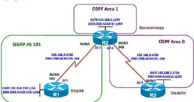
Una empresa de confecciones posee tres sucursales
distribuidas en las ciudades de Bogotá, Medellín y Bucaramanga,
en donde el estudiante será el administrador de la red, el
cual deberá configurar e interconectar entre sí cada uno de los
dispositivos que forman parte del escenario, acorde con los
lineamientos establecidos para el direccionamiento IP, protocolos
de enrutamiento y demás aspectos que forman parte de la
topología de red.
1.1 Topología de red.
Ilustración 1: Topología de red escenario 1.
Parte 1: Configuración del escenario propuesto.
11
B. Ajustar el ancho de banda a 128 kbps sobre cada uno de los enlaces
seriales ubicados en R1, R2, y R3 y ajustar la velocidad de reloj de las
conexiones de DCE según sea apropiado.
R1
Router>enable
Router#config t
Enter configuration commands, one per line. End with CNTL/Z.
Router(config)#hostname R1
R1(config)#int S0/0/0
R1(config-if)#ip address 192.168.9.1 255.255.255.252
R1(config-if)#ipv6 address 2001:DB8:ACAD:90::1/64
R1(config-if)#bandwidth 128
R1(config-if)#clock rate 128000
R1(config-if)#no shutdown
%LINK-5-CHANGED: Interface Serial0/0/0, changed state to down
R1(config-if)#exit
R1(config)#int fa 0/0
R1(config-if)#ip address 192.168.110.1 255.255.255.0
R1(config-if)#ipv6 address 2001:DB8:ACAD:10::1/64
R1(config-if)#no shutdown
R1(config-if)#
%LINK-5-CHANGED: Interface FastEthernet0/0, changed state to up
exit
R1(config)#
R1#
%SYS-5-CONFIG_I: Configured from console by console R2
Router>enable
Router#config t
Enter configuration commands, one per line. End with CNTL/Z.
Router(config)#hostname R2
R2(config)#int s0/0/0
R2(config-if)#ip address 192.168.9.2 255.255.255.252
R2(config-if)#ipv6 address 2001:DB8:ACAD:90::2/64
R2(config-if)#bandwidth 128
R2(config-if)#no shutdown
12
%LINK-5-CHANGED: Interface Serial0/0/0, changed state to up
%LINEPROTO-5-UPDOWN: Line protocol on Interface Serial0/0/0, changed
state to up
R2(config-if)#exit
R2(config)#int fa 0/0
R2(config-if)#ip address 192.168.2.1 255.255.255.0
R2(config-if)#ipv6 address 2001:DB8:ACAD:B::1/64
R2(config-if)#no shutdown
R2(config-if)#
%LINK-5-CHANGED: Interface FastEthernet0/0, changed state to up
R2(config-if)#exit
R2(config)#int s0/0/1
R2(config-if)#ip address 192.168.9.5 255.255.255.252
R2(config-if)#ipv6 address 2001:DB8:ACAD:91::1/64
R2(config-if)#bandwidth 128
R2(config-if)#clock rate 128000
R2(config-if)#no shutdown
%LINK-5-CHANGED: Interface Serial0/0/1, changed state to down
R2(config-if)#
R2#
%SYS-5-CONFIG_I: Configured from console by console
R3
Router>enable
Router#config t
Enter configuration commands, one per line. End with CNTL/Z.
Router(config)#hostname R3
R3(config)#int s0/0/1
R3(config-if)#ip address 192.168.9.6 255.255.255.252
R3(config-if)#ipv6 address 2001:DB8:ACAD:91::2/64
R3(config-if)#bandwidth 128
R3(config-if)#no shutdown
R3(config-if)#
%LINK-5-CHANGED: Interface Serial0/0/1, changed state to up
13
R3(config-if)#exit
R3(config)#int fa o/0
^
% Invalid input detected at '^' marker.
R3(config)#int fa 0/0
R3(config-if)#ip address 192.168.3.1 255.255.255.0
R3(config-if)#ipv6 address 2001:DB8:ACAD:C::1/64
R3(config-if)#no shutdown
R3(config-if)#
%LINK-5-CHANGED: Interface FastEthernet0/0, changed state to up
exit
R3(config)#
C. En R2 y R3 configurar las familias de direcciones OSPFv3 para IPv4 e
IPv6. Utilice el identificador de enrutamiento 2.2.2.2 en R2 y 3.3.3.3 en
R3 para ambas familias de direcciones.
Ospf en 2 y 3
R2>
R2>enable
R2#config t
Enter configuration commands, one per line. End with CNTL/Z.
R2(config)#ipv6 unicast-routing
R2(config)#router ospfv3 1
^
% Invalid input detected at '^' marker.
R2(config)#router ospf 1
R2(config-router)#router-id 2.2.2.2
R2(config-router)#address-family ipv6 unicast
^
% Invalid input detected at '^' marker.
R2(config-router)#
R2(config-router)#
R2(config-router)#
R2#
%SYS-5-CONFIG_I: Configured from console by console
R3>enable
R3#config t
Enter configuration commands, one per line. End with CNTL/Z.
R3(config)#ipv6 unicast-routing
14
R3(config-router)#router-id 3.3.3.3
R3(config-router)#
R3(config-router)#
R3#
%SYS-5-CONFIG_I: Configured from console by console
D. En R2, configurar la interfaz F0/0 en el área 1 de OSPF y la conexión
serial entre R2 y R3 en OSPF área 0.
R2(config)#router ospf 1
R2(config-router)#network 192.168.2.0 0.0.0.255 area 1
R2(config-router)#network 192.168.9.4 0.0.0.3 area 0
R2(config-router)#ipv6 unicast-routing
R2(config)#ipv6 router ospf 1
R2(config-rtr)#router-id 2.2.2.2
R2(config-rtr)#exit
R2(config)#int fa 0/0
R2(config-if)#ipv6 ospf 1 area 1
R2(config-if)#no shutdown
R2(config-if)#exit
R2(config)#int s0/0/1
R2(config-if)#ipv6 ospf 1 area 0
R2(config-if)#no shutdown
R2(config-if)#
E. En R3, configurar la interfaz F0/0 y la conexión serial entre R2 y R3 en
OSPF área 0.
R3>
R3>enable
R3#config t
Enter configuration commands, one per line. End with CNTL/Z.
R3(config)#router ospf 1
R3(config-router)#network 192.168.3.0 0.0.0.255 area 0
R3(config-router)#network 192.168.9.4 0.0.0.3 area 0
R3(config-router)#ipv6
01:06:32: %OSPF-5-ADJCHG: Process 1, Nbr 2.2.2.2 on Serial0/0/1 from
LOADING to FULL, Loading
R3(config-router)#ipv6 unicast-routing
R3(config)#ipv6 router ospf 1
15
R3(config-rtr)#exit
R3(config)#int fa 0/0
R3(config-if)#ipv6 ospf 1 area 1
R3(config-if)#no shutdown
R3(config-if)#exit
R3(config)#int s0/0/1
R3(config-if)#ipv6 ospf 1 area 0
R3(config-if)#no shutdo
01:09:05: %OSPFv3-5-ADJCHG: Process 1, Nbr 2.2.2.2 on Serial0/0/1 from
LOADING to FULL, Load
R3(config-if)#no shutdown
R3(config-if)#
R3#
%SYS-5-CONFIG_I: Configured from console by console
F. Configurar el área 1 como un área totalmente Stubby.
R2#enable
R2#config t
Enter configuration commands, one per line. End with CNTL/Z.
R2(config)#int fa 0/0
R2(config-if)#router ospf 1
R2(config-router)#area 1 stub
R2(config-router)#exit
R2(config)#
R2#
%SYS-5-CONFIG_I: Configured from console by console
G. Propagar rutas por defecto de IPv4 y IPv6 en R3 al interior del dominio
OSPFv3. Nota: Es importante tener en cuenta que una ruta por defecto
es diferente a la definición de rutas estáticas.
R3(config)#router ospf 1
R3(config-router)#log-adjacency-changes
R3(config-router)#
R3(config-router)#exit
R3(config)#ipv6 router ospf 1
R3(config-rtr)#log adjacency-changes
16
^
% Invalid input detected at '^' marker.
R3(config)#ipv6 router ospf 1
R3(config-rtr)#log-adjacency-changes
R3(config-rtr)#exit
R3(config)#
R3#
%SYS-5-CONFIG_I: Configured from console by console
H. Realizar la configuración del protocolo EIGRP para IPv4 como IPv6.
Configurar la interfaz F0/0 de R1 y la conexión entre R1 y R2 para
EIGRP con el sistema autónomo 101. Asegúrese de que el resumen
automático está desactivado.
R1#
R1#enable
R1#config t
Enter configuration commands, one per line. End with CNTL/Z.
R1(config)#ipv6 unicast-routing
R1(config)#router eigrp 101
R1(config-router)#network 192.168.110.0
R1(config-router)#network 192.168.9.0
R1(config-router)#no auto-summary
R1(config-router)#exit
R1(config)#int fa 0/0
R1(config-if)#ipv6 eigrp 101
R1(config-if)#exit
R1(config)#int s0/0/0
R1(config-if)#ipv6 eigrp 101
R1(config-if)#exit
R1(config)#
R2>enable
R2#config t
Enter configuration commands, one per line. End with CNTL/Z.
R2(config)#router eigrp 101
R2(config-router)#network 192.168.2.0
R2(config-router)#network 192.168.9.0
R2(config-router)#
17
R2(config-router)#no auto-summary
R2(config-router)#
%DUAL-5-NBRCHANGE: IP-EIGRP 101: Neighbor 192.168.9.1 (Serial0/0/0)
resync: summary configured
R2(config-router)#
I. Configurar las interfaces pasivas para EIGRP según sea apropiado.
R1#config t
Enter configuration commands, one per line. End with CNTL/Z.
R1(config)#router eigrp 101
R1(config-router)#passive-interface s0/0/0
R1(config-router)#passive-interface fa0/0
R1(config-router)#
R1(config-router)#exit
R1(config)#end
J. En R2, configurar la redistribución mutua entre OSPF y EIGRP para
IPv4 e IPv6. Asignar métricas apropiadas cuando sea necesario.
R2#
R2#config t
Enter configuration commands, one per line. End with CNTL/Z.
R2(config)#router eigrp 101
R2(config-router)#redistribute ospf 1 metric?
metric
R2(config-router)#router eigrp 101?
% Unrecognized command
R2(config-router)#redistribute ospf 1 metric ?
<1-4294967295> Bandwidth metric in Kbits per second
R2(config-router)#redistribute ospf 1 metric 155 ?
<0-4294967295> EIGRP delay metric, in 10 microsecond units
R2(config-router)#redistribute ospf 1 metric 155 300?
<0-4294967295>
R2(config-router)#redistribute ospf 1 metric 155 300?
<0-4294967295>
18
<0-255>
R2(config-router)#redistribute ospf 1 metric 155 300 110 1?
<1-255>
R2(config-router)#redistribute ospf 1 metric 155 300 110 1 250?
<1-65535>
R2(config-router)#redistribute ospf 1 metric 155 300 110 1 250
R2(config-router)#
K. En R2, de hacer publicidad de la ruta 192.168.3.0/24 a R1 mediante una
lista de distribución y ACL.
R2#
R2#config t
Enter configuration commands, one per line. End with CNTL/Z.
R2(config)#access-list 1 denny 192.168.3.0 0.0.0.255
^
% Invalid input detected at '^' marker.
R2(config)#access-list 1 deny 192.168.3.0 0.0.0.255
R2(config)#access-list 1 permit any
R2(config)#
R2(config)#
R2#show access-list
Standard IP access list 1
10 deny 192.168.3.0 0.0.0.255
20 permit any
R2#
R2#
Parte 2: Verificar conectividad de red y control de la trayectoria.
A. Registrar las tablas de enrutamiento en cada uno de los routers, acorde
con los parámetros de configuración establecidos en el escenario
propuesto.
19
Codes: C - connected, S - static, I - IGRP, R - RIP, M - mobile, B - BGP
D - EIGRP, EX - EIGRP external, O - OSPF, IA - OSPF inter area
N1 - OSPF NSSA external type 1, N2 - OSPF NSSA external type 2
E1 - OSPF external type 1, E2 - OSPF external type 2, E - EGP
i - IS-IS, L1 - IS-IS level-1, L2 - IS-IS level-2, ia - IS-IS inter area
* - candidate default, U - per-user static route, o - ODR
P - periodic downloaded static route
Gateway of last resort is not set
192.168.9.0/30 is subnetted, 1 subnets
C 192.168.9.0 is directly connected, Serial0/0/0
R1#show ip route
Codes: C - connected, S - static, I - IGRP, R - RIP, M - mobile, B - BGP
D - EIGRP, EX - EIGRP external, O - OSPF, IA - OSPF inter area
N1 - OSPF NSSA external type 1, N2 - OSPF NSSA external type 2
E1 - OSPF external type 1, E2 - OSPF external type 2, E - EGP
i - IS-IS, L1 - IS-IS level-1, L2 - IS-IS level-2, ia - IS-IS inter area
* - candidate default, U - per-user static route, o - ODR
P - periodic downloaded static route
Gateway of last resort is not set
192.168.9.0/30 is subnetted, 1 subnets
C 192.168.9.0 is directly connected, Serial0/0/0
R1#
R1
20
R2
Ilustración 3: Tabla enrutamiento R2
R3
Ilustración 4: Tabla enrutamiento R3.
21
Ping 1 a 2
Ilustración 5: Verificación comunicación Ping 1 a 2.
Ping 2 a 1
Ilustración 6: Verificación comunicación Ping 2 a 1.
Ping 2 a 3
22
Ping 3 a 2
Ilustración 8: Verificación comunicación Ping 3 a 2.
C. Verificar que las rutas filtradas no están presentes en las tablas de
enrutamiento de los routers correctas.
R1
Ilustración 9: Rutas filtradas R1
23
R2
Ilustración 10: Rutas Filtradas R2.
R3
24
ESCENARIO 2.
Descripción del escenario propuestos para la prueba de habilidades.
2. Escenario 2 propuesto para la prueba de habilidades.
Una empresa de comunicaciones presenta una estructura Core acorde
a la topología de red, en donde el estudiante será el administrador de
la red, el cual deberá configurar e interconectar entre sí cada uno de
los dispositivos que forman parte del escenario, acorde con los
lineamientos establecidos para el direccionamiento IP, etherchannels,
VLANs y demás aspectos que forman parte del escenario propuesto.
2.1. Topología de red.
Ilustración 12: Topología de red escenario 2.
Parte 1: Configuración de la red de acuerdo con las especificaciones.
A.
Apagar todas las interfaces en cada switch.
25
Switch> Switch>enable Switch#config t
Enter configuration commands, one per line. End with CNTL/Z. Switch(config)#hostname DSL1
DSL1(config)#int ran f0/1-24 DSL1(config-if-range)#shutdown DSL1(config-if-range)#exit DSL1(config)#
DSL1#
%SYS-5-CONFIG_I: Configured from console by console
Switch>enable Switch#config t
Enter configuration commands, one per line. End with CNTL/Z. Switch(config)#hostname DSL2
DSL2(config)#int ran f0/1-24 DSL2(config-if-range)#shutdown DSL2(config-if-range)#exit DSL2(config)#
Switch>enable Switch#config t
Enter configuration commands, one per line. End with CNTL/Z. Switch(config)#hostname ALS1
ALS1(config)#int ran f0/1-24 ALS1(config-if-range)#shutdown ALS1(config-if-range)#exit ALS1(config)#
Switch>enable Switch#config t
Enter configuration commands, one per line. End with CNTL/Z. Switch(config)#hostname ALS2
ALS2(config)#int ran f0/1-24 ALS2(config-if-range)#shutdown ALS2(config-if-range)#exit ALS2(config)#
26
1. La conexión entre DLS1 y DLS2 será un EtherChannel
capa-3 utilizando LACP. Para DLS1 se utilizará la dirección
IP 10.12.12.1/30 y para DLS2 utilizará 10.12.12.2/30.
DSL1(config)#int vlan 800
DSL1(config-if)#ip address 10.12.12.1 255.255.255.252 DSL1(config-if)#int ran f0/11-12
DSL1(config-if-range)#channel-protocol lacp
DSL1(config-if-range)#channel-group 12 mode active DSL1(config-if-range)#
Creating a port-channel interface Port-channel 2
DSL1(config-if-range)#no shutdown
%LINK-5-CHANGED: Interface FastEthernet0/11, changed state to down
%LINK-5-CHANGED: Interface FastEthernet0/12, changed state to down DSL1(config-if-range)#exit
DSL1(config)#
DSL2(config)#int vlan 800
DSL2(config-if)#ip address 10.12.12.2 255.255.255.252 DSL2(config-if)#int ran f0/11-12
DSL2(config-if-range)#channel-protocol lacp
DSL2(config-if-range)#channel-group 12 mode active DSL2(config-if-range)#
Creating a port-channel interface Port-channel 2
DSL2(config-if-range)#no shutdown
DSL2(config-if-range)#
%LINK-5-CHANGED: Interface FastEthernet0/11, changed state to up
%LINEPROTO-5-UPDOWN: Line protocol on Interface FastEthernet0/11, changed state to up
%LINK-5-CHANGED: Interface FastEthernet0/12, changed state to up
%LINEPROTO-5-UPDOWN: Line protocol on Interface FastEthernet0/12, changed state to up
%LINK-5-CHANGED: Interface Port-channel2, changed state to up
27
DSL2(config-if-range)#exit DSL2(config)#
2. Los Port-channels en las interfaces Fa0/7 y Fa0/8 utilizarán
LACP.
DSL1(config)#int ran f0/7-8
DSL1(config-if-range)#channel-protocol lacp
DSL1(config-if-range)#channel-group 1 mode active DSL1(config-if-range)#no shutdown
%LINK-5-CHANGED: Interface FastEthernet0/7, changed state to down
%LINK-5-CHANGED: Interface FastEthernet0/8, changed state to down DSL1(config-if-range)#exit
DSL1(config)#
DSL2(config)#int ran f0/7-8
DSL2(config-if-range)#channel-protocol lacp
DSL2(config-if-range)#channel-group 2 mode active DSL2(config-if-range)#no shutdown
%LINK-5-CHANGED: Interface FastEthernet0/7, changed state to down
%LINK-5-CHANGED: Interface FastEthernet0/8, changed state to down DSL2(config-if-range)#exit
DSL2(config)#
ALS1(config)#int ran f0/7-8
ALS1(config-if-range)#channel-protocol lacp
ALS1(config-if-range)#channel-group 1 mode active ALS1(config-if-range)#
Creating a port-channel interface Port-channel 2
ALS1(config-if-range)#no shutdown
ALS1(config-if-range)#
%LINK-5-CHANGED: Interface FastEthernet0/7, changed state to up
28
%LINK-5-CHANGED: Interface FastEthernet0/8, changed state to up
%LINEPROTO-5-UPDOWN: Line protocol on Interface FastEthernet0/8, changed state to up
ALS1(config-if-range)#exit
ALS2(config)#int ran f0/7-8
ALS2(config-if-range)#channel-protocol lacp
ALS2(config-if-range)#channel-group 2 mode active ALS2(config-if-range)#
Creating a port-channel interface Port-channel 2
ALS2(config-if-range)#no shutdown
%LINK-5-CHANGED: Interface FastEthernet0/7, changed state to down
%LINK-5-CHANGED: Interface FastEthernet0/8, changed state to down ALS2(config-if-range)#exit
ALS2(config)#
3. Los Port-channels en las interfaces F0/9 y fa0/10 utilizará
PAgP.
DSL1(config)#int ran f0/9-10
DSL1(config-if-range)#channel-protocol pagp
DSL1(config-if-range)#channel-group 4 mode desirable DSL1(config-if-range)#no shutdown
%LINK-5-CHANGED: Interface FastEthernet0/9, changed state to down
%LINK-5-CHANGED: Interface FastEthernet0/10, changed state to down DSL1(config-if-range)#exit
DSL1(config)#
DSL2(config)#int ran f0/9-10
DSL2(config-if-range)#channel-protocol pagp
DSL2(config-if-range)#channel-group 3 mode desirable DSL2(config-if-range)#no shutdown
%LINK-5-CHANGED: Interface FastEthernet0/9, changed state to down
%LINK-5-CHANGED: Interface FastEthernet0/10, changed state to down DSL2(config-if-range)#exit
DSL2(config)#
ALS1(config)#int ran f0/9-10
29
ALS1(config-if-range)#channel-group 3 mode desirable ALS1(config-if-range)#no shutdown
ALS1(config-if-range)#
%LINK-5-CHANGED: Interface FastEthernet0/9, changed state to up
%LINEPROTO-5-UPDOWN: Line protocol on Interface FastEthernet0/9, changed state to up
%LINK-5-CHANGED: Interface FastEthernet0/10, changed state to up
%LINEPROTO-5-UPDOWN: Line protocol on Interface FastEthernet0/10, changed state to up
ALS1(config-if-range)#exit ALS1(config)#
ALS2(config)#int ran f0/9-10
ALS2(config-if-range)#channel-protocol pagp
ALS2(config-if-range)#channel-group 4 mode desirable ALS2(config-if-range)#no shutdown
ALS2(config-if-range)#
%LINK-5-CHANGED: Interface FastEthernet0/9, changed state to up
%LINEPROTO-5-UPDOWN: Line protocol on Interface FastEthernet0/9, changed state to up
%LINK-5-CHANGED: Interface FastEthernet0/10, changed state to up
%LINEPROTO-5-UPDOWN: Line protocol on Interface FastEthernet0/10, changed state to up
ALS2(config-if-range)#exit ALS2(config)#
4. Todos los puertos troncales serán asignados a la VLAN 800
como la VLAN nativa.
DSL1(config)#int ran f0/7-12
DSL1(config-if-range)#switchport trunk encap dot1q DSL1(config-if-range)#switchport trunk native vlan 800 DSL1(config-if-range)#switchport mode trunk
DSL1(config-if-range)#switchport nonegotiate DSL1(config-if-range)#no shutdown
30
DSL1(config)#
DSL2>enable DSL2#config t
Enter configuration commands, one per line. End with CNTL/Z. DSL2(config)#int ran f0/7-12
DSL2(config-if-range)#switcport trunk en
%CDP-4-NATIVE_VLAN_MISMATCH: Native VLAN mismatch discovered on FastEthernet0/11 (1), with DSL1 FastEthernet0/11 (800).
%CDP-4-NATIVE_VLAN_MISMATCH: Native VLAN mismatch discovered on FastEthernet0/12 (1), with DSL1 FastEthernet0/11 (800).
%CDP-4-NATIVE_VLAN_MISMATCH: Native VLAN mismatch discovered on FastEthernet0/11 (1), with DSL1 FastEthernet0/12 (800).
%CDP-4-NATIVE_VLAN_MISMATCH: Native VLAN mismatch discovered on FastEthernet0/12 (1), with DSL1 FastEthernet0/12 (800).
DSL2(config-if-range)#switchport trunk encap dot1q DSL2(config-if-range)#switchport trunk native vlan 800 DSL2(config-if-range)#switchport mode trunk
DSL2(config-if-range)#switchport nonegotiate DSL2(config-if-range)#no shutdown
DSL2(config-if-range)#exit DSL2(config)#
ALS1#config t
Enter configuration commands, one per line. End with CNTL/Z. ALS1(config)#int ran f0/7-10
ALS1(config-if-range)#switchport trunk encap dot1q ALS1(config-if-range)#switchport trunk native vlan 800 ALS1(config-if-range)#switchport mode trunk
ALS1(config-if-range)#switchport nonegotiate ALS1(config-if-range)#no shutdown
ALS1(config-if-range)#exit ALS1(config)#
ALS2(config)#int ran f0/7-10
ALS2(config-if-range)#switchport trunk encap dot1q ALS2(config-if-range)#switchport trunk native vlan 800 ALS2(config-if-range)#switchport mode trunk
ALS2(config-if-range)#switchport nonegotiate ALS2(config-if-range)#no shutdown
31
D. Configurar DLS1, ALS1, y ALS2 para utilizar VTP versión 3.
1. Configurar DLS1, ALS1, y ALS2 para utilizar VTP versión 3.
DSL1(config)#vtp mode server Device mode already VTP SERVER. DSL1(config)#vtp domain UNAD
Changing VTP domain name from NULL to UNAD DSL1(config)#vtp password cisco123
Setting device VLAN database password to cisco123 DSL1(config)#exit
DSL1#
ALS1(config)#vtp mode server Device mode already VTP SERVER. ALS1(config)#vtp domain UNAD
Changing VTP domain name from NULL to UNAD ALS1(config)#vtp password cisco123
Setting device VLAN database password to cisco123 ALS1(config)#exit
ALS1#
ALS2(config)#vtp mode server Device mode already VTP SERVER. ALS2(config)#vtp domain UNAD
Changing VTP domain name from NULL to UNAD ALS2(config)#vtp password cisco123
Setting device VLAN database password to cisco123 ALS2(config)#exit
ALS2#
2.
Configurar DLS1 como servidor principal para las VLAN.
DSL1(config)#vtp version 2
DSL1(config)#vtp mode server mst ^
% Invalid input detected at '^' marker. DSL1(config)#end
DSL1#
3. Configurar ALS1 y ALS2 como clientes VTP.
ALS1(config)#vtp mode clientSetting device to VTP CLIENT mode. ALS1(config)#vtp domain UNAD Domain name already set to UNAD. ALS1(config)#vtp password cisco123
32
ALS1(config)#exit
ALS2(config)#vtp mode client Setting device to VTP CLIENT mode. ALS2(config)#vtp domain UNAD Domain name already set to UNAD. ALS2(config)#vtp password cisco123
Setting device VLAN database password to cisco123 ALS2(config)#exit
E. Configurar en el servidor principal las siguientes VLAN:
Tabla 1:Configurar las VLAN.
33 DSL1(config-vlan)#exit DSL1(config)#vlan 3456 DSL1(config-vlan)#name ADMINISTRACION DSL1(config-vlan)#exit DSL1(config)#
Se crearon todas las VLAN en DSL1 desde el modo VTP transparent
F. En DLS1, suspender la VLAN 434.
DSL1(config)#vlan 434 DSL1(config-vlan)#shutdown ^
% Invalid input detected at '^' marker. DSL1(config-vlan)#state ?
% Unrecognized command DSL1(config-vlan)#state suspend ^
% Invalid input detected at '^' marker. DSL1(config-vlan)#name estacionamiento DSL1(config-vlan)#shutdown
^
% Invalid input detected at '^' marker. DSL1(config-vlan)#state suspend ^
% Invalid input detected at '^' marker. DSL1(config-vlan)#
En PACKET TRACER las VLAN no se pueden suspender global ni
localmente con los comandos stated-suspend y shutdown porque no se
reconocen los comandos.
G. Configurar DLS2 en modo VTP transparente VTP utilizando VTP
versión 2, y configurar en DLS2 las mismas VLAN que en DLS1.
DSL2(config)#vtp version 2
DSL2(config)#vtp mode transparent
Setting device to VTP TRANSPARENT mode. DSL2(config)#vlan 800
DSL2(config-vlan)#
%LINK-5-CHANGED: Interface Vlan800, changed state to up
%LINEPROTO-5-UPDOWN: Line protocol on Interface Vlan800, changed state to up
34 DSL2(config)#vlan 12 DSL2(config-vlan)#name EJECUTIVOS DSL2(config-vlan)#exit DSL2(config)#vlan 234 DSL2(config-vlan)#name HUESPEDES DSL2(config-vlan)#exit DSL2(config)#vlan 123 DSL2(config-vlan)#name MANTENIMIENTO DSL2(config-vlan)#exit DSL2(config)#vlan 1111 DSL2(config-vlan)#name VIDEONET DSL2(config-vlan)#exit DSL2(config-vlan)#vlan 1010 DSL2(config-vlan)#name VOZ DSL2(config-vlan)#exit DSL2(config)#vlan 3456 DSL2(config-vlan)#name ADMINISTRACION DSL2(config-vlan)#exit
H. Suspender VLAN 434 en DLS2.
En PACKET TRACER las VLAN no se pueden suspender global ni
localmente con los comandos stated suspend y shut down por que no se
reconocen los comandos.
I. En DLS2, crear VLAN 567 con el nombre de CONTABILIDAD. La
VLAN de CONTABILIDAD no podrá estar disponible en cualquier otro
Switch de la red.
DSL2(config)#vlan 567
DSL2(config-vlan)#name CONTABILIDAD DSL2(config-vlan)#private-vlan isolated ^
% Invalid input detected at '^' marker. DSL2(config-vlan)#exit
DSL2(config)#vlan 567
DSL2(config-vlan)#private-vlan isolated ^
% Invalid input detected at '^' marker.
J. Configurar DLS1 como Spanning tree root para las VLAN 1, 12, 434,
800, 1010, 1111 y 3456 y como raíz secundaria para las VLAN 123 y
234.
35
DSL1(config)#spanning-tree vlan 800 root primary DSL1(config)#spanning-tree vlan 1010 root primary DSL1(config)#spanning-tree vlan 1111 root primary DSL1(config)#spanning-tree vlan 3456 root primary DSL1(config)#
DSL1(config)#
DSL1(config)#spanning-tree vlan 123 root secondary DSL1(config)#spanning-tree vlan 234 root secondary DSL1(config)#
DSL1(config)#
K. Configurar DLS2 como Spanning tree root para las VLAN 123 y 234 y
como una raíz secundaria para las VLAN 12, 434, 800, 1010, 1111 y
3456.
DSL2(config)#spanning-tree vlan 123 root primary DSL2(config)#spanning-tree vlan 234 root primary DSL2(config)#
DSL2(config)#
DSL2(config)#spanning-tree vlan 12 root secondary DSL2(config)#spanning-tree vlan 434 root secondary DSL2(config)#spanning-tree vlan 800 root secondary DSL2(config)#spanning-tree vlan 1010 root secondary DSL2(config)#spanning-tree vlan 1111 root secondary DSL2(config)#spanning-tree vlan 3456 root secondary DSL2(config)#
DSL2(config)#
L. Configurar todos los puertos como troncales de tal forma que
solamente las VLAN que se han creado se les permitirá circular a
través de éstos puertos.
DSL1(config)#int ran f0/7-12
DSL1(config-if-range)#switchport trunk encapsulation dot1q DSL1(config-if-range)#switchport trunk native vlan 800 DSL1(config-if-range)#switchport mode trunk
DSL1(config-if-range)# DSL1(config-if-range)#exit DSL1(config)#
DSL2(config)#int ran f0/7-12
DSL2(config-if-range)#switchport trunk encapsulation dot1q DSL2(config-if-range)#switchport trunk native vlan 800 DSL2(config-if-range)#switchport mode trunk
DSL2(config-if-range)#exit DSL2(config)#
36
ALS1(config-if-range)#switchport trunk encapsulation dot1q ^
% Invalid input detected at '^' marker.
ALS1(config-if-range)#switchport trunk native vlan 800 ALS1(config-if-range)#switchport mode trunk
ALS1(config-if-range)#exit ALS1(config)#
ALS2(config)#int ran f0/7-12
ALS2(config-if-range)#switchport trunk encapsulation dot1q ^
% Invalid input detected at '^' marker.
ALS2(config-if-range)#switchport trunk native vlan 800 ALS2(config-if-range)#switchport mode trunk
ALS2(config-if-range)# ALS2(config-if-range)#exit
DSL1(config)#int ran f0/7-12
DSL1(config-if-range)#switchport mode trunk DSL1(config-if-range)#
DSL1(config-if-range)#switchport trunk native vlan 800 DSL1(config-if-range)#switchport trunk native vlan 12 DSL1(config-if-range)#switchport trunk native vlan 234 DSL1(config-if-range)#switchport trunk native vlan 1111 DSL1(config-if-range)#switchport trunk native vlan 434 DSL1(config-if-range)#switchport trunk native vlan 123 DSL1(config-if-range)#switchport trunk native vlan 1010 DSL1(config-if-range)#switchport trunk native vlan 3456 DSL1(config-if-range)#switchport nonegotiate
DSL2(config)#int ran f0/7-12
DSL2(config-if-range)#switchport mode trunk DSL2(config-if-range)#
DSL2(config-if-range)#switchport trunk native vlan 800 DSL2(config-if-range)#switchport trunk native vlan 12 DSL2(config-if-range)#switchport trunk native vlan 234 DSL2(config-if-range)#switchport trunk native vlan 1111 DSL2(config-if-range)#switchport trunk native vlan 434 DSL2(config-if-range)#switchport trunk native vlan 123 DSL2(config-if-range)#switchport trunk native vlan 1010 DSL2(config-if-range)#switchport trunk native vlan 3456 DSL2(config-if-range)#switchport nonegotiate
ALS1(config)#int ran f0/7-12
ALS1(config-if-range)#switchport mode trunk ALS1(config-if-range)#
37
ALS1(config-if-range)#switchport trunk native vlan 1111 ALS1(config-if-range)#switchport trunk native vlan 434 ALS1(config-if-range)#switchport trunk native vlan 123 ALS1(config-if-range)#switchport trunk native vlan 1010 ALS1(config-if-range)#switchport trunk native vlan 3456 ALS1(config-if-range)#switchport nonegotiate
ALS2(config)#int ran f0/7-12
ALS2(config-if-range)#switchport mode trunk ALS2(config-if-range)#
ALS2(config-if-range)#switchport trunk native vlan 800 ALS2(config-if-range)#switchport trunk native vlan 12 ALS2(config-if-range)#switchport trunk native vlan 234 ALS2(config-if-range)#switchport trunk native vlan 1111 ALS2(config-if-range)#switchport trunk native vlan 434 ALS2(config-if-range)#switchport trunk native vlan 123 ALS2(config-if-range)#switchport trunk native vlan 1010 ALS2(config-if-range)#switchport trunk native vlan 3456 ALS2 (config-if-range)#switchport nonegotiate
ALS2(config)#
M. Configurar las siguientes interfaces como puertos de acceso,
asignados a las VLAN de la siguiente manera:
Tabla 2: Puertos acceso VLAN.
DSL1(config-if-range)#switchport nonegotiate DSL1(config-if-range)#exit
DSL1(config)#int f0/6
DSL1(config-if)#switchport access vlan 3456 DSL1(config-if)#no shutdown
DSL1(config-if)#int f0/15
DSL1(config-if)#switchport access vlan 1111 DSL1(config-if)#no shutdown
DSL1(config-if)#exit DSL1(config)#
DSL2(config)#int f0/6
38
DSL2(config-if)#switchport access vlan 101 % Access VLAN does not exist. Creating vlan 101 DSL2(config-if)#switchport access vlan 1010 DSL2(config-if)#no shutdown
DSL2(config-if)#exit DSL2(config-if)#int f0/15
DSL2(config-if)#switchport access vlan 1111 DSL2(config-if)#no shutdown
DSL2(config-if)#exit
DSL2(config)#int ran f0/16-18
DSL2(config-if-range)#switchport access vlan 567 DSL2(config-if-range)#no shutdown
DSL2(config-if-range)#exit DSL2(config)#
ALS1(config)#int f0/6
ALS1(config-if)#switchport access vlan 123 ALS1(config-if)#switchport access vlan 1010 ALS1(config-if)#no shutdown
ALS1(config-if)#exit ALS1(config)#int f0/15
ALS1(config-if)#switchport access vlan 1111 ALS1(config-if)#no shutdown
ALS1(config-if)#exit ALS1(config)#
ALS2(config)#int f0/6
ALS2(config-if)#switchport access vlan 234 ALS2(config-if)#no shutdown
ALS2(config-if)#exit ALS2(config)#int f0/15
ALS2(config-if)#switchport access vlan 1111 ALS2(config-if)#no shutdown
39
Parte 2: de red de prueba y las opciones configuradas.
A. Verificar la existencia de las VLAN correctas en todos los switches y la
asignación de puertos troncales y de acceso.
A
40
Ilustración 14: Vlans y enlaces troncales DSL1 (2)
41
Ilustración 16: Vlans y enlaces troncales DSL2 (2)
42
Ilustración 18: Vlans y enlaces troncales ALS1(2)
43
Ilustración 20: Vlans y enlaces troncales ALS2(2)
B. Verificar que el EtherChannel entre DLS1 y ALS1 está configurado
correctamente
44
Ilustración 22: Show etherchannel ALS1
C. Verificar la configuración de Spanning tree entre DLS1 o DLS2 para
cada VLAN.
45
Ilustración 24: DSL1-VLAN0012
46
Ilustración 26: DSL1-VLAN0234
47
Ilustración 28: DSL1-VLAN0800
48
Ilustración 30: DSL2-VLAN0001
49
Ilustración 32: DSL2-VLAN0123
50
Ilustración 34: DSL2-VLAN0434
51
Ilustración 36: DSL2-VLAN0800
52
CONCLUSIONES
De acuerdo con la implementación de los protocolos EIGRP, OSPF, en el
primer escenario se pudo constatar que brindan una solución a los ejercicios
planteados en las pruebas de habilidades.
De igual manera, se evidenció que las listas de acceso permiten realizar
configuraciones de seguridad para evitar accesos no autorizados y controlar
el tráfico dentro de la red.
En cuanto al segundo escenario, la herramienta de simulación packet tracer
crea ambientes muy similares a la realidad y permite una simulación en tiempo
real.
53