UNIVERSIDAD NACIONAL ABIERTA Y A DISTANCIA - UNAD ESCUELA DE CIENCIAS BÁSICAS, TECNOLOGÍA E INGENIERÍA ECBTI
DIPLOMADO DE PROFUNDIZACIÓN CISCO CCNP BOGOTA COLOMBIA
2019
EVALUACIÓN FINAL
PRUEBA DE HABILIDADES PRÁCTICAS CCNP
UNIVERSIDAD NACIONAL ABIERTA Y A DISTANCIA - UNAD ESCUELA DE CIENCIAS BÁSICAS, TECNOLOGÍA E INGENIERÍA ECBTI
DIPLOMADO DE PROFUNDIZACIÓN CISCO CCNP BOGOTA COLOMBIA
2019
EVALUACIÓN PRUEBA DE HABILIDADES PRÁCTICAS CCNP
SÁNCHEZ DIAZ PAULA DANIELA
Diplomado de Profundización CISCO
NOTA DE ACEPTACION
Presidente del jurado
Jurado
Jurado
DEDICATORIA
AGRADECIMIENTOS
A mis padres quienes son mi motor y mi mayor inspiración, que, a través de su amor, paciencia, buenos valores, ayudan a trazar mi camino.
TABLA DE CONTENIDO
LISTA DE TABLAS ... 7
LISTA DE FIGURAS ... 8
GLOSARIO ... 9
RESUMEN ... 10
ABSTRACT ... 10
INTRODUCCIÓN ... 11
1. OBJETIVOS ... 12
1.1. Objetivo General ...12
1.2. Objetivos Específicos ...12
2. DESARROLLO DEL TRABAJO ... 13
2.1. Escenario 1 ...13
2.1.1. Planteamiento del problema ...13
2.1.2. Solución escenario 1 ...15
2.2. Escenario 2 ...26
2.2.1. Planteamiento del problema ...26
2.2.2. Solución escenario 2 ...29
CONCLUSIONES ... 47
LISTA DE TABLAS
LISTA DE FIGURAS
Figura 1.Escenario 1 ... 13
Figura 2. Configuración interfaces. ... 20
Figura 3.Conectividad de red ... 24
Figura 4. Pin R2 A R3 Y R1 ... 24
Figura 5. Ping R1 a R2 y R3. ... 25
Figura 6. Escenario 2 ... 26
Figura 7. Solución escenario 2 ... 31
Figura 8. Configuración puertos. ... 38
Figura 9. Configuración DLS 1 ... 40
Figura 10. Host A ... 43
Figura 11. Host B ... 43
Figura 12. Host C. ... 44
Figura 13. Host D. ... 44
GLOSARIO
CCNP: Es el plan de Capacitaciones informáticas que la empresa cisco ofrece Se divide en tres niveles, de menor a mayor complejidad: Cisco Certified Network Associate, Cisco Certified Network Professional y Cisco Certified Internetwork Expert, más conocidos por sus siglas: CCNA, CCNP y CCIE.
EIGRP: Protocolo de Enrutamiento de Puerta de enlace Interior Mejorado. Etherchannels: Tecnología de Cisco construida de acuerdo con los estándares 802.3 full-duplex Fast Ethernet.
Host: Anfitrión que se usa para referirse a las computadoras u otros dispositivos (tablets, móviles, portátiles) conectados a una red.
Interfaz: Conexión que se da de manera física y a nivel de utilidad entre dispositivos o sistemas.
IP V4: Cuarta versión del Internet Protocol (IP), un protocolo de interconexión de redes basadas en internet.
EIP V6: Es una versión del Internet Protocol (IP), definida en el RFC 2460 y diseñada para reemplazar a Internet Protocol version 4 (IPv4)
Network core: Núcleo de red es la capa encargada de proporcionar conectividad entre los distintos puntos de acceso (router, switch, etc)
PING: Herramienta de diagnóstico que permite hacer una verificación del estado de una determinada conexión de un host local con al menos un equipo remoto contemplado en una red de tipo TCP/IP
Routing: Encaminamiento de datos.
Packet tracer: Simulador de redes de datos.
Switch: Conmutador es un dispositivo de interconexión utilizado para conectar equipos en red.
Topologías: Mapa físico o lógico de una red para intercambiar datos.
VLANs: Método para crear redes lógicas independientes dentro de una misma red física
RESUMEN
En muchas de las ocasiones, los niveles prestacionales de servicios de una infraestructura de comunicaciones (transferencia de datos), están delimitados por la forma como estos se encaminan en términos de QoS (Quality of Service). El ejercicio realizado para dos escenarios de conectividad permite de forma jerárquica, establecer configuraciones en cuanto a topología física y lógica con los algoritmos de ruteo para los equipos activos de red en un simulador “Cisco Packet Tracer versión 7.2.2” que permite establecer conectividad entre sí y con otras redes remotas no locales y que se acerquen a definir servicios de transferencia de datos con calidad en el servicio. Hacen parte del desarrollo de la actividad, las acciones tomadas en cuanto a direccionamiento IP para los protocolos IP V4, IP V6. listas de control de acceso (ACL) y configuración de interfaces, con sus respectivas pruebas en conectividad.
Palabras clave: Encaminamiento, Transferencia de datos, Direccionamiento IP, Topología lógica, Interfaces.
ABSTRACT
In many cases, the service levels of a communications infrastructure (data transfer) are defined by the way in which they are routed in terms of QoS (Quality of Service). The exercise performed for two connectivity scenarios allows, in a hierarchical way, to establish configurations regarding physical and logical topology with routing algorithms for active network equipment in a simulator “Cisco Packet Tracer versión 7.2.2” which allows to establish connectivity with each other and with other non- local remote networks and that come close to defining data transfer services with quality of service. They are part of the development of the activity, the actions taking regarding IP addressing for protocols IP V4, IP V6, access control lists (ACL) and interface configuration, with their respective connectivity tests.
INTRODUCCIÓN
El desarrollo de este trabajo contempla dos escenarios de red con topologías tanto lógicas como físicas diferentes, para las cuales se les aplicarán algunas configuraciones que permitan interconectar sucursales y otros servicios precisamente como un inicio o cercamiento a establecer políticas de QoS (Quality of Service). La actividad describe de forma detallada, la configuración de los equipos activos de red, los procesos básicos de administración de elementos de nivel 2 de la capa OSI, la determinación de protocolos de red y de direccionamiento. Es de resaltar que se tiene en cuenta también el direccionamiento IP V6 así como la importancia de las ACL (Lista de control de acceso).
1. OBJETIVOS
1.1. Objetivo General
Usando un simulador de red, aplicar las reglas básicas de routing con ayuda de elementos lógicos como las ACL, VLAN entre otros que permitan la fluidez en el tráfico de red de dos escenarios propuestos como ejercicio identificando posibles soluciones, aplicando pruebas de conectividad y estableciendo un diseño en topología lógica y física que permitan dar solución al ejercicio.
1.2. Objetivos Específicos
Identificar y configurar los elementos activos de red y sus interfaces en el simulador para establecer los servicios de comunicación en cada escenario propuesto.
Desarrollar el ejercicio delos dos escenarios propuestos de forma jerárquica ordenada, que permita realizar pruebas en el simulador y comprender el funcionamiento de los procesos aplicados.
2. DESARROLLO DEL TRABAJO
2.1. Escenario 1
2.1.1. Planteamiento del problema
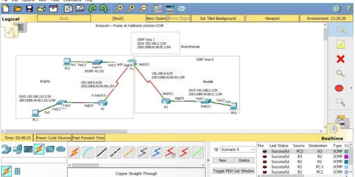
Una empresa de confecciones posee tres sucursales distribuidas en las ciudades de Bogotá, Medellín y Bucaramanga, en donde el estudiante será el administrador de la red, el cual deberá configurar e interconectar entre sí cada uno de los dispositivos que forman parte del escenario, acorde con los lineamientos establecidos para el direccionamiento IP, protocolos de enrutamiento y demás aspectos que forman parte de la topología de red.
Figura 1.Escenario 1.
Configurar la topología de red, de acuerdo con las siguientes especificaciones.
Parte 1. Configuración del escenario propuesto
1. Configurar las interfaces con las direcciones IPv4 e IPv6 que se muestran en la topología de red.
DCE según sea apropiado.
3. En R2 y R3 configurar las familias de direcciones OSPFv3 para IPv4 e IPv6. Utilice el identificador de enrutamiento 2.2.2.2 en R2 y 3.3.3.3 en R3 para ambas familias de direcciones.
4. En R2, configurar la interfaz F0/0 en el área 1 de OSPF y la conexión serial entre R2 y R3 en OSPF área 0.
5. En R3, configurar la interfaz F0/0 y la conexión serial entre R2 y R3 en OSPF área 0.
6. Configurar el área 1 como un área totalmente Stubby.
7. Propagar rutas por defecto de IPv4 y IPv6 en R3 al interior del dominio OSPFv3. Nota: Es importante tener en cuenta que una ruta por defecto es diferente a la definición de rutas estáticas.
8. Realizar la configuración del protocolo EIGRP para IPv4 como IPv6. Configurar la interfaz F0/0 de R1 y la conexión entre R1 y R2 para EIGRP con el sistema autónomo 101. Asegúrese de que el resumen automático está desactivado.
9. Configurar las interfaces pasivas para EIGRP según sea apropiado.
10. En R2, configurar la redistribución mutua entre OSPF y EIGRP para IPv4 e IPv6. Asignar métricas apropiadas cuando sea necesario.
11. En R2, de hacer publicidad de la ruta 192.168.3.0/24 a R1 mediante una lista de distribución y ACL.
Parte 2: Verificar conectividad de red y control de la trayectoria
1. Registrar las tablas de enrutamiento en cada uno de los routers, acorde con los parámetros de configuración establecidos en el escenario propuesto.
2. Verificar comunicación entre routers mediante el comando ping y traceroute.
3. Verificar que las rutas filtradas no están presentes en las tablas de enrutamiento de los routers correctas.
2.1.2. Solución escenario 1
PARTE 1
1. Configuración interfaces
CONFIGURACIÓN R1
Router>ena Router#confi term
Router# confi term
Enter configuration commands, one per line. End with CNTL/Z. Router(config)#hostname R1
R1(config)#interface gigabitEthernet 0/0
R1(config-if)#ip address 192.168.110.1 255.255.255.0 R1(config-if)#ipv6 address 2001:DB8:ACAD:110::1/64 R1(config-if)#NO SHUTdown
R1(config-if)#
%LINK-5-CHANGED: Interface GigabitEthernet0/0, changed state to up
%LINEPROTO-5-UPDOWN: Line protocol on Interface GigabitEthernet0/0, changed state to up
R1(config-if)#EXIT
R1(config)#INterface Serial 0/0/0
R1(config-if)#
%LINK-5-CHANGED: Interface Serial0/0/0, changed state to up
R1(config-if)#EXIT R1(config)#
%LINEPROTO-5-UPDOWN: Line protocol on Interface Serial0/0/0, changed state to up
R1(config)#EXIT R1#
%SYS-5-CONFIG_I: Configured from console by console
R1#W
Building configuration... [OK]
R1#
CONFIGURACIÓN R2 R2#CONFI TERMI
Enter configuration commands, one per line. End with CNTL/Z. R2(config)#HOStname R2
R2(config)#interface gigabitEthernet 0/0
R2(config-if)#ip address 192.168.2.1 255.255.255.0 R2(config-if)#ipv6 address 2001:DB8:ACAD:B::1/64
%GigabitEthernet0/0: Error: 2001:DB8:ACAD:B::/64 is overlapping with 2001:DB8:ACAD:B::/64 on Serial0/0/0
R2(config-if)#NO SHUTdown R2(config-if)#EXIT
R2(config-if)#IP ADdress 192.168.9.2 255.255.255.252 R2(config-if)#IPV6 ADdress 2001:DB8:ACAD:90.2/64 % Incomplete command.
R2(config-if)#IPV6 ADdress 2001:DB8:ACAD:90::2/64 R2(config-if)#NO SHUTdown
R2(config-if)#EXIT R2(config)#EXIT R2#
%SYS-5-CONFIG_I: Configured from console by console
R2#W
Building configuration... [OK]
R2# R2#
R2(config)#INTerface S
R2(config)#INTerface Serial 0/0/1
R2(config-if)#IP ADdress 192.168.9.5 255.255.255.252 R2(config-if)#IPV6 ADdress 2001:DB8:ACAD:91::1/64 R2(config-if)#NO SHUtdown
%LINK-5-CHANGED: Interface Serial0/0/1, changed state to down R2(config-if)#
R2(config-if)#EXIT R2(config)#END R2#
R2#
CONFIGURACIÓN R3
R3>ena R3#confi term
Enter configuration commands, one per line. End with CNTL/Z. R3(config)#HOStname R3
R3(config)#interface gigabitEthernet 0/0 R3(config-if)#ip ad
R3(config-if)#ip address 192.168.3.1 255.255.255.0 R3(config-if)#ipv6 address 2001:DB8:ACAD:C::1/64 R3(config-if)#NO SHUtdown
R3(config-if)#
%LINK-5-CHANGED: Interface GigabitEthernet0/0, changed state to up
%LINEPROTO-5-UPDOWN: Line protocol on Interface GigabitEthernet0/0, changed state to up
R3(config-if)#EXIT
R3(config)#INTerface Serial 0/0/1
R3(config-if)#IPV 192.168.9.6 255.255.255.252 ^
% Invalid input detected at '^' marker.
R3(config-if)#ipv6 address 2001:DB8:ACAD:91::2/64 R3(config-if)#NO SHUtdown
R3(config-if)#
%LINK-5-CHANGED: Interface Serial0/0/1, changed state to up
R3(config-if)#
%LINEPROTO-5-UPDOWN: Line protocol on Interface Serial0/0/1, changed state to up
R3(config-if)#EXIT R3(config)#EXIT R3#
%SYS-5-CONFIG_I: Configured from console by console
R3#W
Building configuration... [OK]
Figura 2. Configuración interfaces.
2. Ancho de banda a 128 kbps en R1, R2, y R3 y ajustar la velocidad de reloj de DCE.
R1
R1(config)#INTerface Serial 0/0/0 R1(config-if)#clock rate 128000 R1(config-if)#bandwidth 128 R1(config-if)#no sh
R1(config-if)#no shutdown R1(config-if)#exit
R1(config)#
R2
R2(config)#INTerface Serial 0/0/0 R2(config-if)#BAndwidth 128
R2(config)#EXIT
R2(config)#INTerface Serial 0/0/1
R2(config-if)#CLOC R
R2(config-if)#CLOC Rate 128000 R2(config-if)#BA
R2(config-if)#BAndwidth 128 R2(config-if)#EXIT
R2(config)#
R3
R3(config)#interface serial 0/0/1 R3(config-if)#b
R3(config-if)#bandwidth 128 R3(config-if)#exit
R3(config)#
3. En R2 y R3 direcciones OSPFv3 para IPv4 e IPv6. Utilice el identificador de enrutamiento 2.2.2.2 en R2 y 3.3.3.3 en R3 para ambas familias de direcciones. 4. En R2, configurar la interfaz F0/0 en el área 1 de OSPF y la conexión serial entre
R2 y R3 en OSPF área.
R2
R2(config)#router ospf 1 R2(config-router)#router
R2(config-router)#router-id 2.2.2.2
5. En R3, configurar la interfaz F0/0 y la conexión serial entre R2 y R3 en OSPF área 0.
R3
R3#confi term
Enter configuration commands, one per line. End with CNTL/Z. R3(config)#router ospf 1
R3(config-router)#router
R3(config-router)#router-id 3.3.3.3 R3(config-router)#net
R3(config-router)#network 192.168.9.4 0.0.0.3 area 1 R3(config-router)#net
R3(config-router)#network 192.168.3.0 0.0.0.255 % Incomplete command.
R3(config-router)#network 192.168.3.0 0.0.0.255 area 1 R3(config-router)#exit
6. Configurar el área 1 como un área totalmente Stubby.
R2>ena
R2# confi term
Enter configuration commands, one per line. End with CNTL/Z. R2(config)#router ospf 1
R2(config-router)#area 1 stub R2(config-router)#exit
7. Propagar rutas por defecto de IPv4 y IPv6 en R3 al interior del dominio OSPFv3. Nota: Es importante tener en cuenta que una ruta por defecto es diferente a la definición de rutas estáticas.
8. Realizar la configuración del protocolo EIGRP para IPv4 como IPv6. Configurar la interfaz F0/0 de R1 y la conexión entre R1 y R2 para EIGRP con el sistema autónomo 101. Asegúrese de que el resumen automático está desactivado. 9. Configurar las interfaces pasivas para EIGRP según sea apropiado.
10. En R2, configurar la redistribución mutua entre OSPF y EIGRP para IPv4 e IPv6. Asignar métricas apropiadas cuando sea necesario.
R1(config)#router eig
R1(config)#router eigrp 101
R1(config-router)#no auto-summary
R1(config-router)#network 192.168.9.0 0.0.0.3 R1(config-router)#network 192.168.110.0 0.0.0.255 R1(config-router)#network 192.168.2.0 0.0.0.255 R1(config-router)#exit
R1(config)#exit R1#
11. En R2, de hacer publicidad de la ruta 192.168.3.0/24 a R1 mediante una lista de distribución y ACL.
R2(config)#access-list 1 perm 192.168.3.0 R2(config)#access-list 1 perm any
R2(config)#router eigrp 101
PARTE 2. Verificar conectividad de red y control de la trayectoria
Figura 3.Conectividad de red.
Pin R2 A R3 Y R1
Ping R1 a R2 y R3
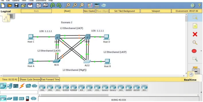
2.2. Escenario 2
2.2.1. Planteamiento del problema
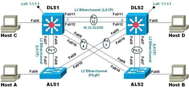
Una empresa de comunicaciones presenta una estructura Core acorde a la topología de red, en donde el estudiante será el administrador de la red, el cual deberá configurar e interconectar entre sí cada uno de los dispositivos que forman parte del escenario, acorde con los lineamientos establecidos para el direccionamiento IP, etherchannels, VLANs y demás aspectos que forman parte del escenario propuesto.
Figura 6. Escenario 2.
Parte 1. Configurar la red de acuerdo con las especificaciones.
1. Apagar todas las interfaces en cada switch.
2. Asignar un nombre a cada switch acorde al escenario establecido.
3. Configurar los puertos troncales y Port-channels tal como se muestra en el diagrama.
a. La conexión entre DLS1 y DLS2 será un EtherChannel capa-3 utilizando LACP. Para DLS1 se utilizará la dirección IP 10.12.12.1/30 y para DLS2 utilizará 10.12.12.2/30.
c. Los Port-channels en las interfaces F0/9 y fa0/10 utilizará PAgP.
d. Todos los puertos troncales serán asignados a la VLAN 800 como la VLAN nativa.
4. Configurar DLS1, ALS1, y ALS2 para utilizar VTP versión 3
a. Utilizar el nombre de dominio UNAD con la contraseña cisco123 b. Configurar DLS1 como servidor principal para las VLAN.
c. Configurar ALS1 y ALS2 como clientes VTP.
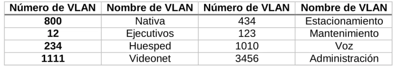
5. Configurar en el servidor principal las siguientes VLAN:
Tabla 1. VLAN para servidores.
Número de VLAN Nombre de VLAN Número de VLAN Nombre de VLAN
800 Nativa 434 Estacionamiento
12 Ejecutivos 123 Mantenimiento
234 Huesped 1010 Voz
1111 Videonet 3456 Administración
6. En DLS1, suspender la VLAN 434.
7. Configurar DLS2 en modo VTP transparente VTP utilizando VTP versión 2, y configurar en DLS2 las mismas VLAN que en DLS1.
8. Suspender VLAN 434 en DLS2.
9. En DLS2, crear VLAN 567 con el nombre de CONTABILIDAD. La VLAN de CONTABILIDAD no podrá estar disponible en cualquier otro Switch de la red.
10. Configurar DLS1 como Spanning tree root para las VLAN 1, 12, 434, 800, 1010, 1111 y 3456 y como raíz secundaria para las VLAN 123 y 234.
11. Configurar DLS2 como Spanning tree root para las VLAN 123 y 234 y como una raíz secundaria para las VLAN 12, 434, 800, 1010, 1111 y 3456.
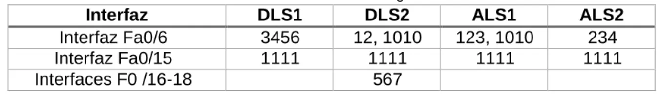
12. Configurar todos los puertos como troncales de tal forma que solamente las VLAN que se han creado se les permitirá circular a través de éstos puertos.
Tabla 2. Interfaces a configurar.
Interfaz DLS1 DLS2 ALS1 ALS2
Interfaz Fa0/6 3456 12, 1010 123, 1010 234
Interfaz Fa0/15 1111 1111 1111 1111
Interfaces F0 /16-18 567
14. Todas las interfaces que no sean utilizadas o asignadas a alguna VLAN deberán ser apagadas.
15. Configurar SVI en DLS1 y DLS2 como soporte de todas las VLAN y de enrutamiento entre las VLAN. Utilice la siguiente tabla para las asignaciones de subred:
Tabla 3. Asignaciones de subred. VLAN Nombre de
VLAN Subred VLAN
Nombre de VLAN
Subred
12 Ejecutivos 10.0.12.0/24 123 Mantenimiento 10.0.123.0/24 234 Huespedes 10.0.234.0/24 1010 Voz 10.10.10.0/24 1111 Videonet 10.11.11.0/24 3456 Administración 10.34.56.0/24
DLS1 siempre utilizará la dirección .252 y DLS2 siempre utilizará la dirección .253 para las direcciones IPv4.
La VLAN 567 en DLS2 no podrá ser soportada para enrutamiento.
16. Configurar una interfaz Loopback 0 en DLS1 y DLS2. Esta interfaz será configurada con la dirección IP 1.1.1.1/32 en ambos Switch.
17. Configurar HSRP con interfaz tracking para las VLAN 12, 123, 234, 1010, y 1111.
a. Utilizar HSRP versión 2
b. Crear dos grupos HSRP, alineando VLAN 12, 1010, 1111, y 3456 para el primer grupo y las VLAN 123 y 234 para el segundo grupo.
c. DLS1 será el Switch principal de las VLAN 12, 1010, 1111, y 3456 y DLS2 será el Switch principal para las VLAN 123 y 234.
d. Utilizar la dirección virtual .254 como la dirección de Standby de todas las VLAN
18. Configurar DLS1 como un servidor DHCP para las VLAN 12, 123 y 234
c. Establecer como default-router las direcciones virtuales HSRP para cada VLAN
19. Obtener direcciones IPv4 en los host A, B, y D a través de la configuración por DHCP que fue realizada.
Parte 2. Conectividad de red de prueba y las opciones configuradas.
1. Verificar la existencia de las VLAN correctas en todos los switches y la asignación de puertos troncales y de acceso
2. Verificar que el EtherChannel entre DLS1 y ALS1 está configurado correctamente
3. Verificar la configuración de Spanning tree entre DLS1 o DLS2 para cada VLAN.
4. Verificar configuraciones HSRP mediante comandos Show
2.2.2. Solución escenario 2
PARTE 1. Configurar la red de acuerdo con las especificaciones.
ALS1
Switch(config)#interface fastEthernet0/1 Switch(config-if)#switchport mode access
Switch(config-if)#switchport port-security maximum 1 Switch(config-if)#exit
Switch(config)#exit Switch#
DSL2
Switch>enable
Switch#configure terminal
DLS2(config)#INTerface fastEthernet 0/1 DLS2(config-if)#switchport mode access
DLS2(config-if)#switchport port-security maximum 1 DLS2(config-if)#exit
DLS2(config)#exit DLS2#
%SYS-5-CONFIG_I: Configured from console by console
DLS2#
ALS1
Switch#configure terminal
Enter configuration commands, one per line. End with CNTL/Z. Switch(config)#hostname ALS1
ALS1(config)#INTerface fastEthernet 0/1 ALS1(config-if)#switchport mode access
ALS1(config-if)#switchport port-security maximum 1 ALS1(config-if)#EXIT
ALS1(config)#EXIT ALS1#
%SYS-5-CONFIG_I: Configured from console by console
ALS1#
ALS2
Switch>enable
Switch#configure terminal
Switch(config)#hostname ALS2
ALS2(config)#INTerface fastEthernet 0/1 ALS2(config-if)#switchport mode access
ALS2(config-if)#switchport port-security maximum 1 ALS2(config-if)#EXIT
ALS2(config)#EXIT ALS2#
%SYS-5-CONFIG_I: Configured from console by console
ALS2#
Figura 7. Solución escenario 2.
PUERTOS TRONCALES Y VLAN NATIVA 800
ALS1 ALS1#
ALS1#CONFI TERM
ALS1(config)#vtp mode ser ALS1(config)#vtp mode server Device mode already VTP SERVER. ALS1(config)#int ran f0/7-12
ALS1(config-if-range)#switchport trunk native vlan 800
ALS1(config-if-range)#switchport trunk allowed vlan except 1999 ALS1(config-if-range)#switchport mode trunk
ALS1(config-if-range)#
%LINEPROTO-5-UPDOWN: Line protocol on Interface FastEthernet0/7, changed state to down
%LINEPROTO-5-UPDOWN: Line protocol on Interface FastEthernet0/7, changed state to up
%LINEPROTO-5-UPDOWN: Line protocol on Interface FastEthernet0/8, changed state to down
%LINEPROTO-5-UPDOWN: Line protocol on Interface FastEthernet0/8, changed state to up
%LINEPROTO-5-UPDOWN: Line protocol on Interface FastEthernet0/9, changed state to down
%LINEPROTO-5-UPDOWN: Line protocol on Interface FastEthernet0/9, changed state to up
%LINEPROTO-5-UPDOWN: Line protocol on Interface FastEthernet0/10, changed state to up
ALS1(config-if-range)#switchport nonegotiate ALS1(config-if-range)#no shutdown
ALS1(config-if-range)#exit ALS1(config)#
ALS1(config)#
ALS2
ALS2(config)#vtp mode server Device mode already VTP SERVER. ALS2(config)#int ran f0/7-12
ALS2(config-if-range)#int ran f0/6-12
ALS2(config-if-range)#switchport trunk native vlan 800
ALS2(config-if-range)#switchport trunk allowed vlan except 1999 ALS2(config-if-range)#switchport mode trunk
ALS2(config-if-range)#
%LINEPROTO-5-UPDOWN: Line protocol on Interface FastEthernet0/6, changed state to down
%LINEPROTO-5-UPDOWN: Line protocol on Interface FastEthernet0/6, changed state to up
%LINEPROTO-5-UPDOWN: Line protocol on Interface FastEthernet0/7, changed state to down
%LINEPROTO-5-UPDOWN: Line protocol on Interface FastEthernet0/8, changed state to down
%LINEPROTO-5-UPDOWN: Line protocol on Interface FastEthernet0/8, changed state to up
%LINEPROTO-5-UPDOWN: Line protocol on Interface FastEthernet0/9, changed state to down
%LINEPROTO-5-UPDOWN: Line protocol on Interface FastEthernet0/9, changed state to up
%LINEPROTO-5-UPDOWN: Line protocol on Interface FastEthernet0/10, changed state to down
%LINEPROTO-5-UPDOWN: Line protocol on Interface FastEthernet0/10, changed state to up
ALS2(config-if-range)#switchport nonegotiate ALS2(config-if-range)#NO SHUTDOWN ALS2(config-if-range)#
ALS2(config-if-range)#EXIT ALS2(config)#EXIT
ALS2#
%SYS-5-CONFIG_I: Configured from console by console
DLS1 SITCH 3560 CISCO
Switch(config)#int ran f0/6-12
Switch(config-if-range)#switchport trunk native vlan 800
Switch(config-if-range)#switchport trunk allowed vlan except 1999
Switch(config-if-range)#%SPANTREE-2-RECV_PVID_ERR: Received 802.1Q BPDU on non trunk FastEthernet0/9 VLAN800.
%SPANTREE-2-BLOCK_PVID_LOCAL: Blocking FastEthernet0/9 on VLAN0800. Inconsistent port type.
%SPANTREE-2-RECV_PVID_ERR: Received 802.1Q BPDU on non trunk FastEthernet0/10 VLAN800.
%SPANTREE-2-BLOCK_PVID_LOCAL: Blocking FastEthernet0/10 on VLAN0800. Inconsistent port type.
Switch(config-if-range)#switchport mode trunk
Command rejected: An interface whose trunk encapsulation is "Auto" can not be configured to "trunk" mode.
Command rejected: An interface whose trunk encapsulation is "Auto" can not be configured to "trunk" mode.
Command rejected: An interface whose trunk encapsulation is "Auto" can not be configured to "trunk" mode.
Command rejected: An interface whose trunk encapsulation is "Auto" can not be configured to "trunk" mode.
Command rejected: An interface whose trunk encapsulation is "Auto" can not be configured to "trunk" mode.
Command rejected: An interface whose trunk encapsulation is "Auto" can not be configured to "trunk" mode.
Command rejected: An interface whose trunk encapsulation is "Auto" can not be configured to "trunk" mode.
Switch(config-if-range)#switchport nonegotiate
Command rejected: Conflict between 'nonegotiate' and 'dynamic' status. Command rejected: Conflict between 'nonegotiate' and 'dynamic' status. Command rejected: Conflict between 'nonegotiate' and 'dynamic' status. Command rejected: Conflict between 'nonegotiate' and 'dynamic' status. Command rejected: Conflict between 'nonegotiate' and 'dynamic' status. Command rejected: Conflict between 'nonegotiate' and 'dynamic' status. Command rejected: Conflict between 'nonegotiate' and 'dynamic' status. Switch(config-if-range)#no shutdown
Switch(config-if-range)#exit Switch(config)#exit
Switch#
%SYS-5-CONFIG_I: Configured from console by console
Switch# Switch#
DLS2
DLS2(config)#vtp mode server Device mode already VTP SERVER. DLS2(config)#int ran f0/6-12
DLS2(config-if-range)#switchport trunk native vlan 800
DLS2(config-if-range)#switchport trunk allowed vlan except 1999
DLS2(config-if-range)#%SPANTREE-2-RECV_PVID_ERR: Received 802.1Q BPDU on non trunk FastEthernet0/8 VLAN800.
%SPANTREE-2-RECV_PVID_ERR: Received 802.1Q BPDU on non trunk FastEthernet0/7 VLAN800.
%SPANTREE-2-BLOCK_PVID_LOCAL: Blocking FastEthernet0/7 on VLAN0800. Inconsistent port type.
switchport mode trunk
Command rejected: An interface whose trunk encapsulation is "Auto" can not be configured to "trunk" mode.
Command rejected: An interface whose trunk encapsulation is "Auto" can not be configured to "trunk" mode.
Command rejected: An interface whose trunk encapsulation is "Auto" can not be configured to "trunk" mode.
Command rejected: An interface whose trunk encapsulation is "Auto" can not be configured to "trunk" mode.
Command rejected: An interface whose trunk encapsulation is "Auto" can not be configured to "trunk" mode.
Command rejected: An interface whose trunk encapsulation is "Auto" can not be configured to "trunk" mode.
Command rejected: An interface whose trunk encapsulation is "Auto" can not be configured to "trunk" mode.
DLS2(config-if-range)#
DLS2(config-if-range)#switchport nonegotiate
Command rejected: Conflict between 'nonegotiate' and 'dynamic' status. Command rejected: Conflict between 'nonegotiate' and 'dynamic' status. Command rejected: Conflict between 'nonegotiate' and 'dynamic' status. Command rejected: Conflict between 'nonegotiate' and 'dynamic' status. Command rejected: Conflict between 'nonegotiate' and 'dynamic' status. Command rejected: Conflict between 'nonegotiate' and 'dynamic' status. Command rejected: Conflict between 'nonegotiate' and 'dynamic' status. DLS2(config-if-range)#NO SHU
DLS2(config-if-range)#EXIT DLS2(config)#EXIT
DLS2#
%SYS-5-CONFIG_I: Configured from console by console
DLS2#
Figura 8. Configuración puertos.
CONFIGURACION DSL1 VLAN PRINCIPAL
Switch(config)#hostname DLS1 DLS1(config)#VLAN 800
DLS1(config-vlan)#NAME NATIVA DLS1(config-vlan)#VLAN 12
DLS1(config-vlan)#NAME EJECUTIVOS DLS1(config-vlan)#VLAN 234
VLAN_CREATE_FAIL: Failed to create VLANs 1111 : extended VLAN(s) not allowed in current VTP mode
DLS1(config)#111 VIDEONET ^
% Invalid input detected at '^' marker. DLS1(config)#VLAN 1111
VLAN_CREATE_FAIL: Failed to create VLANs 1111 : extended VLAN(s) not allowed in current VTP mode
DLS1(config)#NAME VIDEONET ^
% Invalid input detected at '^' marker. DLS1(config)#VLAN 111 DLS1(config-vlan)#NAME VIDEONET DLS1(config-vlan)#VLAN 434 DLS1(config-vlan)#NAME ESTACIONAMIENTO DLS1(config-vlan)#VLAN 123 DLS1(config-vlan)#NAME MANTENIMIENTO DLS1(config-vlan)#VLAN 1010
VLAN_CREATE_FAIL: Failed to create VLANs 1010 : extended VLAN(s) not allowed in current VTP mode
DLS1(config)#VLAN 101
DLS1(config-vlan)#NAME VOZ DLS1(config-vlan)#VLAN 3456
VLAN_CREATE_FAIL: Failed to create VLANs 3456 : extended VLAN(s) not allowed in current VTP mode
DLS1(config)#VLAN 345
DLS1(config-vlan)#NAME ADMINISTRACION DLS1(config-vlan)#EXIT
Figura 9. Configuración DLS 1.
INTERFACES VLAN
DSL1
CONFI TERM
Enter configuration commands, one per line. End with CNTL/Z. DLS1(config)#int
DLS1(config)#interface vlan 1 DLS1(config-if)#ip ad
DLS1(config-if)#ip address 10.12.12.1 255.255.255.252 DLS1(config-if)#no shut
DLS1(config-if)#no shutdown
DLS1(config-if)#
%LINK-5-CHANGED: Interface Vlan1, changed state to up
exit
DLS1(config)#exit DLS1#
DSL2
DLS2(config)#interface vl DLS2(config)#interface vlan 1 DLS2(config-if)#ip ad
DLS2(config-if)#ip address 10.12.12.2 255.255.255.252 DLS2(config-if)#exit
DLS2(config)#exit DLS2#
%SYS-5-CONFIG_I: Configured from console by console
DLS2# DLS2#
DLS2#confi term
Enter configuration commands, one per line. End with CNTL/Z. DLS2(config)#int
DLS2(config)#interface v DLS2(config)#interface vl DLS2(config)#interface vlan 1 DLS2(config-if)#no su
DLS2(config-if)#no sut DLS2(config-if)#no sh
DLS2(config-if)#no shutdown
%LINK-5-CHANGED: Interface Vlan1, changed state to up
%LINEPROTO-5-UPDOWN: Line protocol on Interface Vlan1, changed state to up
DLS2(config-if)# DLS2(config-if)# DLS2(config-if)#exit DLS2(config)# DLS2(config)# DLS2(config)#exit DLS2#
%SYS-5-CONFIG_I: Configured from console by console
DLS2# DLS2#w
Building configuration... [OK]
HOST A
Figura 10. Host A.
HOST B
HOST C
Figura 12. Host C.
HOST D
TOPOLOGIA EN RED ADSL PRINCIPAL
ALS1
ALS1(config)#interface vl ALS1(config)#interface vlan 1
ALS1(config-if)#ip address 192.168.1.1 255.255.255.0 ALS1(config-if)#exit
ALS1(config)#exit ALS1#
%SYS-5-CONFIG_I: Configured from console by console
ALS1#confi term
Enter configuration commands, one per line. End with CNTL/Z. ALS1(config)#interface vlan 1
ALS1(config-if)#no shutdown
ALS2
Enter configuration commands, one per line. End with CNTL/Z. ALS2(config)#interface vlan 1
ALS2(config-if)#ip address 192.168.2.1 255.255.255.0 ALS2(config-if)#no shutdown
ALS2(config-if)#
%LINK-5-CHANGED: Interface Vlan1, changed state to up
ALS2(config-if)# ALS2(config-if)#exit
CONCLUSIONES
En los procesos de encaminamiento de datos, es importante establecer un ejercicio jerárquico (ordenado) de configuración de equipos activos de red, en los que se tenga en cuenta los servicios que va ofrecer la red y las restricciones que incluyan aspectos de seguridad en la transmisión de datos.
El establecimiento de una conexión (negociación en tres pasos), (3-way handshake), se debe garantizar. Los ejercicios realizados en e simulador permiten recrear situaciones de conectividad con pruebas de escucha y respuesta básica (eco). Para garantizar efectivamente una transmisión sin pérdida de datos, se deben utilizar otras herramienta y protocolos de conexión.
Si bien es cierto que cada fabricante de equipos, crea sus propios algoritmos y código de trabajo (máquina – terminal - console), el hecho de tener claro e identificar las reglas de servicio y los protocolos con sus prestaciones, darán al administrador de red unas competencias a nivel de ingeniería que permita manipular efectivamente los equipos y maximizar sus características tanto técnicas como comerciales.
Para el caso de este trabajo, se usó el simulador de Cisco “acket Tracer” que nos recrea el mismo código que realmente traen los equipos físicos. Es una ventaja que nos ofrece para los administradores de red ya que Cisco es reconocida en el mercado de las telecomunicaciones. Conocer y caracterizar sus equipos, permite al administrador de red obtener las competencias básicas para afrontar escenarios futuros reales y con equipos de otras marcas.
BIBLIOGRAFÍA
CISCO. (2014). Exploración de la red. Fundamentos de Networking. Recuperado de
https://staticcourseassets.s3.amazonaws.com/ITN50ES/module1/index.html#1.0.1. 1
Froom, R., Frahim, E. (2015). CISCO Press (Ed). Fundamentals Review.
Implementing Cisco IP Switched Networks (SWITCH) Foundation Learning Guide CCNP SWITCH 300-115. Recuperado de
https://1drv.ms/b/s!AmIJYeiNT1IlnWR0hoMxgBNv1CJ
Froom, R., Frahim, E. (2015). CISCO Press (Ed). Spanning Tree Implementation. Implementing Cisco IP Switched Networks (SWITCH) Foundation Learning Guide CCNP SWITCH 300-115. Recuperado de
https://1drv.ms/b/s!AmIJYeiNT1IlnWR0hoMxgBNv1CJ
Macfarlane, J. (2014). Network Routing Basics: Understanding IP Routing in Cisco Systems. Recuperado de
http://bibliotecavirtual.unad.edu.co:2048/login?url=http://search.ebscohost.com/logi n.aspx?direct=true &db=e000xww&AN=158227&lang=es&site=ehost-live
Teare, D., Vachon B., Graziani, R. (2015). CISCO Press (Ed). EIGRP
Implementation. Implementing Cisco IP Routing (ROUTE) Foundation Learning Guide CCNP ROUTE 300-101. Recuperado de