Analysis, Reliability and Optimization of Reinforced Concrete 2-D Structures
A. Samartin Full Professor
Technical University of Madrid Madrid. Spain
Summary
P. Diaz-Dominguez Dr. Civil Engineer
European University of Madrid Madrid. Spain
J. Garcia-Palacios Associate Professor
Technical University of Madrid Madrid. Spain
In this paper a consistent analysis of reinforced concrete (RC) two-dimensional (2-D) structures, namely slab structures subjected to in-plane and out-plane forces, is presented. By using this method of analysis the well established methodology for dimensioning and verifying RC sections of beam structures is extended to 2-D structures. The validity of the proposed analysis results is checked by comparing them with some published experimental test results. Several examples show some of these proposed analysis features, such as the influence of the reinforcement layout on the ser vice and ultimate behavior of a slab structure and the non straightforward problem of the optimal dimension at a slab point subjected to several loading cases. Also, in these examples, the method applications to design situations as multiple steel families and non orthogonal reinforcement layout are commented.
Keywords: Reinforced concrete design, membrane and plate structures, nonlinear material analysis, Finite Element.
1. Introduction
As it is well known in a structural design three main steps can be distinguished. Typically an actual work is idealized into a structural model, i.e. a physical model or structure. By means of an analysis the behaviour of the structure can be studied. Then the results of the analysis, i.e. displacements, strains, stress and stress-resultants are interpreted and used in order to modify the designed work that means to change the geometrical and/or mechanical properties of the structure and therefore the properties of the actual work. The previous steps are again applied to the modified design in an iterative feedback process.
Independent on the use of the safety factors technique and the consideration of the two limit states (ULS and SLS) or the more sophisticated and elaborated theory of reliability, the analysis should be able to simulate with sufficient accuracy the actual behaviour of the designed work at every potential loading level between SLS and ULS. The current computer capability allow us to develop this type of analysis and dimension technique. Moreover, the above mentioned feedback iterative design proce dure can be avoided by introducing optimization techniques. Several commercial computer programs have these capabilities as standard, but usually for simple materials only. Typically reinforced con crete structures design is not completely consistent, because these structures are analyzed as linear elastic but their sections are dimensioned by assuming a nonlinear behaviour for both materials con crete and steel. This is particularly true when the structure is 2-D dimensional, i.e. a plate or a shell structures.
In this paper a consistent method of analysis is shown. The method has been developed in order to replicate the actual behaviour of an arbitrary reinforced concrete 2-D slab structure subjected to both in-plane and out-plane forces. The acting load on the slab is assumed to increase monotonically from zero to ultimate load. The concrete material behaviour was supposed to have a 20 behaviour and tension stiffening has been also introduced as an approximation. The method has been developed by the authors along the last years and it is used currently as a post-processor of some commercial computer programs.
The paper will be organized as follows. In the first section a short summary of the main steps of the method will be presented. Details of the method derivation can be seen in other publications of the authors [1 O], [8] and [11 ]. In the following sections some model features and capabilities will be emphasized. Finally, some conclusive remarks will be given.
2. Consistent nonlinear analysis of RC slab structures 2.1 Basic equations
The model derivation is based on fundamental elasticity equations i.e. compatibility, equilibrium and constitutive equations. The more important and difficult task in this derivation corresponds to the formulation of the RC constitutive equations. In the constitutive equations of the slab element the reinforcement layout is explicitly taken into account, i.e. orthogonal or skew reinforcement layouts or multiple reinforcement families are considered. In order to simplify the formulation of the constitutive equations and therefore the analysis, two cases are developed. The first case corresponds to ULS and simple constitutive equations are used and in the second case more elaborated equations are used and they can be applied for both ULS and SLS.
The RC slab constitutive equations can be transformed into a discrete formulation by defining a RC slab constitutive matrix D. This matrix relates the stress resultants vector containing the in-plane forces Nij and out-plate forces Mij (figure 1) to the corresponding membrane Eij and bending "'ij strains at a given point of the slab. The RC slab constitutive matrix will be derived assuming is sum of the membrane stiffness matrix and plate stiffness matrix. Finally, in the derivation of the RC .slab constitutive matrix D the material nonlinearity should taken into account. Moreover, a tangent RC slab constitutive matrix Dt should be derived in order to handle incrementally a nonlinear analysis.
Figure I: Slab stress-resultants positive directions
ULS and SLS will be assumed here:
• The differential RC slab element is subjected to a constant field of applied forces.
• External loads are monotonically increasing applied.
• Displacements between bar ends and adjacent concrete are equal (Smeared model).
• Steel bars resist only longitudinal forces.
• Cracks remains orthogonal to the tension stress principal direction (Rotating angle hypothesis).
For the ULS the following additional hypotheses are assumed:
• The stress resultants are known. Typically computed using a linear elastic analysis.
• Aggregated interlock is not considered.
• Tension stresses can not be resisted by concrete.
• Tension stiffening is not taken into account.
• The influence of a 2-D stress state on the concrete behavior is not considered.
Then in general the concrete constitutive equations can be written as functions of the principal stresses in the concrete aci expressed in terms of the principal strains of the concrete as follows:
(1)
In equation (1) the concrete stresses are assumed, as usual in practice, to be positive if compression.
Similarly, the constitutive equation for the reinforcement family k gives the bar force sk. either com pression or tension, according to the expression:
(2)
where Esk is the strain of the steel bar of family k.
Figure 2: (a) Reinforcement disposition. (b) Transfer mechanism of the stress resultants
Cij = aij(x3)dx3 and Sij = aij(x3dx3) are the external forces, the concrete strength forces and the steel strength forces respectively acting on the slice.
Using a stiffness formulation, i.e. applying standard elasticity transformations, the equilibrium equa tions can be integrated across the slab thickness and expressed in terms of the basic unknowns r
the following system of nonlinear equations is reached:
D(r) = uo (3)
In equation (3) the 6 x 1 vector r =
(cS,cg,0°,,..�,,..g,cp0)r
contains all the basic unknowns. The in-plane unknowns are the principal strainsc�, cg
at slab middle plane x3 = O ando0
is the angle between the direction of thec�
and the axis x1. Similarly the out-plane unknowns are the principal curvatures,..�, ,..g
and cp0 is the angle between direction of the principal curvature"'�
and the axis x1.All the acting external stress resultants are collected in the vector u0, where
and D(r) = [Di(r)], i = 1, 2, .. . , 6 a column vector of 6 x 1 dimension.
2.2 RC slab constitutive tangent matrix
In order to handle the nonlinearity of the system (3), a matrix incremental equilibrium equation should be obtained. Then by taking derivatives the following matrix equation be reached
Dtdr = du (4)
in which the RC slab constitutive tangent matrix is given by the expression Dt =
��
and du = d>.u0with >. a monotonically increased amplification factor.
2.3 Finite Element model
The RC slab constitutive matrix D and the RC slab constitutive tangent matrix Dt of a slab struc tural element can be integrated into a general FE computer program, using relatively straightforward mathematical manipulations. Technical details arising in a FE formulation are not discussed here and they can be seen in many classical books as [12] or [2]. Only final main results will be summarized.
• The basic unknowns vector r is related to the strain vector e according an expression of this type, given by the theory of Elasticity:
(5)
The expression (5) has an inverse r = c-1(e) and equation (3) can be written in terms of the strain vector as:
u = D(r) � u = D(c-1(e)) � u = D(e)
Similarly the incremental form of (5) can be expressed as follows:
dC
de = drdr = C(r)dr
(6)
(7)
and then the RC slab constitutive tangent matrix equation, (4),du = Dtde, can be modified in terms of the new basic unknowns:
(8)
• The field vector d(x1,x2) = (u1(xi,x2),u2(x1,x2),u3(x1,x2)f variation in a slab element in a local coordinate system can expresses as:
(9)
with N a matrix containing the shape functions corresponding to in plane and out of slab be havior respectively. The vector U contains the displacements and rotations at element nodes. The element strain vector is given by the expression:
< = BU where < =
[
:�
]
and B = Ld (xi, x,) with L a differential operator ( 10)• The application of the Principle of the virtual work between the external forces pe = (Pi) and the stress resultants in an element leads:
pe =
r
BT udx1dx2 =r
BTD(r)dx1dx2 =1
BTD[C(e)]dx1dx2 (11)k
ke
�As e = Bue the equilibrium expression (11) can be modified in order to emphasize its depen dence on the unknown displacement vector ue as follows:
pe =
1
BTD[Ve]dx1dx2 =Ke(Ue) fie
(12)
Similarly, the element tangential stiffness matrix K� is derived and the following final results are reached:
dPe =
[In.
BTDtBdx1dx2]
dUe = KHUe)dUe (13)Usually, the evaluation of the integrals (12) and ( 1 3) is carried out numerically. In the application examples presented below either triangular or quadrilateral elements and 9 integration Gauss points have been used.
Once the matrices Ke and K� are obtained and assembled for the whole structure at each load level a incremental-iterative nonlinear analysis of a RC slab structure can be performed.
In this way, it is possible to find displacements and stress resultants of a slab structure taking into account the reinforcement layout and the nonlinear behavior of the RC material.
3. Validation.
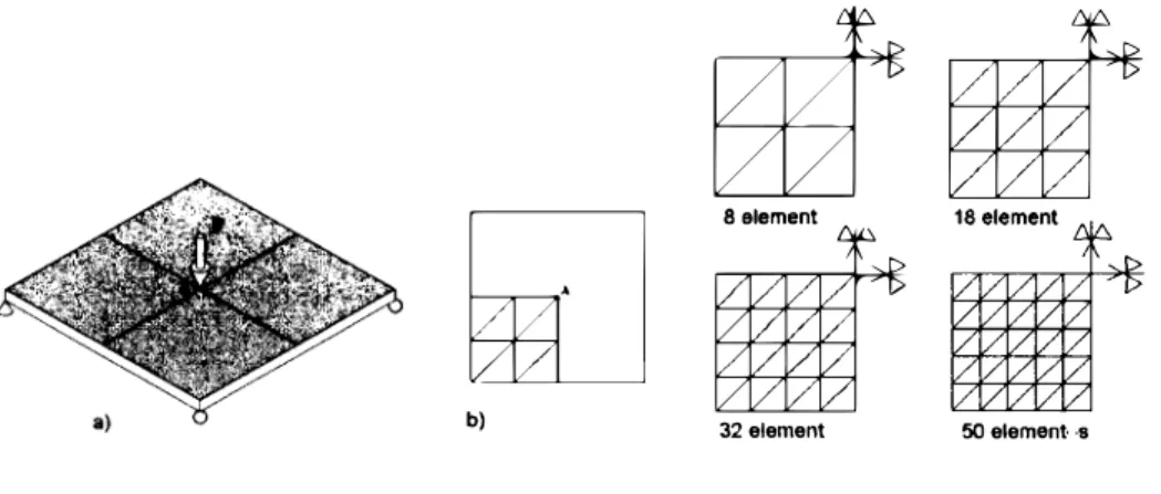
First, in order to validate the program a simple example will be presented. A reinforced concrete square plate supported at its corners under punctual load shown in figure 3a has been experimentally studied in [5]. The plate has an isotropic reinforcement. The material behaviour is non linear for
��§t
�itlt
b) 32
element 50 element· ·S
Figure 3: (a) Square plate supported at its corners (b) Different FE meshes
--=- ... ___ .,..._...,. _,,_ -·-
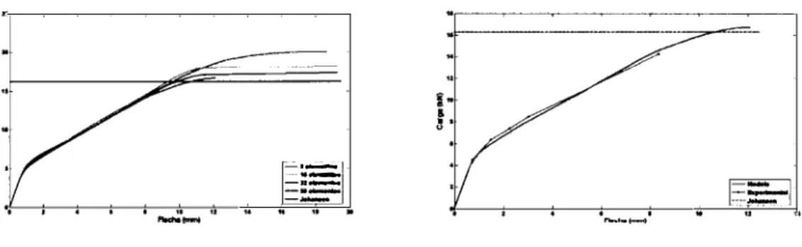
--Figure 4: (a) Ultimate load versus number of elements (b) Comparison between experimental test and analysis
4. Dimension features of RC 2-D structures.
4.1 Uniqueness of the reinforcement dimension solution
Contrary to the dimension of a RC beam the dimension of a RC 2-D structure subjected to a set of stress resultants, Nii and Mii (i, j = x, y) there is no an unique solution for the necessary reinforce ment to resist these forces.
Also the possibility to change the reinforcement layout can produce a different total reinforcement amount in order to resist the external stress resultants acting at a slab point. In the references [6] and [7] examples of the total reinforcement variation as function of the relative angles between the two reinforcement families are given.
Finally, the use of more than two reinforcement families can be also handled in the method and with this possibility can reduce the total reinforcement at singular points of the slab as corners. In these points extra reinforcement may be needed.
5. Several hypotheses treatment.
5.1 General approach
In the dimensioning procedure presented in this section, as is used in most of the current codes, it is imposed a minimum quantity of steel to be placed in each direction to resist the external stress resultants. It is supposed that the bar layout, the number of families N and their directions are known (slab thickness is also a datum). To solve the problem of total reinforcement optimization the Steepest Descent Method is used. The optimization problem to be solved is then summarized by the equation (14):
N
OF=
L
Ak (14)k=l
in which OF is the objective function, i. e. the total steel amount, to be minimized.
computed safety coefficient for each loading hypothesis
j
is>..1, j =
1, 2,... , m,
then for each loadingcase the condition to be fulfilled can be expressed as follows:
>..1(A) �
1 ___.>..1(A) -
1�
0 withj =
1, 2,... , m
where
A = (Ai, A2,
• • .,AN)
is the steel amount for each family and N is the number of families. (15)As have been assumed before, the reinforcement amount to each family has to be greater than a predeterminate value:
Ak �Amin
k = 1, 2, ... , N (16)The problem of function optimization (1 4) constrained with different conditions (15) and (16) has been discussed in many text books (see [3], [4], [1 ]). Here the optimal solution is achieved using the so-called penalty function. By this procedure the new objective function is:
where the function
81
is:and r is a penalty constant.
N
m
OF= L Ak
+ rL 81(l - >..1)2
k=i
1=i
81 =
1 if (1- >..1) �
081 =
0 if (1- >..1)
< 0In the two following sections the application of this approach will be illustrated.
5.2 Steel design of an element
(17)
The structural design method presented above was based on the assumption that the best design was the one able to resist a specified set of stress-resultants combination with the minimum rein forcement steel. In this section a practical example is shown. The example corresponds to the steel optimization of a 200
mm
membrane thickness element subjected to three different load combinations. The reinforcement is supposed to be placed orthogonally following the element
Oxi
andOx2
axes. The constitutive equations considered for the concrete and steel are shown in figure 5.First, for comparative purposes, the optimization is obtained by considering each of the three stress resultants combinations independently, i.e. assuming that in each case only one of them is acting on the element. The solutions obtained are shown in the three first rows of table 1, where the safety coefficient calculated to each load case is given.
Very often in design the maximum value among the values calculated to each reinforcement family by an independent analysis is taken for the combined load. In this way, the steel amount to be placed in each direction should be
Ai =
5.909mm2 /mm, A2 =
8.471mm2 /mm,
that is a total amountLOADS
N., Ho2 N12
1.00, -1.00, 2.00 0.00, 1.00, 1.00 -1.30, 2.00, 2.30
STEEL
�u=20 mm/m
CONCRETE
£0=2. 67 rnrn/m
Figure 5: Example I. Element and material characteristics
I
CaseI
AiI
A2
I
>.1I
>.2I
>.3I
ArI
Nl5.909 2.093 0.999 0.74 0.52 8.002
N2
1.998 4.001 0.520 1.00 0.69 5.999
N3
2.132 8.471 0.630 1.66 0.99 10.603
I
N1 4.163 1 9.221 1 i.003 I 3.29 I o.98 113.384 I
Table
1:
Example1.
Comparative analysis resultsis shown in the fourth row of the table 1 and it can be observed that the obtained value Ar 13.384
mm2 /mm
is an absolute obtained minimum.Comparing the value obtained by considering the three load cases independently with the total amount shown in the fourth row, it can be seen that the optimization procedure considering all the loading combinations gives a smaller total steel quantity.
6. Standard and consistent designs.
In this section standard and consistent designs of RC slabs will be compared. In the standard design stress analysis is carried out assuming a linear elastic material behaviour and the results of this analysis are independent on the steel reinforcement density and layout. By the contrary, in the second design procedure a consistent stress analysis is applied, i.e. nonlinear RC behaviour is considered. In both types of designs dimension is usually performed by assuming nonlinear constitutive laws for both materials concrete and reinforcement steel. Structural safety is given in the standard design by the safety factor of the section subjected to the worst stress-resultants combination. In a consistent design the safety factor can be computed by analyzing the whole RC structure in which the concrete and steel nonlinearities are taken into account and the actual steel reinforcement layout and density at each slab point are considered.
edges (figura 6), can illustrate this situation and also the influence of the layout reinforcement in the stress analysis.
Figure 6: (a) Slab geometric definition L = 14 m, B = 12 m, h = 0.94 m and a = 60 sex. degrees
This slab bridge is subjected to the dead load (self weight and permanent load) and as live load an uniform load and a extraordinary vehicle. All these loads are multiplied by the corresponding safety coefficients as it is specified in the Spanish Norm IAP1 999. Two steel reinforcement layouts have been designed. The orthogonal layout is the usually recommended one, longitudinal reinforcement direction coincides with the longitudinal axis of the bridge and the transversal reinforcement direction is orthogonal to the longitudinal one. The non-orthogonal layout, can be designed in bridge with large skewness. In this layout longitudinal reinforcement direction is the same as in the case of the orthogonal layout, but the transversal direction is parallel to the support lines along the abutments. A linear elastic analysis using FEM has been using in order to obtain the stress-resultants on the skew slab. Using these analysis results reinforcement steel density in mm2
/m
for the two layouts have been obtained. In the steel dimension the criterion of the minimum amount of steel needed to resist the different loading hypotheses with the specified safety has been used as a criterion. In figures 7 and 8 the longitudinal and transversal reinforcement steel densities on the bottom face are shown. The steel densities on the top slab face correspond to the minimum specified by the Spanish Concrete Code.The steel distribution shown in figures 7 and 8 is materialized in practice as a set of slab domains, each of them with constant steel reinforcement distribution as it is indicated in 9. Using this rein forcement layout and densities a material nonlinear stress analysis is carried out. In this way a rather realistic safety factor for the whole structure, in which stress redistribution are considered, can be computed.
As a result of this nonlinear stress slab analysis the path relating the load factor (.A) and the deflection ( �) in
mm
at center point of the slab is shown in figure 1 O for the two reinforcement layouts.NON ORTHOGONAL ORTHOGONAL
I!
-
·
0.0 0.5 1.0 1.S 2.0 2.S 3.0 3.S 4.0 4.S 0.0 O.S 1.0 1.S 2.0 2.S 3.0 3.S 4.0 4.S
Figure 7: longitudinal reinforcement steel density mm2 / m for orthogonal and non-orthogonal layouts.
N9N OfID!OGONAL
TWI
,
0.8 1.0 1.2 1.4 1.6 l.8 2.0 2.2 2.4
Figure 8: Transversal reinforcement steel density mm2 /m for orthogonal and non-orthogonal layouts.
stress-resultants distribution more anisotropic than for the orthogonal reinforcement design.
7. Summary and conclusions
In this paper a method to verify reinforced concrete in slab elements, that is based on constitutive, equilibrium and compatibility equations of Elasticity, is proposed. Using a set of adequate constitu
tive equations for concrete and reinforcement it is possible to predict accurately the RC membrane
8=12.00 m
I
·L=14.00 m
..
1
Figure 9: Actual steel densities distribution pattern for orthogonal and non orthogonal reinforcement layouts
•• 10 41 60 10 100
Olsplacement (mm)
>.,=1.95
>.,=1.64
-Onhogonal
-Non Onhogonal
120 140 1H
Figure JO: (a) Comparison between ultimate loads of orthogonal and non-orthogonal reinforcement design
behavior of actual experimental tests.
situations as multiple reinforcement families or skew reinforcement layout, very often no contemplated in other models, are treated in a consistent way. Using the proposed approach slab reinforcement dimension can be achieve9 by optimizing the total steel amount. Two examples of steel dimension to resist combination of stress resultants produced by different loading cases are shown. In the first example the design of a single square membrane element with several load cases is carried out and in the second example the most economical design of a tapered cantilever loaded by its self weight and a concentrated load is found. Finally, an illustrative example on the importante role played by reinforcement layout on the ultimate load is shown.
References
[1] Ananda Rao, M. and Srinivas, J. and Murthy, B. S. N. Damage detection in vibrating bodies using genetic algorithms. Computers and Structures, 82:963-968, 2004.
[2] Cook, R.D., Malkus, D.S., Plesha, M.E., and Wilt, R. J. Concepts and Applications of Finite Elements Analysis. John Wiley and Sons, New York, 2001.
[3] Gallagher, R.H. and Zienckiewicz, 0. C. (eds.). Optimum Structural Design. Theory and Appli cations. John Wiley and Sons, London, 1973.
[4] Haftka, R. and Grdal, Z. Elements of Structural Optimization. Kluwer Academic Publihers, Dordrecht, The Netherlands, 1992.
[5] Jofriet, J. C. and McNeice, G. M. Finite Element analysis of reinforced concrete slabs. Journal of Structural Division, 87(3) :785-806, 1971.
[6] Medwadowski, S. J. Multidirectional membrane reinforcement. AC/ Structural Journal, 86(5):563-569, 1989.
[7] Medwadowski, S. J. Variation in the strength of membranes with the direction of the reinforce ment. Bulletin of the International Association for Shell and Spatial Structures, 31 (1-2):93-97,
April-August 1990.
[8] Medwadowski, S. J. and Samartf n, A. Design of reinforcement in concrete shells: A unified Approach. Journal of the International Association for Shell and Spatial Structures, 45(1):41-50, April 2004.
[9] Samartfn, A. and Garcfa-Palacios, J. Un metodo unificado de verificaci6n de las armaduras en estructuras bidimensionales de hormig6n armado. lnformes de la Construcci6n, 2002.
[1 O] Samartfn, A., P. Dfaz-Domfnguez, and J. Garcia-Palacios. A unified approach to verify the reinforcement in two dimensional reinforced concrete membrane and shell structures. Technical report, September 2-4 2003.
[11] Samartf n, A. and Daz Domnguez, P. and Garca Palacios, J. A consistent method of analysis of RC shell structures. In IASS-ACPS, editor, Proceedings of the 2006 International Symposium New Olympics. New Shell and Spatial Structures, pages 1-22. Beijing, China, 2006.