A Transportable Reflectarray Antenna for Satellite
Ku-band Emergency Communications
Simone Montori, Fabrizio Cacciamani, Roberto Vincenti Gatti, Roberto Sorrentino, Guido Arista, Carolina Tienda, José A. Encinar,, and Giovanni Toso
Abstract—The design of a Ku-band reconfigurable reflectar-ray antenna for emergency satellite communications is presented. Bidirectional high data rate satellite links are needed in emergency conditions where other telecommunication infrastructures are not available. In order to operate in this type of scenario, an antenna should be deployable, transportable, and easily repointable. The need of an automatic and fast satellite location and pointing system leads to a completely electronic reconfigurable antenna. The oper-ative bandwidth is from 10.7 to 12.5 GHz for reception and from 14 up to 14.5 GHz for transmission (30% of relative bandwidth). The selected antenna architecture is based on a dual reflectarray system comprising a passive subreflectarray and an active main reflectarray made of reconfigurable 1-bit elementary cells based on PIN diodes.
Index Terms—Phased arrays, reflectarrays, reflector antennas, satellite antennas.
I. INTRODUCTION
E
LECTRONICALLY reconfigurable reflectarray antennas have been recently considered for several satellite appli-cations requiring antennas that are able to guarantee an auto-matic scanning and tracking, a coverage modification, and robustness against interferences.Reflectarrays combine advantages of both reflector and phased array antennas. In fact, similar to printed arrays, they can be fabricated by low-cost conventional photo-etching techniques. Moreover, by properly modifying the phase-shift applied by the planar reflecting surface, reflectarrays have been demonstrated to be able to provide high-gain focused beam, contoured beams [l]-[3], and the possibility to dynamically steer the beam by using phase shifters integrated into the reflect-ing elements. As it happens for the parabolic reflector antennas, the free space feeding of the reflectarray antennas eliminates
the loss and the parasitic effects associated with the conven-tional radio frequency (RF) distribution network, allowing an increase of the antenna efficiency especially in wide-aperture antennas [4]. For these reasons, they represent a good solution for applications requiring a dynamical reconfigurability of the radiation pattern.
Electronic reconfigurability of reflectarray elements is typ-ically accomplished by integrating in the elementary cells of the solid-state tuning devices such as PIN diodes or varac-tor diodes, RF-MEMS (microelectro mechanical systems), or liquid crystals (LC).
Voltage-controlled tuning varactors provide a variable capac-itive reactance which modifies the electrical length of the patch, and consequently, the relative phase shift applied to the reflected signal [5]-[9].
While the varactors offer a continuous variation of the state of the elementary cell, the PIN diodes allow only two possible states (ON- and OFF-state) leading to the design of reconfig-urable cells with digital phase shifting. A digitally controlled cell with fixed states has the potential of being more reliable than the analog counterpart, showing advantages in opera-tional stability and compatibility with digital-control circuits [10], [11].
Liquid crystal-based reflectarrays exploits the physical response of the LC molecules to an electric field: the permit-tivity of the LC substrate, and consequently, the response of the elementary cells is tuned applying a simple biasing circuit [12]-[15].
MEMS-based reflectarray elementary cells can be used both as analog (variation of the MEMS capacitance) [16] or digital devices. In the second case, the MEMS are used as switches (with ON- and an OFF-state) that can selectively activate some parts of the elementary cell [17]-[20]. Due to their high perfor-mance, especially in terms of losses and dc power consumption, RF-MEMS are a promising class of tunable devices at high fre-quencies where semiconductor-based counterparts suffer from unavoidable limitations. MEMS still exhibit high-reliability problems.
when the antenna should operate simultaneously in transmit and receive frequencies and fulfil stringent requirements on side lobes and cross polarization, as is the case in satellite communications.
In this paper, an innovative Ku-band PIN diode-based recon-figurable reflectarray antenna for bidirectional satellite links is proposed.
A reconfigurable Ku-band satellite antenna is characterized by stringent electrical requirements: bidirectional links impose a dual polarization operation and an operative bandwidth from 10.7 to 14.5 GHz (30% relative bandwidth) to be satisfied with a tunable phase distribution of the reflecting surface. Moreover, in order to provide a reasonable bit rate and the accomplishment of the ITU and ETSI regulatory masks [22], [23], additional speci-fications on the antenna pattern and gain have to be imposed. In particular, the gain (>32 dBi) and the level of the side lobes (on the GEO Stationary arc) required by the regulatory masks can be accomplished adopting a wide-aperture antenna geometry. The consequently high number of reconfigurable elementary cells to be manufactured and controlled is an issue that, in the proposed design, has been overcome by adopting cells with
1-bit phase discretization.
The 1-bit phase discretization has been successfully inves-tigated, showing the possibility to effectively steer the beam without grating lobes [24], [25]. The advantage of this kind of solution is the reduced number of integrated devices to be employed on each elementary cell which leads to a reduction of the manufacturing cost and to a simplified biasing architecture. The issues on the reconfigurability, the large operative band-width, and the dual polarization of the elementary cell have been solved by employing a PIN-diode-based architecture [26] where the use of a multiresonators' structure guarantees a fre-quency response stable in the entire bandwidth; moreover, the use of a 90° bended resonator allows the cell to be switched between two states with a phase shift that is constantly 180°.
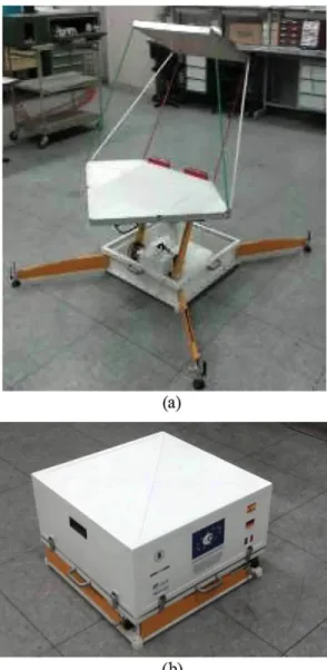
The aim of this work is to describe the main features of the proposed reconfigurable dual-reflector antenna and to prove the effectiveness of the design in order to electronically con-trol the radiation pattern. The paper is organized as follows. Section II describes the effects of the 1-bit phase discretiza-tion on the radiadiscretiza-tion pattern. Secdiscretiza-tion III describes the proposed dual-reflector antenna configuration: the main and subreflec-tor architecture, the feeding horn design, and the arrangement of the three elements. In Section IV, the principle of opera-tion and the structure of the elementary cell are described, and the effectiveness of the design is proved through experimental results. Section V reports the main aspects of the mechanical design of the antenna and the control circuit architecture. In Section VI, the experimental validation of the designed proto-type is reported: a full-reconfigurable demonstrator with 5250 elementary cells has been manufactured and tested (Fig. 1). Measured radiation patterns compared with the predicted ones are reported in order to validate the proposed design.
II. 1-BIT PHASE DISCRETIZATION
While conventional solutions for reconfigurable reflectarrays are based on elementary cells with a high number of states or
Fig. 1. Prototype of the designed reflectarray. (a) Operative configuration, (b) Stowed configuration.
based on analog control, a different approach is adopted in the proposed design.
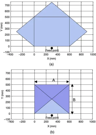
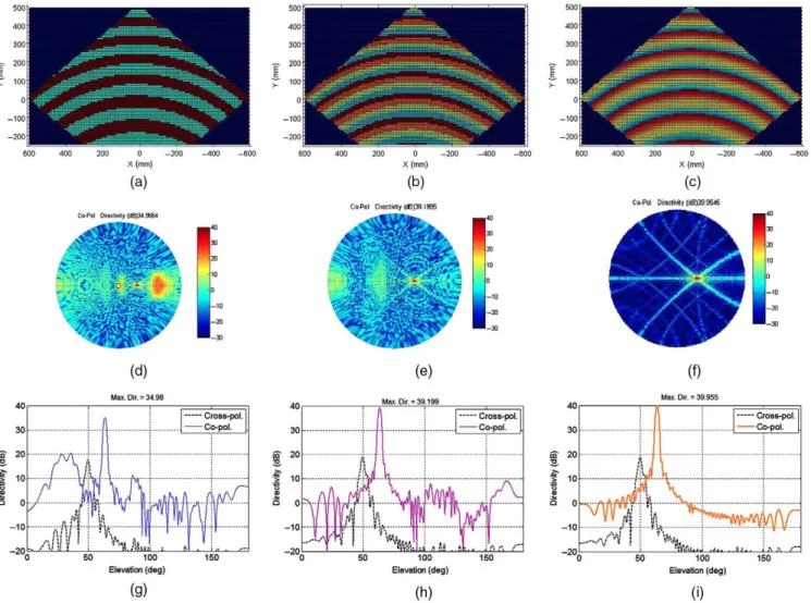
The need of a high antenna gain and low side-lobe level leads to a wide radiating aperture. Due to the large number of required elements, cost and complexity of the whole sys-tem become critical issues. A 1-bit phase resolution is therefore adopted. The feasibility of such a solution, investigated and assessed in [24] and [25], is shown through an example: aplanar reflectarray illuminated by a Gaussian feed pointed to the cen-tre of the antenna has been simulated. The dimensions of the reflectarray, reported in Fig. 2, are the same as the one devel-oped during the project. The radiation patterns (Fig. 3) show the behavior of the antenna at 12.75 GHz in case of a 1-bit, 2-bit, and 8-bit ideal phase discretization applied to the cells on the main reflector. The phase distribution is optimized to generate a collimated beam at 30° in elevation and 0° in azimuth (with respect to the normal direction of the planar reflector).
700
600
500
-g- 400
~" 300
200
100
0
-100 - 4 0 0
700
600
500
400
300
200
100
\
N
\:eetf poin t
-200 200 400
X(mm)
(a)
600 800 1000
A
reedpoin t
i
\
V
B
r
-100
- 4 0 0 - 2 0 0 200 400
X(mm)
(b)
600 800 1000
Fig. 2. Antenna configuration of the main reflector in (a) deployed and (b) stowed configuration.
results obtained with 2-bit and 8-bit phase shifters, a reduction of the antenna gain up to 5 dB can be observed, together with a small increase of the SLL. However, the main lobe-pointing direction and the beam-width remain unchanged in three cases. These properties have been achieved by properly selecting the feed position and reflectarray dimensions, after a parametric study.
III. ANTENNA GEOMETRY
The antenna proposed in this paper is a dual-reflectarray made up of three components: a primary feed, a passive rectan-gular subreflectarray, and a pentagonal active main reflectarray (Fig. 4) with 1-bit electronic control of the elementary cells. The antenna is designed to provide a directive beam with electronic scanning capabilities within a limited angular range (±5° with respect to a nominal direction) for both the Rx-(10.7-12.75 GHz) and Tx-bands (14-14.5 GHz).
A. Main Reflector Design
The aim of this work is the design and manufacturing of a reflectarray for broadband emergency communications, hence, a foldable antenna architecture allowing portability and size reduction is required. These aspects represent a remarkable lim-itation that has been overcome adopting a geometry of both the
main- and the subreflector based on a rectangular shape with dimensions A and B. The subreflector is a simple rectangular multilayer panel while the main reflector is a pentagon made up by an A x B rectangle and three "petals" that, in stowed configuration, are folded above the rectangle and in operative configuration are deployed as shown in Fig. 2.
In order to optimize the geometry of the antenna and, in particular, the size of A and B, an exhaustive analysis has been performed in terms of EIRP over RF transmit band and Gain [27]. The requirements are 32 dBi of antenna Gain and 32 dBW/40 kHz of maximum EIRP in the pointing direc-tion together with the accomplishment of the regulatory masks ETSI-EN.301.428 and ITU-R S.728.1. The analysis has been carried out considering a single-reflector antenna: a main reflec-tor with a 1-bit reconfigurable phase distribution and a dual-band and dual-polarization Gaussian feed pointed to the center of the reflector. The feed-relative position with respect to the center of the antenna (H, 6teed) has been optimized as well. The optimal main reflector conformed to the required value of EIRP and Gain is a pentagon build around a rectangle with size A = 50 cm and B = 60 cm. This reflectarray comprises 5250 elementary cells with lattice of 10 mm x 10 mm. The optimal feed position is defined by H = 300 cm and 6leed = 38°.
B. Subreflector Design
In order to reduce the dimensions and facilitate the folding and the transportation of the antenna, a dual-reflector configu-ration has been adopted. The subreflectarray has been designed considering an elliptical feed whose phase center is located at coordinates (300, 0, 30 mm) with respect to the reference sys-tem shown in Fig. 4. The feed is pointed toward the center of the subreflector.
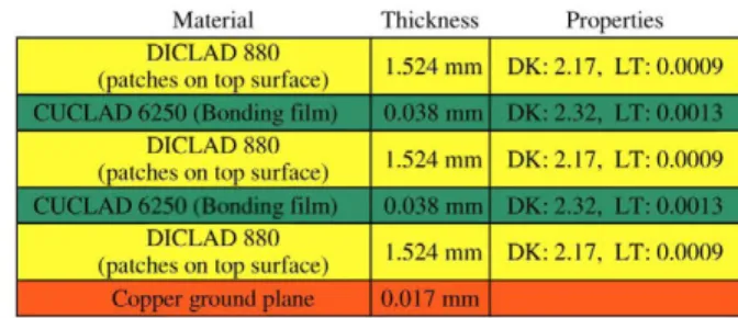
The optimization of the subreflector has been carried out in order to provide a phase and amplitude distribution of the field incident on the main reflector (both V- and H-pol.) equivalent to the distribution used for the optimization of the main reflec-tor. The analysis is performed using an in-house developed tool for the accurate modeling of dual-reflectarray antennas described in [28]. The resulting configuration of the subre-flector is an array of 38 x 48 elements with square lattice 12.5 mm x 12.5 mm (size: 475 mm x 600 mm) whose cen-ter is positioned at coordinates (—473 mm, 0 mm, 690 mm). The subreflector is inclined 27.5° with respect to the X-Y plane. As shown in Figs. 5 and 6, the subreflector is made of a three-layer printed array made of varying-sized stacked patches. The required phase shift of each element is achieved by properly optimizing the patch dimensions. The manufactured subreflector is depicted in Fig. 7.
C. Feed Horn
Co-Pol Directivity (dB)34.9664
50 100 Elevation (deg)
(g)
(f)
Max. Dir. = 39.955
Cross-pol. — Co-pol.
ft M
i\
X
k-Mk
\ |
I U <"'!! : h'>
^ I i
'*%
y ™k. "M
J a i l . si., iftrt / -100
Elevation (deg)
(h) (i)
Fig. 3. Effects of the phase discretization on the pattern produced by a planar reflectarray, illuminated by a Gaussian feed, with aperture described in Fig. 2(a). (a), (b), and (c) report the phase distribution on the planar reflector in case of 1-bit, 2-bits, and 8-bits phase discretization, respectively, (d), (e), and (f) show the 2-D polar plot of the antenna gain in the three cases, while (g), (h), and (i) report the elevation-cut of the same patterns.
The resulting horn model and a picture of the manufactured prototype are shown in Fig. 8.
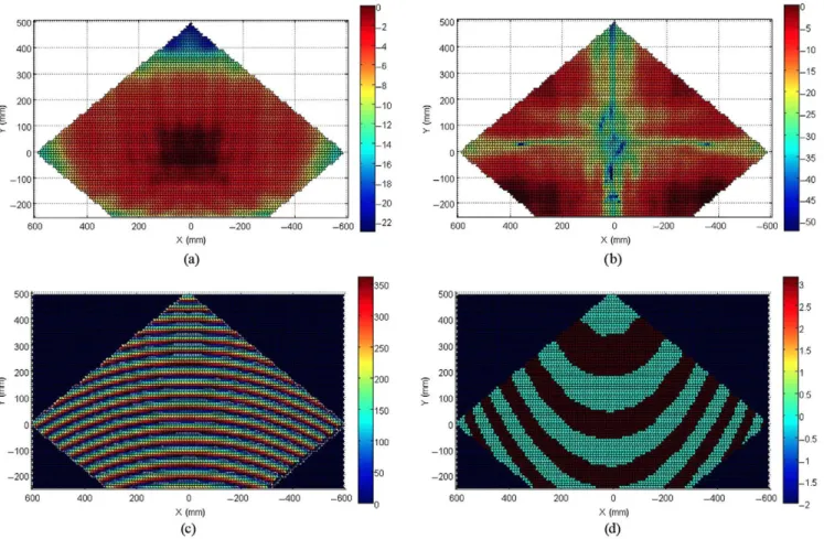
Fig. 9 shows the co- and cross-polarized field distribution on the main reflector at 12.75 GHz. The field is computed considering the effects of the designed feeding horn and the subreflector. The same figure reports also an example of 1-bit phase distribution on the main reflector, which corresponds to the beam pointed to 45° in elevation.
IV. RECONFIGURABLE REFLECTARRAY U N I T CELL In the proposed reflectarray, the reconfigurable unit cell is a PIN-diode-based element with large bandwidth (30% of rela-tive bandwidth), dual linear polarization, and 1 bit of relarela-tive phase shift.
The geometry of the proposed elementary cell is a stacked structure made up of six substrates bonded together with prepreg thin layers (Prepreg Arlon 47N). The substrate used for the RF parts is Arlon AD450 while the spacers are obtained by milled FR4 layers. Fig. 10 shows the exploded view of unit cell: a circular patch is printed on the top face of the upper substrate. On the lower substrate, the phase-shifting layer controls the
phase of the reflected signal by means of two PIN diodes and provides a ±90° rotation to the incident polarization. The patch is separated from the phase-shifting layer through a spacer milled on a FR4 substrate. Below the phase-shifting layer, another FR4 substrate separates the ground plane. The dc bias-ing of the PIN diodes is obtained through a via-hole connectbias-ing the phase-shifting layer to the FR4 biasing line layer. The via-hole goes through a small aperture realized on another FR4 thin layer which realizes the metal bottom of the cavity on one side and the RF-block on the other side [see Fig. 10(a) and (b)]. In order to minimize the mutual coupling between adjacent ele-ments in the lower spacer, a circular metallic cavity is realized by means of via-holes.
A. Principle of Operation of the Elementary Cell
300CK
2500.
2000.
1500.
1000.
500.
0 .
,*.-"" ¡
,-"•"" \
, , - i - - " " " !
' '* ¡
:-.-,.,
-I.
4
<::í^T
¿t>*'Éqúlvalefit feed póifrt. _
, ^ i I Sed
-500 "Fee
poiritx
Y (mm) _1 5 0 0
500 1000
-500 X (mm)
Fig. 4. Antenna configura! equivalent feed position for t
47.5 c m X 60 c m and ;. 3.
I
ILL
t t t
Fig. 5. Multilayer subreflector made of varying-sized patches, (a) Exploded view of the three-layer reflectarray. (b) Periodic cell.
Material Thickness Properties DICLAD 880
(patches on top surface) CUCLAD 6250 (Bonding film)
DICLAD 880 (patches on top surface)
DICLAD Í (patches on top surface)
Copper ground plane
1.524 mm
.524 mm
0.038 mm
1.524 mm
0.017 mm
DK:2.17, LT: 0.0009
DK: 2.32, LT: 0.0013
DK:2.17, LT: 0.0009
DK:2.32, LT: 0.0013
DK: 2.17, LT: 0.0009
—r—-After
-p a l b a s | £•
Zmm Í W
Fig. 7. Manufactured subreflector mounted on the final prototype.
(a) (b)
Fig. 6. Sandwich definition for a three-layer subreflector.
Fig. 8. Feeding horn: (a) side view; (b) front view; and (c) picture of the manufactured horn mounted on the final prototype.
500
300 200
E E ~ 100
0 -100
H | k |
¡ É t i "
¡É&-• ^
I
0 - 2 0 0 X (mm)
(c)
Fig. 9. Simulated amplitude of the incident field on the main reflector at 12.75 GHz. (a) Amplitude of the V-pol. (Co-pol.). (b) Amplitude of the H-pol. (Cross-pol.). (c) Phase of the V-pol. (Co-pol). (d) Example of 1-bit phase distribution on the main reflector (pointing direction 45° elevation, 0° azimuth).
coupled to one of the two possible active slot-line paths (third resonator) enclosed in the ring. By alternatively activating the PIN diodes, one of the two possible paths enclosed in the ring is selected. Correspondingly, the reflected field is subjected to +90° or —90° geometrical rotation. In other words, as shown in [21], the reflected field is orthogonally polarized with respect to the incident field, and the two states produce 180° of phase shift independent of the frequency.
B. Unit Cell Control and Model of the PIN Diode
Given the high number of devices required for the antenna assembly (10 500 diodes), the diode selection is the result of a trade-off between cost and performance. In this phase of development of a proof-of-concept project, the design of the elementary cell has been carried out adopting a low-cost pack-aged PIN diode (Skyworks DSG-9500). However, this device inevitably affects the efficiency of the antenna due to the high-series resistance (Rs) and the parasitic effects of the package. A future development of the design could easily overcome this issue by using bare-die (or unpackaged) PIN diodes. This solu-tion makes possible to increase the overall performance of the antenna and drastically reduce (up to a factor of ten) the unitary cost for the reconfigurable devices in a high volume production. In the proposed unit cell, the diodes are mounted in antipar-allel configuration, thus, depending on their state, they ideally act as a short-circuit or as an "RF-transparent" component on
the slot line. The antiparallel configuration allows the diodes to be alternatively activated with a single control signal with two opposite voltage values ±V. In this way, they are able to activate only one of the two possible paths on the slot line.
According to Fig. 10, in order to activate the PIN diodes, it is necessary to provide the ground reference voltage to the quarter-circle pads enclosed in the slot-line ring and the control voltage to the half-circle pad. The bottom metal layer of AD450 has been designed in such a way as to provide the ground ref-erence to each pad by using via holes and thin microstrip lines. As already described, the biasing voltage is provided with a via-hole that connects the half-circle pad to an external ref-erence coming from the backside of the elementary cell. An RF-block isolates from the high-frequency signal to the lower printed layer.
The structure of the elementary cell has been optimized in order to minimize the copolarization reflection coefficients in the operative bandwidth. The optimization has been carried out including the cell in the characterized model of the PIN diode. The circuit model of the diode has been derived experimentally by performing calibrated measurements. The RLC circuit mod-els of the PIN diode in ON- and OFF-state are detailed in Table I and Fig. 12. The ON-state model of the PIN diode is obtained by forward biasing it with a current of 72 mA and a voltage of + 5 V .
Arlon AD450 Circular patch
FR4 Spacer
Arlon AD450
Phase Shifting
Layer
FR4 Spacer
FR4 Ground
Plane
FR4 Biasing
Line
(a)
Circular patch Slot-line ring Slot-line resonator
Fig. 10. Exploded view of the proposed elementary cell: (a) top view; (b) bot-tom view, (c) Top and (d) botbot-tom view of the phase-shifting layer, (e) Magnified view of the pin diode switch. The dielectric constants, loss tangent, and thickness of the materials used are Arlon AD450 (er = 4.5, t a n a = 0.0035, h = 0.508 m m ) a n d FR4 (er = 4.4, t a n a = 0.02, / j = 2 m m and h = 256 m m ) .
periodic boundary conditions in combination with integrated lumped elements whose values are fixed in accordance with the extracted circuit model of the diode. The simulated co-and cross-polarization reflection coefficients are represented in Fig. 13(b), superimposed to the measurements. Since the elementary cell is designed in order to rotate the incident field polarization, to characterize its performance, the reflection
Fig. 11. Equivalent circuit of the proposed elementary cell.
TABLE I
CIRCUIT MODEL OF THE LUMPED COMPONENTS
RS(Q) L(nH)
CT (pF)
ON-STATE
8.2 0.012
PIN-DIODE STATE
OFF-STATE
0.012 0.027
ON OFF
Fig. 12. RLC circuit models of the PIN diode in ON- and OFF-state.
coefficients relevant to the cross- and copolarizations are used. Simulated loss of the elementary cell shows an average value of 4 dB. The HFSS model of the cell has been used in order to evaluate the effects on the loss of the device adopted. The anal-ysis highlights that an high performance PIN diode with a series resistance in the ON-state of Rs = 3 Q, instead of the currently adopted with Rs = 8 Cl, would reduce the loss of 1.8 dB.
Fig. 14 depicts the simulated phase of cross-polarization reflection coefficients in both configurations: it is worth to observe that the proposed architecture allows to obtain a rela-tive phase shift with an average level of 181.5° and a maximum deviation of 2°.
C. Unit Cell Prototyping and Measurement
-30
i. -50
e n CD
| -60
CO CO
» -7 0
-80 -90
i . i
1 1
1 1
i '
i 1 i |
•Co-pol. Metal Pjate Co-pol. AUT ¡ Cross-pol. AUT¡_
} 1 0 11 1
i i i i
• Z
l M.
2 1
1 i i i i
' i A
A '
3 14 15 16 1 Frequency (GHz)
(a)
- 4 0
•Co-pol. Simulated •Cross-pol. Simulated -Co-pol. Measured -Co-pol. Measufed
8 9 10 11 12 13 14 15 16 17 Frequency (GHz)
(b)
Fig. 13. Measured co- and cross-polarization reflection coefficients of the elementary cell compared to the measurements of a (a) reference metal plate and (b) with simulations, (c) Front and (d) back view of the measured array, (e) Pictures of elementary cells manufactured for the tests.
Fig. 14. Measured phase shift between the cross-polarization reflection coeffi-cients of the cell in both the possible states.
its normal direction. In order to analyze both the co- and cross-polarization reflection coefficients, the receiving horn can be twisted around the axis of the radiating direction by 0° or 90°.
Compared to the waveguide simulator measurement setup (WGS), this solution requires the manufacturing of a larger breadboard prototype, but also provides some advantages. In fact, the response of the cell can be evaluated with an arbi-trary selected incidence angle also varying the frequency, while in the WGS for a fixed width of the waveguide, the incidence angle varies depending on the frequency. Moreover in a free-space reflection setup, the periodicity of the elementary cell is
(b) (c)
(f)
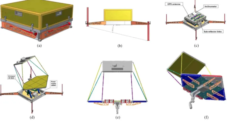
Fig. 15. (a) Antenna in transportation configuration, (b) Stabilizing feet of the antenna, (c) Stowed configuration of the antenna components, (d)-(f) Deployed configuration from different points of view.
the planarity of the copper plate, can affect the specular direc-tion in which the signal is reflected leading to a variable level of the copolarization reflection coefficients of the copper plate.
V. MECHANICAL DESIGN AND ELECTRONIC CONTROL OF THE ANTENNA
In the previous sections, the features relevant to the RF design of the antenna have been analyzed. In the following, a description of the mechanical and electrical solution adopted for the design of the antenna and the control of the main reflector configuration will be provided.
A. Mechanical Design of the Antenna
One of the key objectives of the project is the development of a foldable and portable reflectarray antenna. As already shown, a proper architecture has been therefore proposed for this pur-pose. The antenna is conceived in such a way as to present a rectangular shape in stowed position and a trapezoidal shape when deployed, obtained by unfolding of three triangular pan-els ("petals"). The feed is placed in the edge where the forth petal is missing. In stowed position, the subreflector is stored directly above the folded main reflector while the feed is housed below the main reflector.
Due to these folding properties, the RF part can be com-pacted and the whole antenna can be enclosed in a box
[Fig. 15(a)]. During the deployment, the subreflector is man-ually linked to the main reflector using six supporting links. An elevation mechanism allows the main reflector to be manually pointed with an inclination from +26° to —34° with respect
to the horizontal position. Azimuth rotation is also performed mechanically in the range of 360°. This allows the user to perform a first rough pointing of the antenna, assisted by on-board sensors (GPS, compass, etc). Once the antenna is roughly pointed, the electronic beam steering can automatically point the satellite direction. The antenna in operative configuration is shown in Fig. 15(d).
In order to dissipate the heat produced on the electrical equipment integrated with the antenna main reflector, a cool-ing system has been studied in detail: four fans positioned on the same level of the feeding horn push a continuous air stream on the lower surface of the antenna board. All the mechanical parts of the antenna have been designed to make it resistant to the stress provided by the wind force. The design has been performed considering a wind speed of 80 km/h and consider-ing the antenna in the worst condition in terms of mechanical inclination.
B. Control Board
(c)
Fig. 16. Control board of the antenna during the assembly: (a) the logical subdi-vision in triangle of the main reflectarray can be observed, (b) Control circuitry general architecture, (c) Triangular control circuit board.
All the components of the control logic have to fit in a small triangular area, whereas some spaces need to be empty for mechanical purposes. The solution adopted is based on a mul-tilayer Panel Control Board (PCB), which provides the routing of the biasing line of 375 cells by means of 48 cascaded shift registers.
The 14 PCB modules are programmed and controlled by a RS232 Interface Board [Fig. 16(b)] equipped with a micro-controller which translates an incoming serial data stream in the correct signal sequence and distributes it to the panels [Fig. 16(c)]. An external high-level application is used to drive the microcontroller, and hence, to provide the desired state to all the elementary cells of the reflectarray.
VI. MANUFACTURING AND T E S T
The antenna, including the RF circuits, the control boards, and the supporting mechanics, has been manufactured and
assembled by Elital srl (L'Aquila, Italy). The prototype has been measured in the anechoic chamber of the Testing and Certification Antenna Laboratory (LEHA) of the UPM (Madrid, Spain).
During the measurements, the antenna was controlled by a PC connected through a serial port to the electronic con-trol board of the antenna. The PC synthesizes the correct state for the main reflector first by calculating the ideal phase distribution then by applying the 1-bit quantization.
To verify the beam-scanning operation mode, the synthe-sis algorithm is applied to obtain the main beam pointed to some specific directions in the elevation plane of the antenna.
For each scanning angle, the measurements of the azimuth and elevation cuts of the dual-refiectarray antenna for vertical and horizontal polarizations at different frequencies have been carried out. The selected frequencies cover the typical transmit and receive frequency bands of the Ku-band satellite communi-cations. Since in operative conditions, the electronic steering of the main lobe is used to refine the pointing direction of the antenna, the scanning angles have been first observed in a limited range (±5° in azimuth and elevation) with respect to a nominal pointing direction selected (45° elevation, 0C
azimuth).
Fig. 17 shows the radiation patterns measured by varying the frequency and the pointing angle in elevation from 40° to 50° with a step of 5°. The measured patterns refer to the V-pol. for the frequency of 11.5-12.75 GHz and to the H-pol. for the frequency of 14.25 GHz.
For each configuration, the antenna measured at the fre-quency of synthesis (12.75 GHz) provides a precise pointing of the main lobe in the desired direction. Changing the fre-quency of analysis, gain variations lesser than 2.6 dB can be observed. Measurements highlight that the pointing direc-tion of the antenna is subjected to the effect of frequency squint. Considering the worst case (elevation 50° and azimuth 0°), the frequency variation "moves" the main-lobe direction with respect to the nominal pointing of ±2°. In Fig. 18(e), the levels of cross-polarization in case of elevation 45° and azimuth 0° can be observed varying the operative frequency. The cross-polarization in the pointing direction is always below - 1 8 dB (also in the configurations not reported in this paper).
80 100 Angle (deg)
(a)
80 100 Angle (deg)
(C) 25
2, 5
¿3 °
- 2 0
A
i
á—
j f \ / i .
11.5GHzV-pol. 14.25GHz H-pol
A l
• ™ Ifl
i . i .
TUB
1
lira i»
• a n j B B i
80 100 Angle (deg)
(e)
2b 20
10 5 0 -5 -10 -15 -?n
1 1 "
11.5GHz V-pol. 14.25GHz H-pol.
r m -—
25 20 15 10
i
5I °
- 5
- 1 0
- 1 5
- 2 0
-20 0 20 Angle (deg)
(b)
Ir ¡I
11.5GHzV-pol. 14.25GHz H-pol.
-20 0 20 Angle (deg)
(d)
25 20
10 •0 5
c a 0
a
- 5 - 1 0 -15
- 2 0 Jlr.i-1
11.5GHz V-pol. 14.25GHz H-pol.
- 4 0 - 2 0 0 20 Angle (deg)
(f)
40
Fig. 17. Measured radiation pattern of the antenna for different pointing direction in elevation (azimuth is 0°): (a) elevation and (b) azimuth cuts for pointing direction 50°; (c) elevation and (d) azimuth cuts for pointing direction 45°; (e) elevation and (f) azimuth cuts for pointing direction 40°.
as well as the antenna in the Gregorian compact range test chamber.
The measured radiation patterns are similar with respect to the simulated ones except for the gain value. Even if the antenna is able to point the main lobe with a very good accuracy, the obtained gain values reveal a low antenna efficiency.
The low efficiency is caused by a number of reasons. First of all, the nature of the adopted PIN diode: the high series resistance Rs of the diode and the parasitic effects of the pack-age provide 4 dB of loss. Moreover, this limitation is further enhanced by a second relevant factor: the need to limit the
power consumption of the antenna. In fact, the aim of the antenna is to be a portable system for emergency communi-cations, and this constrained the biasing current of the PIN diodes from 72 mA used during the test of the single element to 20 mA. The consequent additive loss provided by this factor is 2.1 dB. This value has been estimated using an updated model of the diode, experimentally derived from calibrated measure-ments, in combination with the HFSS model of the elementary cell.
/ \
J\
ill*
m
A
H
/h
J "
w
AÍ>
M
ill
P 1
M
1AU
Vw
i M .P
tts
Jp
Measured V-pol. 12.75GHz
— Simulated V-pol. 12.75GHz
r*U
m
Jejuni
A
to
n
/i/M
A/U
M
ftF
i
J
Í
ÍI
hi*
80 100Angle (deg)
(a)
zr
- j
^ d P i
4?JM
W
i
P0L
r
y
\
\ \
! ^
p
i
Measured V-pol. 12.75GHz Simulated V-pol. 12.75GHz
l
P\
AH/IA
CTUL
M l
in
, / *
¡/
ñ .i
iiii
80 100 Angle (deg)
(C)
180
~ £
—/
3C
71'
Tfl
4£
H t
BBC
P T
la
f
>i
Measured V-pol. 12.75GHz Simulated V-pol. 12.75GHz
P HUfl
(IfW
fflilll ffiT
^ ~
JL
Vi
T i n ' I n i
80 100 Angle (deg)
(b)
V
m
V\
Li
A\
A
ri
J l
A
i
IN
fl 1.
lw
UUA
If
il
11
'An
M S
J
easured H-pol. 12.75GHz mulated H-pol. 12.75GHz
«J r»
_snrL
1
1
Wi
ilA
_
Fig. 18. Measured radiation patterns of the antenna compared with the simulated radiation patterns: V-polarization at 12.75 GHz with pointing direction (a) 50°; (b) 45°; and (c) 40°. (d) H-polarization at 12.75 GHz. (e) Comparison between the co- and cross-polarization levels for the configuration with pointing direction elevation = 45° and azimuth = 0°. (f) Manufactured prototype during the measurements.
gain reduction of roughly 2 dB. The high damage rate is due to the critical procedure of manual soldering of the PIN diodes. The effects of the damaged cells are highlighted also by the repolarization radiation pattern in Fig. 18(d): broken cells do not rotate the incident field, thus the measured level of the unde-sired polarization radiated is visibly higher with respect to the simulated one.
O 20 40 60 80 100 120 140 160 180 Angle (deg)
(a)
y
I
A.P
m
ii.Aimm
WW
j \
m
11
'i
i
l
jJfttAJ
m
V
JL.
V
r
ü
¥
É
!-80 -60 -40 -20 0 20 40 60 80 Angle (deg)
(C)
Fig. 19. Radiation pattern of the antenna evaluated for wider scanning angle, (a) Elevation is varied from 90° (broadside) up to 30° and azimuth is maintained 0°. (b) Elevation is 40° and azimuth is varied from 0° up to 15°.
VII. CONCLUSION
A dual reflectarray antenna with a compact optics has been proposed in this paper. The antenna is designed to provide electronic beam steering in portable systems for Ku-band satel-lite links with automatic pointing capabilities. The antenna configuration comprises a passive subreflectarray and a main reflectarray with 1-bit electronic control to provide a pencil beam steerable in a wide angular range.
The design of the reconfigurable elementary cell and the reflectarray architecture has been described along with the solution adopted for the deployability and the control of the elementary cells. The measured radiation patterns of the
full-reconfigurable manufactured prototype have experimen-tally validated the principle of operation of the proposed antenna.
The low efficiency of the prototype is the main limitation of the design and is mainly provided by the adopted low-performance PIN diode. Anyway, this issue can be overcome by the use of bare-die PIN diodes along with the automatic mount-ing. This kind of device allows the elementary cell performance to avoid the parasitic effects of the chip package thus obtaining, in future developments of the project, better performance with sensibly reduced costs.
REFERENCES
[1] C. Han, S. Hsu, K. Chang, and J. Huang, "A Ku/Ka-dual band reflectarray to emulate a cylindrical reflector for titan cloud precipitation radar and altimeter," in Proc. IEEE Antennas Propag. Soc. Int. Symp., Jun. 9-15, 2007, pp. 1445-1448.
[2] D. M. Pozar, S. D. Targonski, and R. Pokuls, "A shaped-beam microstrip patch reflectarray," IEEE Trans. Antennas Propag., vol. 47, no. 7, pp. 1167-1173, Jul. 1999.
[3] J. A. Encinar, M. Arrebola, and G. Toso, "A parabolic reflectarray for a bandwidth improved contoured beam coverage," in Proc. 2nd Eur. Conf.
Antennas Propag. (EuCAP'07), Nov. 11-16, 2007, pp. 1-5.
[4] J. Huang and J. Encinar, Reflectarray Antennas. Hoboken, NJ, USA: Wiley/IEEE Press, 2008.
[5] S. Hum, M. Okoniewski, and R. Davies, "Modeling and design of elec-tronically tunable reflectarrays," IEEE Trans. Antennas Propag., vol. 55, no. 8, pp. 2200-2210, Aug. 2007.
[6] L. Boccia, G. Amendola, and G. Di Massa, "Performance improve-ment for a varactor-loaded reflectarray eleimprove-ment," IEEE Trans. Antennas
Propag., vol. 58, no. 2, pp. 585-589, Feb. 2010.
[7] M. Riel and J.-J. Laurin, "Design of an electronically beam scanning reflectarray using aperture-coupled elements," IEEE Trans. Antennas
Propag., vol. 55, no. 5, pp. 1260-1266, May 2007.
[8] J. Perruisseau-Carrier, "Dual-polarized and polarization-flexible reflec-tive cells with dynamic phase control," IEEE Trans. Antennas Propag., vol. 58, no. 5, pp. 1494-1502, May 2010.
[9] D. Sievenpiper, J. Schaffner, H. Song, R. Loo, and G. Tangonan, "Two-dimensional beam steering using an electrically tunable impedance sur-face," IEEE Trans. Antennas Propag., vol. 51, no. 10, pp. 2713-2722, Oct. 2003.
[10] H. Kamoda, T. Iwasaki, J. Tsumochi, T. Kuki, and O. Hashimoto, "60-GHz electronically reconfigurable large reflectarray using single-bit phase shifters," IEEE Trans. Antennas Propag., vol. 59, no. 7, pp. 2524-2531, Jul. 2011.
[11] R. Pereira et al., "Robust 2-bit dual-linearly-polarised unit-cell for reflec-tarray applications," in Proc. 5th Eur. Conf. Antennas Propag. (EUCAP), Apr. 2011, pp. 1488-1490.
[12] N. Martin, P. Laurent, C. Person, P. Gelin, and F. Huret, "Patch antenna adjustable in frequency using liquid crystal," in Proc. 33rd Eur. Microw.
Conf., Oct. 2003, vol. 2, pp. 699-702.
[13] R. Cahill et al., "Recent progress in electronically tunable reflectar-ray technologyusing liquid crystals," in Proc. 5th Eur. Conf. Antennas
Propag. (EUCAP), Apr. 2011, pp. 2866-2870.
[14] S. Dieter, P. Feil, and W. Menzel, "Folded reflectarray antenna using a modifiedpolarization grid for beam-steering," in Proc. 5th Eur. Conf.
Antennas Propag. (EUCAP), Apr. 2011, pp. 1400-1403.
[15] A. Moessinger, R. Marin, S. Mueller, J. Freese, and R. Jakoby, "Electronicallyreconfigurable reflectarrays with nematic liquid crystals,"
Electron. Lett., vol. 42, no. 16, pp. 899-900, 2006.
[16] S. V. Hum, G. McFeetors, and M. Okoniewski, "Integrated MEMS reflec-tarray elements," in Proc. 1st Eur. Conf. Antennas Propag. (EuCAP'06), Nov. 2006, pp. 1-6.
[17] E. Perret, H. Aubert, and H. Legay, "Scale-changing technique for the electromagnetic modeling of MEMS-controlled planar phase shifters,"
IEEE Trans. Microw. Theory Tech., vol. 54, no. 9, pp. 3594-3601, Sep.
2006.
[18] H. Legay et al., "A steerable reflectarray antenna with MEMS con-trols," in Proc. IEEE Int. Symp. Phased Array Syst. Technol, Oct. 2003, pp. 494^199.
[19] H. Rajagopalan, Y. Rahmat-Samii, and W. Imbriale, "RfMEMS actuated reconfigurable reflectarray patch-slot element," IEEE Trans. Antennas
[20] C.-C. Cheng and A. Abbaspour-Tamijani, "Evaluation of a novel topol-ogy for MEMS programmable reflectarray antennas," IEEE Trans.
Microw. Theory Tech., vol. 57, no. 12, pp. 3333-3344, Dec. 2009.
[21] E. Carrasco, M. Barba, and J. A. Encinar, "X-band reflectarray antenna with switching-beam using PIN diodes and gathered elements," IEEE
Trans. Antennas Propag., vol. 60, no. 12, pp. 5700-5708, Dec. 2012.
[22] ETSI EN 301 428 VI.3.1. Satellite Earth Stations and Systems
(SES); Harmonized EN for Very Small Aperture Terminal (VSAT)
[Online]. Available: http://www.etsi.org/deliver/etsi_en/301400_301499/
301428/01.03.01_60/en_301428v010301p.pdf
[23] ITU-R S.728.1. "Maximum permissible levels of off-axis E.I.R.P density from VSAT" [Online]. Available: https://www.itu.int/dms_pubrec/itu-r/rec/s/R-REC-S.728-1 -199510-1! IPDF-E.pdf
[24] B. Wu, A. Sutinjo, M. E. Potter, and M. Okoniewski, "On the selection of the number of bits to control a dynamic digital MEMS reflectarray,"
IEEE Antennas Wireless Propag. Lett., vol. 7, pp. 183-186, Mar. 2008.
[25] S. Ebadi, R. V Gatti, and R. Sorrentino, "Linear reflectarray antenna design using 1-bit digital phase shifters," in Proc. 3rd Eur. Conf. Antennas
Propag. (EuCAP'09), Berlin, Germany, Mar. 2009, pp. 3729-3732.
[26] S. Montori et al., "Wideband dual-polarization reconfigurable elementary cell for electronic steerable reflectarray at Ku-band," in Proc. 4th Eur.
Conf. Antennas Propag. (EuCAP), Apr. 12-16, 2010, pp. 1-5.
[27] H. El Gannudi, R. V Gatti, C. Tomassoni, and R. Sorrentino, "Preliminary design of foldable reconfigurable reflectarray for Ku-band satellite com-munication," in Proc. 4th Eur. Conf. Antennas Propag. (EuCAP), Apr. 12-16, 2010, pp. 1-5.
[28] C. Tienda et al., "Dual-reflectarray antenna for bidirectional satellite links in Ku-band," in Proc. 5th Eur. Conf. Antennas Propag. (EUCAP), Apr. 11-15, 2011, pp. 1404-1407.
Simone Montori received the Laurea degree (with
distinction) in electronic engineering and the Ph.D. degree from the University of Perugia, Perugia, Italy, in 2006 and 2012, respectively.
In 2006, he joined the Department of Electronic and Information Engineering (DIEI), University of Perugia, as a Research Assistant in Reconfigurable Antenna Systems. He is currently working at RF Microtech srl, Perugia, Italy, as RF and microwave R&D Engineer.
Fabrizio Cacciamani received the Master Laurea
degree in electronic engineering from the University of Perugia, Perugia, Italy, in 2009.
In February 2010, he joined the Department of Electronic and Information Engineering (DIEI), University of Perugia. For the last two years, he has collaborated with RF Microtech (spin-off of Perugia University, Italy) in several international research projects concerning RF MEMS, microwave filter, and antenna design.
Roberto Sorrentino (M'77-SM'84-F'90) received
the Doctor degree in electronic engineering from the University of Rome "La Sapienza," Rome, Italy, in 1971.
, .. F In 1974, he became an Assistant Professor \v'."•'• ' °f Microwaves with the University of Rome "LaSapienza." He was an Adjunct Professor with the University of Catania, the University of Ancona, and ^ ^ the University of Rome "La Sapienza" (1977-1982), ?w\ I T where he then was an Associate Professor from 1982 to 1986. In 1983 and 1986, he was a Research Fellow with the University of Texas at Austin, Austin, TX, USA. From 1986 to 1990, he was a Professor with the University of Rome "Tor Vergata." Since November 1990, he has been a Professor with the University of Perugia, Perugia, Italy, where he was the Chairman of the Electronic Department, Director of the Computer Center (1990-1995), and Dean of the Faculty of Engineering (1995-2001). In 2007, he founded RF Microtech srl, Perugia, Italy (a spinoff of the University of Perugia). In 1998, he was one of the Founders of the European Microwave Association (EuMA) and was its President from its constitution until 2009. In 2002, he was among the Founders and First President of the Italian Electromagnetic Society (SIEm), which he chaired until 2008. From 1998 to 2005, he was a Member of the High Technical Council, Italian Ministry of Communications.
Dr. Sorrentino was the Editor-in-Chief of the IEEE MICROWAVE AND GUIDED WAVE LETTERS, from January 1995 to April 1998. From 1998 to 2005, he was on the Administrative Committee of the IEEE Microwave Theory and Techniques Society (IEEE MTT-S). He is a member of Technical Committees MTT-15 on Field Theory and MTT-1 on Computer-Aided Design. He was the recipient of the IEEE MTT-S Meritorious Service Award in 1993, and one of the recipients of the IEEE Third Millennium Medal in 2000, and the recipient of the Distinguished Educator Award of the IEEE MTT-S in 2004.
Guido Arista received the Diploma degree in
elec-tronics and telecommunications from the ITIS "A. di Savoia Duca d'Aosta" of L'Aquila, Italy, 1996.
He currently is the General Manager in Elital srl, L'Aquila, Italy, for the technical design, production activities, and commercial affairs from negotiation to post-delivery phase. His skills and past experience are: electronics and mechanical engineering, printed circuits manufacturing, and certification for space
Roberto Vincenti Gatti received the Laurea degree
(summa cum laude) and the Ph.D. degree from the
University of Perugia, Perugia, Italy, in 2000 and 2007, respectively.
Since 2007, he has been a Research Assistant with the University of Perugia. From September 2007 to March 2012, he was the Vice President of RF Microtech srl.
Dr. Gatti is serving as Reviewer of numerous tech-nical journals such as the IEEE TRANSACTIONS ON
MICROWAVE THEORY AND TECHNIQUES (T-MTT),
Electronics Letters (IET Journals), and International Journal of Microwave and Wireless Technologies. Since 2009, he has been a member of the IEEE
International Microwave Symposium Technical Program Review Committee.
Carolina Tienda received the Degree in
telecommu-nication engineering from the Universidad de Málaga (UMA), Málaga, Spain, in 2005, and the Ph.D. degree in telecommunication from the Universidad Politécnica de Madrid (UPM), Spain, in 2012.
dvÉ
José A. Encinar (S'81-M'86-SM'09-F'10) was
born in Madrid, Spain. He received the Electrical Engineer and the Ph.D. degrees from the Universidad Politécnica de Madrid (UPM), Madrid, Spain, in 1979 and 1985, respectively.
Since January 1980, he has been with the Applied Electromagnetism and Microwaves Group, UPM, as a Teaching and Research Assistant from 1980 to 1982, as an Assistant Professor from 1983 to
1986, and as Associate Professor from 1986 to 1991. From February to October of 1987, he was a Postdoctoral Fellow of the NATO Science Program with the Polytechnic University, Brooklyn, NY, USA. Since 1991, he has been a Professor of the Electromagnetism and Circuit Theory Department, UPM. He was a Visiting Professor with the Laboratory of Electromagnetics and Acoustics, Ecole Polytechnique Fedérale de Lausanne (EPFL), Lausanne, Switzerland, in 1996, and with the Institute of Electronics, Communication, and Information Technology (EOT), Queen's University Belfast, Belfast, U.K., in 2006 and 2011. He has authored more than 150 journal and conference papers, and he is holder of five patents on array and reflectarray antennas. His research interests include numerical techniques for the analysis of multilayer periodic structures, design of frequency-selective surfaces, printed arrays, and reflectarrays.
Dr. Encinar has been a member of the Technical Programme Committee of several international conferences (the European Conference on Antennas and Propagation, ESA Antenna Workshops, and the Loughborough Antennas and Propagation Conference). He was a corecipient of the 2005 H. A. Wheeler Applications Prize Paper Award and the 2007 S. A. Schelkunoff Transactions Prize Paper Award, given by the IEEE Antennas and Propagation Society.
Giovanni Toso (S'93-M'00-SM'07) received the
Laurea degree (summa cum laude) and the Ph.D. degree in electrical engineering from the University of Florence, Florence, Italy, in 1992 and 1995, respec-tively.
In 1996, he was a Visiting Scientist at the Laboratoire d'Optique Electromagnétique, Univer-sity of Aix-Marseille III, Marseille, France. From 1997 to 1999, he was a Postdoctoral Student at the University of Florence, Firenze, Italy. In 1999, he was a Visiting Scientist at the University of California, Los Angeles (UCLA), CA, USA. In the same year, he received a scholarship from Thales Alenia Space (Rome, Italy) and was appointed Researcher with the Radioastronomy Observatory of the Italian National Council of Researches (CNR). Since 2000, he has been with the Antenna and Submiilimeter Section, European Space and Technology Centre, European Space Agency, ESA ESTEC, Noordwijk, The Netherlands. He has been initiating and contributing to several R&D activities on satellite antennas based on arrays, reflectarrays, constrained lenses and reflectors. He has coauthored more than 50 technical papers published in peer-reviewed professional journals, more than 200 papers published in international conference proceedings, and more than 10 interna-tional patents. In 2009, he was the Co-Editor of the Special Issue on Active Antennas for Satellite Applications in the International Journal of Antennas
and Propagation.
Dr. Toso has been the Co-Guest Editor of the Special Issue on Innovative Phased Array Antennas Based on Non-Regular Lattices and Overlapped Subarrays published in the IEEE TRANSACTIONS ON ANTENNAS AND PROPAGATION in April 2014. He is an Associate Editor of the IEEE