Integrating Measured Force Feedback in
Passive Multilateral Teleoperation.
Michael Panzirsch, Thomas Hulin, Jordi Artigas, Christian Ott, Manuel Ferre
Abstract. In teleoperation systems, the master robot receives force feedback from the remote slave side. Thus, the human operator can per- ceive the contact between the slave robot and its environment. Appli- cation of a force sensor at the slave robot improves the performance of the telepresence system in terms of transparency. Still, so far no approach allowing measured force feedback in time delayed multilateral systems that allow the interaction of multiple agents can be found in lit- erature. To this end, this paper presents a multilateral setup with passive measured force feedback based on the time domain passivity approach. Besides this solution to measured force feedback in multilateral systems, the presented approach promises improvements compared to other time invariant and model based approaches for measured force feedback also when applied to bilateral systems. Experiments are presented to allow for a performance analysis of the proposed system design.
Keywords: teleoperation, m easured force feedback, p assivity, TDPA
1 Introduction
The enhancement of robot technology in the past few years increased the quality of teleoperation systems that couple a slave robot with a master input device by a controller. Besides former application in space and the nuclear industry, new markets, e.g. in medicine and industrial maintenance evolved. Impedance controlled light weight robots, higher computational performance and modern control techniques improved the transparency of teleoperation systems, i.e. the quality of immersion into the slave’s environment that the human operator per- ceives via his/her interaction device.
to master through the communication channel [3,4,7]. Measured force feedback eases the remote control of the slave’s motion in free environment as the slave robot’s dynamics are completely masked and only the interaction force with the environment is perceived by the operator. Furthermore, forces of higher
bandwidth are transmitted in theP Fmeasarchitecture compared to the
Position-Force computed (P Fcomp) architecture. In this type of architecture the force of
the PI controller is fed back to the master which can have a damping effect
during free motion, i.e. transparency is reduced. Tavakoli et al. studied in [12]
the benefits of a 4-Channel architecture that consists of two controllers on each side of the communication channel and feedback of the measured human and environmental interaction forces. In theory, a perfectly transparent system can be achieved through this architecture.
The motivation of this paper originates from multilateral systems that are
currently of high interest for training and cooperative scenarios [10]. In
partic-ular, multilateral control approaches that consider time delay are based on the
principle of passivity. Willaert et al. [14] showed that bilateral control structures
which contain force sensors are non-passive. Passivity could be established by representing the system created by the slave robot and the environment through a 1-port network. However, in that approach, the force feedback path is
consid-erably downscaled and a maximmal environment impedance is assumed. In [6],
Khademian et al. designed a 4-Channel system for multilateral control. In [8],
the Raisbeck passivity criterion was applied. Kanno and Yokokohji [5], Quang
and Ryu [11] and Panzirsch et al. [9] presented multilateral teleoperation systems
considering time delay. The passivity of the communication channels were guar-anteed by the wave variables method and the time domain passivity approach
(TDPA) respectively. In [9], a generic approach based on passive modules was
developed which serve as the basic multilateral framework for the present work.
In [2], Artigas et al. applied the TDPA in order to handle the effect of time
delay in a bilateralP Fmeasarchitecture by representing the system through time
domain passivity networks (TDPN). Tobergte and Albu-Schaeffer [13]
imple-mented a full state feedback controller for bilateral teleoperation of a surgical robot. The approach allowed stable interaction with hard and soft environments. The TDPA guaranteed passivity of the overall bilateral teleoperator. In contrast
to the present work [2,13] applied the TDPA to the time delay in the
communi-cation channel.
Section2provides an overview of our modular multilateral architecture [9] and the related challenges of measured force feedback. The model-free control app-roach for measured force feedback architectures as the main contribution of the
paper is presented in Sect.3. Experiments are presented in Sect.4 and Sect.5
summarizes the results.
2
Multilateral Structure
+ - +
+
-vm vmdel vs
FE
Fdel
E FP I
Fh
Human M aster Ctrl Slave Env
e−T1s
e−T2s
Fig. 1.Signal flow for measured force feedback architecture
The signal flow
diagram of a 1DoF (Degree of Freedom)
bilateralP Fmeas
archi-tecture is depicted in
Fig.1. The human
operator is controlling a slave robot in a remote or
unaccessi-ble environment (Env)
through a master input device. The slave’s position is controlled by a
posi-tion/velocity controller (Ctrl) - acting as a virtual spring - to match the master’s
position. The measured interaction force between slave and environment is fed back to the master. The communication channel is represented by the Laplace
transformation of a pure constant delaye−T1sande−T2s. A virtual damping can
be added as a proportional part in the controller (Ctrl) or as local dampers at
master and slave devices.
Anderson proposed in [1] the application of the network representation to the
analysis of teleoperation systems. The network representation divides a system into several n-ports that are connected by power-conjugated ports. Port i is an interface of flow vi and effort Fi such that a power Pi(t) = Fi(t)vi(t) can be
defined at port i.
Figure2shows an exemplary network representation of aP Fmeasarchitecture
without time delay. The generalized multilateral system developed in [9] can be
analyzed in Fig.3. The human operator at the master and the slave in its
envi-ronment are represented as agent subsystems conjointly. Those are connected
+ −
+
− +
− +
− +
− +
− +
− F0
FE vH
FH
vP I
FP I vM
vM FM
vE
FE vM
FP I
Agent1 T rack Agent2
Ze Zh
ZP I Zs Zm
Human M aster Ctrl Env
Fig. 2. Network representation of a
P Fcomp architecture without time
delay
+
+
+
+ +
+
+ +
+
Agent
1 Agent
2
Agent3
PC
U PC
U
P CU T rack1
T ra
ck2 Track
3
via power control units (PCU) and tracks containing e.g. controller and
commu-nication channel. Figure4 presents the bilateral network representation for the
1-port passivity approach presented in [14]. This approach for passive measured
force feedback cannot be straightforwardly applied to multilateral systems as no 1-port teleoperation subsystem integrating the devices, controllers and the environment can be defined for the multilateral network. This problem is the main motivation for the present work.
3
Control Design
+
-+
-+
-vH
FH
vM
FM
vE
FE
Human M aster Ctrl and Slave Env
1-port teleoperator
Fig. 4. Network representation of the 1-port teleoperator proposed in [14]
Another approach has to be inves-tigated for multilateral systems with measured force feedback. The
TDPA for a passiveP Fmeas
mod-ule is suggested as a solution and
designed in the following. Figure5
can be considered as a generaliza-tion of a bilateral 2-channel tele-operation system (the subsystems
P CL/Rhave to be neglected first).
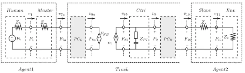
The setup is split up into two channels representing the two directions of energy
flow (compare [2]). Energy sent from master to slave is flowing from left to right
(L2R) and the energy sent from slave to master flows in right to left (R2L)
direc-tion. In R2L direction a dependent effort source FF B injects energy that is sent
from slave to master. The dependent flow sourcev1injects the energy introduced
by the master in L2R direction. The power flowing in the R2L part of the track in direction to the slave is dissipated by the effort source and the power flowing in direction to the flow source in the L2R part of track is dissipated by the flow source. The power at the ports flowing in the different directions can be easily distinguished:
P8Lb2R(t) =
0, ifP8b(t)<0
P8b(t),ifP8b(t)>0 and P
R2L
8b (t) =
0, ifP8b(t)>0 −P8b(t),ifP8b(t)<0
with P8b(t) = v8b(t)F8b(t). The same computation of power flow holds for all
other ports.
In the case of open loop teleoperation where the master receives no feedback
the dependent effort source does not inject energy, asFF B is zero. The system
is stable, as the L2R can be proven to be passive. The PI-controller acting as spring and damper is passive and the terminations (i.e. the environment, human operator and their representative effort and flow source) are generally assumed to behave passive in their interactions.
In aP Fcomparchitecture (compare Fig.2)FF Bis equal toF8b. Every network
+
−
+ −
+
− +
− +
−
+
−
+
−
+ −
+
− P CR P CL
FF B v1
v1
v7a v8a v8b v9
F9
v10
F10
v11
F11
F8a F8b
Fh F1 F7a Ze
Zh
ZP I
Zs Zm
Human M aster Ctrl Slave Env
Agent1 T rack Agent2
Fig. 5.Network representation of passiveP Fmeas architecture without time delay
The effort source depends on F11 (i.e. the measured force FE in the slave
environment) in a P Fmeas architecture. Willaert et al. [14] showed that then
passivity can only be guaranteed if the 1-port including every subsystem despite
the human operator (see Fig.4) is considered in a frequency-based analysis. Since
this frequency-based passivity approach results in a conservative non-adaptive gain parametrization and is not applicable to multilateral systems, time domain control is applied to guarantee passivity of the measured force feedback. The concept is based on the following observations: The system is passive for the
P Fcomp architecture as the PI has a passive behavior:
t
0
P8Lb2R(τ)+P9R2L(τ)dτ ≥
t
0
P8Rb2L(τ) +P9L2R(τ)dτ. (1)
At port 8b and 8a the same power is flowing in theP Fcomparchitecture.
Therefore, as long as the measured force feedback (FF B = F11) does not
inject more energy via the effort source in R2L direction compared to the
com-puted force feedback (FF B =F8b), the control architecture remains passive also
for P Fmeas architecture. The L2R part of the track is not influenced by the
measured force feedback.
The resulting concept can be realized by the following implementation: The energy injected into the PI controller has to be observed and stored.
The energy leaving the PI controller to the slave at port 10 (compare Fig.5
neglecting PC subsystems) and the energy sent to the master by the independent
force sourceFF B have to be limited depending on the energy storage of the PI
controller. This can be solved by dissipative impedance type passivity controllers
P CL andP CR. Note that impedance type PCs don’t cause position drift.
When a power should leave at port 8a or 9 (PR2L
8a or P9L2R) it has to be
checked if enough energy has entered the controller beforehand. The energy
content of the controller can be computed (see Fig.5) in each time step:
ΔEC(k) =ΔEC(k−1) +P8Lb2R(k) +P9R2L(k). (2)
At first the desired output Pdem
out in both direction of energy flow has to be
calculated:
If this powerPdem
out is smaller thanΔEC, this power may exit. The PCs are only
active if excess power needs to be dissipated:
PP CL
diss (k) =
(ΔEC(k)P8Ra2L(k))/(Poutdem(k)Ts),ifΔEC(k)< Poutdem(k)Ts
0, ifΔEC(k)> Poutdem(k)Ts ,
PP CR
diss (k) =
(ΔEC(k)P9L2R(k))/(Poutdem(k)Ts),ifΔEC(k)< Poutdem(k)Ts
0, ifΔEC(k)> Poutdem(k)Ts ,
with the system sample time Ts. The impedance type P CL e.g. dissipates the
powerPP CL
diss with the variable dampingαP CL via the force FP CL reducing the
measured force feedback force (F7a=FF B+FP CL):
FP CL(k) =αP CL(k)v7a(k), with αP CL(k) =−PdissP CL(k)/v
2 7a(k).
The track in Fig.5is passive, if the 4-port ofP CL,P I andP CR is passive:
E710a(k) = k
0
(P8Lb2R(k) +P9R2L(k)−P7Ra2L(k)−P10L2R(k))≥0.
This holds, since the power at those 4 ports are monotonously increasing and the passivity controllers assure that the output energy is lower or equal to the input energy:
t
0
P8Lb2R(τ) +P9R2L(τ)dτ ≥
t
0
P8Rb2L(τ) +P9L2R(τ)dτ, (4)
P7Ra2L(t)≤P8Ra2L(t) and P10L2R(t)≤P9L2R(t) (5)
Through this design the biggest benefits of measured force feedback are main-tained: If there’s no contact with the environment (free motion) the operator’s motion will not be hindered by a force, as desired. When the operator steers the
slave into a collision, power is flowing from master to slave. ThereforeP CL will
not vary the force feedback to the master such that the dynamics of the impact can be well perceived.
The measured force feedback will only be varied if the environment injects energy. E.g. in case of an external impact on the slave robot the force feedback
may be affected by theP CL as there can be an excess energy output at port 8a.
The dissipation in the PI controller determines how high this effect is.
The delay free setup of Fig.5 can be combined with the approach presented
in [2], in which the time delay in the communication channel is represented by
two Time Domain Power Networks (TDPN, Fig.6). The energy generated by the
time delay in L2R direction e.g. can be observed at port 7a and 5a of TDPN1. The passivity controllers PC1 and PC2 terminating the TDPNs dissipate the energy generated by the time delay and thus guarantee passivity of the communication
channel. The resulting track of Fig.6 can be straightforwardly applied to the
+ +
-+
+ +
-+ +
+ +
-+
-+
-+ +
P C1
P C2 P CR
P CL T DP N1
T DP N2
FE v1
F1
v2
v2
F2
v5a
F5a
v5b
F5b
v6b
F6b v7a
F7a v8a
F8a
v8b
F8b v9
F9
v10
F10
v11
F11
Fh
Ze Zh
ZP I
Zs Zm
Human M aster
Ctrl Slave Env
Agent1 T rack Agent2
Fig. 6.Network representation of passiveP Fmeas architecture with time delay
4
Experiments
Fig. 7. 1DoF master-slave-system (courtesy of sensodrive) The following experiments were performed with
three 1DoF rotatory devices (see Fig.7) which
are equipped with torque sensors in the rota-tory center of the grip. The control software was implemented in Matlab/Simulink and running on a QNX-machine in real-time with 1kHz sam-pling rate. At first the performance of teleoper-ation with measured force feedback is compared with computed force feedback in free motion and during a wall contact. The later experi-ments consider a time delay in the communi-cation channel and a multilateral setup. A local
damping was applied to each device, but in order to test the most critical case for the approach, the damping in the PI controllers of the tracks was set to zero. In the first experiments the master is controlling the slave at different speeds
with computed (see Fig.8) and measured force feedback (see Fig.9). During
free motion power is flowing mainly from master to slave (compare PL2R
9 in
Fig.8). Comparing Figs.8 and 9, it is obvious that during low speeds (Fig.8:
2.5 s–4 s; Fig.9: 4.2 s–5.6 s), the master receives a higher feedback force when
computed force feedback is active. Figure9 shows that the passivity controllers
P CL/R do not need to dissipate energy though the dissipative damping in the
controller was set to zero. E10
7a - the sum of input and output energy measured
between port 7aand port 10 - is never negative which proofs that the subsystem
consisting of P I, P CL and P CR behaves passive. During faster motion (Fig.8:
1.5 s–2.5 s; Fig.9: 3 s–4 s) the grip mass leads to a measured feedback force due
to high acceleration of the tool mass. The position tracking is satisfactory in all experiments and at all speeds. In the next part of the experiment the operator
2 3 4 5 6 −0.5
0 0.5 1
2 3 4 5 6
−1 −0.5 0 0.5 1
2 3 4 5 6
0 0.5 1 1.5
2x 10
−3
2 3 4 5 6
0 0.01 0.02 0.03 P o sition ( ra d ) To r q u e ( Nm ) M aster M aster Slave Slave Env Pout ( J/ s ) E
10 7(a
J
)
P8Rb2L
P8Ra2L P9L2R
T ime(s)
T ime(s)
Fig. 8.Free motion and wall contact with computed force feedback
flows from slave to master when the master leaves out of the penetrated wall (4.8 s–5 s). This amount of energy was injected before when the master moved into the wall (4.4 s–4.8 s). As the slave velocity is zero at that time, no energy
is leaving to the slave. Figure9 shows a torque peak (6.4 s) measured by the
sensor during the impact into the wall. This torque is fed back unaltered to the master device. It is obvious that other approaches that demand a constant high down-scaling of the feedback force would result in a worse perception of the environment for the operator in this situation.
4 5 6 7
−0.5 0 0.5 1
4 5 6 7
−0.5 0 0.5
4 5 6 7
−1 −0.5 0 0.5 1
4 5 6 7
0 0.01 0.02 0.03 0.04 P o sition ( ra d ) To r q u e ( Nm ) M aster M aster Slave Slave Env FPC ( Nm )
FP CL
FP CR
E
10 7(a
J
)
T ime(s)
T ime(s)
Fig. 9.Free motion and wall contact with measured force feedback
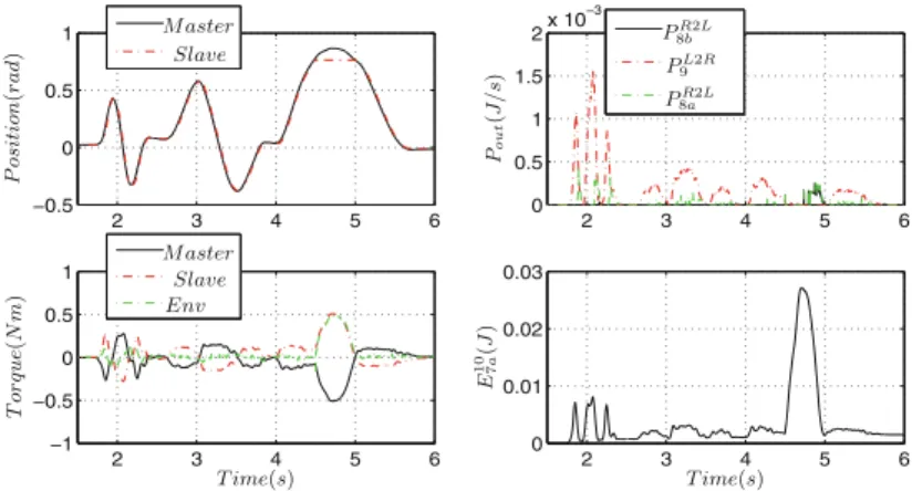
The following experiment considers time delay (compare Fig.6). Figure10
depicts the behavior under symmetric 100 ms roundtrip delay. Comparing Figs.9
4 6 8 10 12 14 16 −0.5
0 0.5 1
4 6 8 10 12 14 16
−0.2 −0.1 0 0.1 0.2
4 6 8 10 12 14 16
0 2 4 6
8x 10
−5
4 6 8 10 12 14 16
0 2 4
6x 10
−3 P o sition ( ra d ) To r q u e ( Nm ) M aster M aster Slave Slave Env Pout ( J/ s ) E
10 7(a
J
)
P8Rb2L
P8Ra2L P9L2R
T ime(s)
T ime(s)
Fig. 10.Wall contact with measured force feedback at 100 ms roundtrip delay
experiment without delay. E10
7a (Fig.10) is always positive, i.e. the subsystem
consisting ofP I,P CL andP CR is still passive.
12 14 16 18 20
−0.5 0 0.5 1
12 14 16 18 20
−0.4 −0.2 0 0.2 0.4
12 14 16 18 20
0 0.5 1
1.5x 10
−4
12 14 16 18 20
0 0.005 0.01 0.015 0.02 P o sition ( ra d ) To r q u e ( Nm ) Pout ( J/ s ) E
10 7(a
J
)
P8Rb2L
P8Ra2L P9L2R
Agent1 Agent1 Agent2 Agent3 Agent3 Env
T ime(s)
T ime(s)
Fig. 11. Position tracking in a multilateral setup (forces and energy behaviour of track2)
A multilateral system as designed in Fig.3can be analyzed in Fig.11. The Agent1
5
Conclusion
A passive module forP Fmeasarchitecture based on the TDPA has been designed
for multilateral architectures in the presented work. It could be shown that the system is not conservative as it is designed in the time domain. As other approaches aiming at absolute stability or passivity of measured force feedback systems consider physical model parameters and therefore limit the force feed-back more gravely and as the PCs dissipate rarely, the proposed approach can be assumed to provide better performance also for general bilateral systems. Furthermore, the module can be used in combination with other passivity based approaches as e.g. the wave variables method. Experiments with time delay proved the system’s adequacy for the classical teleoperation tasks. Subjectively rated, the performance with respect to transparency could be improved
substan-tially in free motion and at fast collisions compared to aP Fcomparchitecture. In
future work the presented approach will be extended to a 4-Channel architecture.
References
1. Anderson, R.J., Spong, M.W.: Asymptotic stability for force reflecting teleopera-tors with time delay. Int. J. Robot. Res.11(2), 135–149 (1992)
2. Artigas, J., Ryu, J.H., Preusche, C., Hirzinger, G.: Network representation and passivity of delayed teleoperation systems. In: IEEE International Conference on Intelligent Robots and Systems (IROS), pp. 177–183 (2011)
3. Daniel, R., McAree, P.: Fundamental limits of performance for force reflecting teleoperation. Int. J. Robot. Res.17(8), 811–830 (1998)
4. Hannaford, B., Anderson, R.: Experimental and simulation studies of hard con-tact in force reflecting teleoperation. In: Proceedings of 1988 IEEE International Conference on Robotics and Automation, pp. 584–589. IEEE (1988)
5. Kanno, T., Yokokohji, Y.: Multilateral teleoperation control over time-delayed com-puter networks using wave variables. In: Haptics Symposium, pp. 125–131 (2012) 6. Khademian, B., Hashtrudi-Zaad, K.: A four-channel multilateral shared control
architecture for dual-user teleoperation systems. In: IEEE International Conference on Intelligent Robots and Systems, pp. 2660–2666 (2007)
7. Lawrence, D.A.: Stability and transparency in bilateral teleoperation. IEEE Trans.
Robot. Autom.9(5), 624–637 (1993)
8. Mendez, V., Tavakoli, M.: A passivity criterion for n-port multilateral haptic sys-tems. In: 2010 49th IEEE Conference on Decision and Control (CDC), pp. 274–279 (2010)
9. Panzirsch, M., Artigas, J., Ryu, J.H., Ferre, M.: Multilateral control for delayed teleoperation. IEEE International Conference on Advanced Robotics, pp. 1–6 (2013)
10. Panzirsch, M., Balachandran, R., Artigas, J.: Cartesian task allocation for coopera-tive, multilateral teleoperation under time delay. In: IEEE International Conference on Robotics and Automation, pp. 312–317 (2015)
12. Tavakoli, M., Aziminejad, A., Patel, R., Moallem, M.: Enhanced transparency in haptics-based master-slave systems. In: IEEE American Control Conference (ACC), pp. 1455–1460 (2007)
13. Tobergte, A., Albu-Schaeffer, A.: Direct force reflecting teleoperation with a flexible joint robot. In: IEEE International Conference on Robotics and Automation, pp. 4280–4287 (2012)

![Fig. 4. Network representation of the 1-port teleoperator proposed in [ 14 ]](https://thumb-us.123doks.com/thumbv2/123dok_es/6844826.837243/4.659.318.591.272.383/fig-network-representation-port-teleoperator-proposed.webp)