Conditions for perfect focusing multiple point sources with the SMS
design method
P. Benítez*
a, Juan C. Miñano
ab, Milena Nikolic
a, Jiayao Liu
a, Jose Infante
a, Fabian Duerr
ca
Universidad Politécnica de Madrid, Cedint, Campus Montegancedo, Pozuelo, 28223 Madrid, Spain;
b
LPI, 2400 Lincoln Avenue, Altadena, CA 91001, USA;
c
Vrije Universiteit Brussel, Pleinlaan 2, 1050 Elsene, Belgium
ABSTRACT
In this work, we demonstrate how it is possible to sharply image multiple object points. The Simultaneous Multiple Surface (SMS) design method has usually been presented as a method to couple N wave-front pairs with N surfaces, but recent findings show that when using N surfaces, we can obtain M image points when N<M under certain conditions.
We present the evolution of SMS method, from its basics, to imaging two object points through one surface, the transition from two to three objet points obtained by increasing the parallelism, and getting to the designs of six surfaces imaging up to eight object points. These designs are limited with the condition that the surfaces cannot be placed at the aperture stop.
In the process of maximizing the object points to sharp image, we try to exhaust the degrees of freedom of aspherics and free-forms. We conjecture that maximal SMS designs are very close to a good solution, hence using them as a starting point for the optimization will lead us faster to a final optical system. We suggest here different optimization strategies which combined with the SMS method are proven to give the best solution. Through the example of imaging with the high aspect ratio, we compare the results obtained optimizing the rotational lens and using a combination of SMS method and optimization, showing that the second approach is giving significantly smaller value of overall RMS spot diameter.
Keywords: lens design, SMS method, image forming, optimization
1.
INTRODUCTION
The problem of perfect focusing, that is, sharp imaging without transverse ray aberrations on the image, is present for a long time. It was solved for a single object point with monochromatic light with a single refractive surface first by René Descartes in the 17th century, using a shape called at present Cartesian oval. Such a shape coincides with a hyperbola, when the object point is located at infinity in the higher refractive index media. This problem of sharp imaging of multiple object points was considered in the early work of Welford and Winston.1,2 Correcting in reference 2 their first conclusion in reference 1, they found that there was no fundamental contradiction that prevents the possibility of sharp imaging of meridian rays from multiple object points using a finite number of rotational symmetric surfaces. The only limitation factor was that this sharp imaging is only possible for meridian rays, not for the full pupil including the skew ones.
Further development of perfect focusing came with the Simultaneous Multiple Surfaces design method (SMS) 3,4, which is a well-known lens design technique initially developed for non-imaging optical designs. Later, the application has been spread to the field of imaging optics4.
2.
SERIES VS PARALLEL DESIGNS
SMS surfaces (in 2D geometry) transform input one-parameter ray sets into output one-parameter ray sets.3 Traditionally, the method involves the simultaneous calculation of a certain number ofoptical surfaces using the same number ofinput ray sets and offers the flexibility to choose the input and output ray sets to satisfy the imaging design condition: the input ray sets are diverging from object points and their associated output ray sets are converging to their associated image points. This type of ray set selection is called object discretization. There is an alternative selection called pupil discretization, when the rays converge to discrete points of the pupil. In this paper we will discuss about designs with object discretization, but the conclusions can be extrapolated to the pupil discretization too.
The calculation of SMS optics is done by applying a constant optical path length condition for each coupled ray set, which is determined by choosing one initial point on each lens profile. For instance, for two object points at infinity, that is, two design angles of opposite sign, the overall symmetry implies an identical optical path length for both ray sets. In the first step the actual result of this design procedure is a set of discrete points and correspondent normal vectors, called SMS chain, which is later converted to complete optical surfaces through the SMS skinning process. It is done by choosing an initial patch which is a segment that interpolates two adjacent points of one of the surfaces of the SMS chain, matching point coordinates and normal vectors at the mentioned selected points. The SMS skinning is done by building SMS chains starting from the interpolated points.
First SMS design was a thin lens, where surfaces shared an edge (Figure 1(a)). This design proved that it is possible to sharply image 2 object points, having two surfaces. The problem was solved both in 2D and in 3D (Figure 1(b)), where the 3D solution was done using free-form surfaces.6,7 This free-form lens solved, by breaking the symmetry, the problem of perfect focusing skew rays that Welford and Winston encountered in their rotational symmetric designs, mentioned in the introduction.
Figure 1. SMS two surfaces designs that sharply image two object points - in 2D (a), and 3D (b)
These thin SMS lenses have a convergence point. Assume that we know one point on one of the surfaces. Applying the SMS algorithm, doing the ray trace and using the constant optical path length condition, we make the SMS chain. Both sequences converge to a single point (point D in Figure 2). As we previously said, after having the SMS chain of points and normal vectors, we use skinning process to form surfaces. We interpolate the initial patch, making sure that it matches initial point coordinates and its normal vectors. Even though, excluding the boundary condition, the initial patch seems to be free, continuing the skinning process and getting close to the convergence point, we can note certain ripple in the optical surfaces. This is a result of calculation no longer being stable, nor optically valid. The fact is that there is a single initial patch that is able to produce a smooth convergence to the point D, which leads to profiles that are analytical (in the sense of expandable in a Taylor series), as was demonstrated on the example of aspheric V-groove reflector design8.
Figure 2. Convergence point of SMS two surface design, showing the error in the calculation if choosing the initial segment badly
Comparing this SMS design that perfectly focuses two object points with the hyperbola mentioned in the introduction (and shown in Figure 3(a)), we get to the following conclusions - both of them have surfaces at the aperture stop, both are unique solutions and the number of object points that we can sharply image equals the number of surfaces.
Now, let us choose two symmetric object points at infinity, and a surface far enough from the aperture stop such that the ray sets do not overlap on the surface (see Figure 3(b)). This means that we can build a Cartesian oval on the upper part of the optical axes that perfectly focuses the off-axis beam v2 into the image point A2.By symmetry, the mirror image of
that hyperbola segment will focus v1 into A1, as shown in the Figure 3(b). This is a trivial solution built using two
Cartesian ovals, and this possibility of sharp imaging of two off-axis object points with a remote aperture stop was already mentioned in the early work of Welford and Winston.1,2 In fact, the design in Figure 3(b), which will be called here “compound Cartesian oval lens”, resembles the best known non-imaging device, the Compound-Parabolic-Concentrator, or CPC, shown in Figure 4.
Figure 3. Transition from one (a) to two (b) perfectly imaged ray bundles in the case of Cartesian oval design
Figure 4. Non-imaging device called Compound Parabolic Concentrator (CPC)
design, where surface size equals the half of beam print (Figure 5(b)). Another difference is that in the first case we have two refractions, and in the second one we have one. Both solutions are unique once the optical path length is fixed. We can visualize the SMS case as two surfaces working in series (since the rays cross them sequentially), while the compound Cartesian oval can be thought of as two surfaces working in parallel. Therefore, we can set the analogy with the series and parallel connected circuits. Additionally, both of designs can be seen as two surfaces sharing an edge, where the only difference is the type of connection between them.
Figure 5. Beam print sizes of two surfaces SMS design (a) and Cartesian oval design (b)
3.
DESIGNING WITH MORE THAN TWO OBJECT POINTS
This section explains the transition from two to three, and more, sharp imaged object points on the already used examples of Cartesian oval design and SMS lens with two surfaces.
3.1 Increasing parallelism in the compound Cartesian oval design
Starting from the trivial case of compound Cartesian oval sharply imaging two object points, we will see next how to introduce a third object point to be sharply imaged by increasing the parallelism. The compound Cartesian oval is moved further away from the aperture stop in order to obtain the degree of freedom to complete the surface at the center with a free patch, as shown in Figure 6(b). Moving it far enough, so that its size is approximately three times the size of the aperture stop, we can choose the free patch to perfectly focus a third on-axis object point (Figure 6(c)). Therefore, using only one surface it is possible to sharply image three object points. Visualizing this as three surfaces in parallel we can see that the parallelism has been increased. In this case, as in the previous one, we have a unique solution.
0 5 10 15 20 25 30
-50 -40 -30 -20 -10 0 10 20 30 40 50
Incidence angle [deg] RMS spot diameter [arc min]
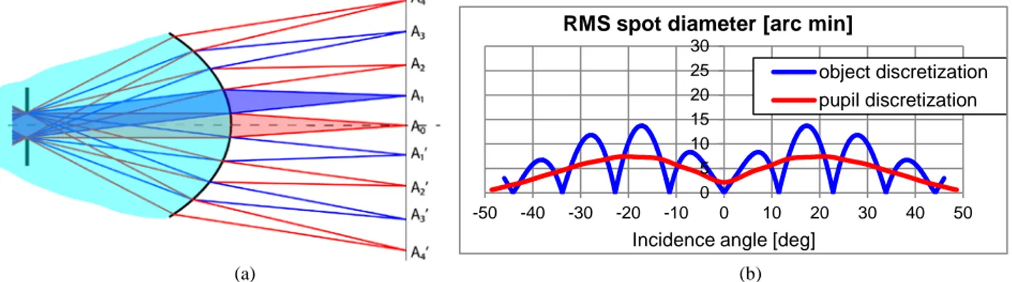
object discretization pupil discretization Repeating this procedure, we can increase the parallelism further. In Figure 7 we can see up to nine perfectly imaged object points through one surface, which was designed in reference 9. In this compound Cartesian oval lens the size of aperture stop is about 1/9 of the size of the lens. Figure 7(b) shows the result of the ray trace on the lens, shown in the blue line that the angular RMS of this design is null for the selected field angles, and shows ripples in between the nulls. As a curiosity, if instead of designing the lens with object discretization, as done so far, the pupil discretization is consider, the angular RMS is averaged (red line in Figure 7(b)), as deeply discussed in reference 9.
Figure 7. Compound Cartesian oval design (a) and calculated RMS for both types of discretization (b)9
3.2 Series-parallel combinations in SMS designs
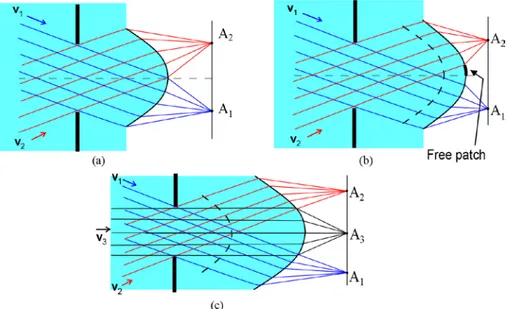
We have just proven that increasing parallelism in the compound Cartesian oval design leads to perfect imaging multiple point sources. It has also been shown that in the case of thin SMS lens we have a fixed initial patch (i.e, with no degrees of freedom to choose it) and a unique convergence point. In that particular design, we sharply image two object points. In order to introduce the third ray bundle to be perfectly focused, we need to get another degree of freedom which would be in moving one surface away from the aperture stop and then choosing the initial patch. This occurs because by increasing the thickness of SMS lens (Figure 8(b)), we no longer have the convergence point, and therefore the seed patch is nearly free10.
Figure 8. SMS two surfaces lens with fixed seed patch (a) and nearly free seed patch (b)
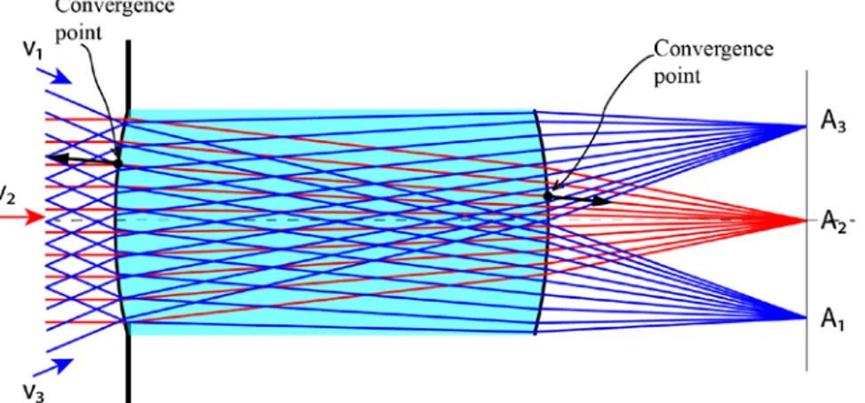
If the second surface is far enough from the aperture stop, this new degree of freedom of the initial segment can be used to couple an additional on-axis ray set11. Starting with determining the convergence points and deriving the full lens profile from them using Fermat’s principle, the unique analytical solution was obtained in the form of Taylor series expansion11 (Figure 9). This type of design is analogue to a combination of series plus parallel connection circuit. The problem was also solved in 3D, simultaneously obtaining two free-form surfaces12.
Figure 9. The convergence points in this design are characterized by the special case that the on- and off-axis rays passing through share identical points and normal vectors.
Two previously described transition processes from two to three object points (shown in Figure 6 and Figures 8-9) have certain similarities. The first one is that in both designs we started from the unique solution. By moving one surface away from the aperture stop, we gained additional degrees of freedom, shown in the form of free patch. This free patch was then chosen to enable introducing the third ray bundle. The results are again two unique solutions, with no free patches, that sharply image three object points.
We can conjecture a general rule of thumb to calculate the number of points we can perfectly image depending on the number of surfaces we have in our system and how far they are from the aperture stop. This can be formulated in the following way: we can measure each surface size in units of the beam print on it, and add the surface sizes in those units, that is, in 2D:
𝑁𝑢𝑚𝑏𝑒𝑟𝑜𝑓𝑜𝑏𝑗𝑒𝑐𝑡𝑝𝑜𝑖𝑛𝑡𝑠 (2𝐷)≤ ∑ 𝐸 �𝐸𝑥𝑡𝑒𝑛𝑠𝑖𝑜𝑛𝐸𝑥𝑡𝑒𝑛𝑠𝑖𝑜𝑛𝑜𝑓𝑜𝑓𝑏𝑒𝑎𝑚𝑠𝑢𝑟𝑓𝑎𝑐𝑒𝑝𝑟𝑖𝑛𝑡�,
and applied to 3D round field:
𝑁𝑢𝑚𝑏𝑒𝑟𝑜𝑓𝑜𝑏𝑗𝑒𝑐𝑡𝑝𝑜𝑖𝑛𝑡𝑠 (3𝐷)≤ ∑ 𝐸 �𝐸𝑥𝑡𝑒𝑛𝑠𝑖𝑜𝑛𝐸𝑥𝑡𝑒𝑛𝑠𝑖𝑜𝑛𝑜𝑓𝑜𝑓𝑏𝑒𝑎𝑚𝑠𝑢𝑟𝑓𝑎𝑐𝑒𝑝𝑟𝑖𝑛𝑡�2.
Let us look at a system of 6 surfaces shown in Figure 10(a). It has a f/3 objective with focal length 30mm and FOV=28 degrees. Applying previously described rule, we should be able to sharply image up to eight object points. Using the SMS design method to design it, we obtained the expected results, as shown in the RMS spot size in Figure 10(b). Therefore, at least in the examples considered the rule of thumb seems valid.
Figure 10. Six surface SMS design perfectly focusing 8 ray bundles (a) and RMS spot diameter (b)
EFL 30mm F/3 Scale: 4.30 MN 08-Jul-14
5.81 MM
(a) (b)
0 0.1 0.2 0.3 0.4 0.5
-16-14-12-10 -8 -6 -4 -2 0 2 4 6 8 10 12 14 16
RMS spot diameter [mm]
4.
APPLICATION TO OPTIMIZATION
Maximizing the number of sharply imaged object points we are trying to exhaust the degrees of freedom of aspheric and free-form lenses. The indication of this exhaustion is the flatness of the RMS curve and its fast divergence outside the field of view shown in Figure 10(b). SMS designs that use all the degrees of freedom are close to a good solution, that is, close to a good local minimum in optimization nomenclature.
On our path to finding a good design we can follow different optimization strategies. One is combining SMS surfaces with standard surfaces and optimizing also free parameters of SMS (for example, the position of vertices, free patches, wave-fronts). An alternative is to use the SMS design as a starting point for a standard optimization. The example of such an optimization was done for the case of imaging with high aspect ratio using free-form lens of two surfaces that perfectly focuses three ray bundles12. The 3D design mentioned in section 3 was used. It was fitted with an x-y polynomial and introduced to Code V software where the default optimization was done (Figure 11). In reference 13 the comparison of this optimized design with an optimized rotational symmetric lens was also shown, demonstrating significantly smaller RMS spot diameter in free-form case (Figure 12).
Figure 11. RMS spot diameter for the contour plots of the SMS free-form lens with high aspect ratio before and after the optimization13
5.
CONCLUSIONS
It has been demonstrated that sharp imaging of multiple object points is possible, both on the example of compound Cartesian oval lens, as well as on standard two surfaces SMS design. The conditions are that the surfaces are not at the aperture stop, making it feasible to perfectly focus additional ray bundles by increasing the parallelism. The general rule of thumb that can help in the initial assessment of the number of point sources that a given system can perfectly image has also been suggested. Furthermore, it has been indicated that the SMS designs of exhausted degrees of freedom can be used as a good starting point for optimization, and that the method itself gives a direct algorithm to the solution. The analysis of more designs to test the accuracy of the rule of thumb will be desirable in the future.
AKNOWLEDGMENTS
Authors thank the European Commission (ADOPSYS: FP7-PEOPLE-2013-ITN Grant Agreement No. 608082;NGCPV: FP7-ENERGY.2011.1.1 Grant Agreement No. 283798), the Spanish Ministries (SUPERRESOLUCION: TEC2011-24019, GUAKS: RTC-2014-2091-7), and UPM (Q090935C59) for the support given to the research activity of the UPM - Advanced Optics Group for making the present work possible.
REFERENCES
[1] W. T. Welford and R. Winston, "On the problem of ideal flux concentrators," J. Opt. Soc. Am 68, 531-534, (1978).
[2] W. T. Welford and R. Winston, "On the problem of ideal flux concentrators: Addendum," J. Opt. Soc. Am 69, 367-367, (1979).
[3] J. Chaves, [Introduction to Nonimaging Optics], CRC Press (2008).
[4] J. C. Miñano and J. C. Gonzalez, "New Method of Design of Nonimaging Concentrators," Appl. Opt. 31, 3051-3060 (1992).
[5] J. C. Miñano, P. Benítez, W. Lin, J. Infante, F. Muñoz and A. Santamaria, "An application of the SMS method for imaging designs," Opt. Express 17, 24036-24044 (2009).
[6] P. Benítez, J. C. Miñano, J. Blen, R. Mohedano, J. Chaves, O. Dross, M. Hernandez and W. Falicoff, "Simultaneous multiple surface optical design method in three dimensions," Opt. Engineering 43, 1489-1502 (2004).
[7] P. Benítez, R. Mohedano and J. C. Miñano, "Design in 3D geometry with the simultaneous multiple surface design method of nonimaging optics," Proc. SPIE 3781, Nonimaging Optics: Maximum Efficiency Light Transfer V, 12 (1999).
[8] D. Grabovickic, P. Benítez and J. C. Miñano, "Aspheric V-groove reflector design with the SMS method in two dimensions," Opt. Express 18, 2515-2521 (2010).
[9] J. Liu, J. C. Miñano, P. Benítez and W. Lin, "Single optical surface imaging designs with unconstrained object to image mapping," Proc. SPIE 8550, Optical System Design, 855011 (2012).
[10] F. Muñoz, P. Benítez and J. C. Miñano, "High-order aspherics: The SMS nonimaging design method applied to imaging optics," Proc. SPIE. 7061, Novel Optical System Design and Optimization XI, 70610G (2008). [11] F. Duerr, P. Benitez, J. C. Miñano, Y. Meuret and H. Thienpont, "Analytic design method for optimal
imaging: coupling three ray sets using two free-form lens profiles," Opt. Express 20, 5576-5585 (2012). [12] F. Duerr, P. Benítez, J. C. Miñano, Y. Meuret and H. Thienpont, "Analytic free-form lens design in 3D:
coupling three ray sets using two lens surfaces," Opt. Express 20, 10839-10846 (2012).