Titulo:
The Strategies Associated with The Migration of Networks to 4G
Autor:
Rubén Fernández
Titulación:
Ingeniería Técnica de Telecomunicaciones esp. En Sistemas de
Telecomunicaciones
Centro de lectura: Politechnika Lodzka
Tutor:
Dr. Malgorzata Langer
Migration of Networks to 4G
UPM RUBEN FERNANDEZ SANTNA
The networks need to provide higher speeds than those offered today. For it, considering that in the spectrum radio technologies is the scarcest resource in the development of these technologies and the new developments is essential to maximize the performance of bits per hertz transmitted. Long Term Evolution optimize spectral efficiency modulations with new air interface, and more advanced algorithms radius. These capabilities is the fact that LTE is an IP-based technology that enables end-to-end offer high transmission rates per user and very low latency, ie delay in the response times of the network around only 10 milliseconds, so you can offer any real-time application.
LTE is the latest standard in mobile network technology and 3GPP ensure competitiveness in the future, may be considered a technology bridge between 3G networks - current 3.5G and future 4G networks, which are expected to reach speeds of up to 1G .
LTE operators provide a simplified architecture but both robust, supporting services on IP technology. The objectives to be achieved through its implementation are ambitious, first users have a wide range of added services like capabilities that currently enjoys with residential broadband access at competitive prices, while the operator will have a network fully IP-based environment, reducing the complexity and cost of the same, which will give operators the opportunity to migrate to LTE directly.
redes 4G
(LTE)
Las redes necesitar proporcionar velocidades mayores a las ofertadas a día de hoy. Para ello, teniendo en cuenta que en tecnologías radio el espectro es el recurso más escaso, en la evolución de estas tecnologías y en los nuevos desarrollos es esencial maximizar el rendimiento de bits por hercio transmitido. Long Term Evolution optimiza la eficiencia espectral con nuevas modulaciones en la interfaz aire, así como los algoritmos radio más avanzado. A estas capacidades se suma el hecho de que LTE es una tecnología basada en IP de extremo a extremo que permite ofrecer altas velocidades de transmisión por usuario y latencias muy bajas, es decir, retardos en los tiempos de respuesta de la red en torno a sólo 10 milisegundos, por lo que permite ofrecer cualquier tipo de aplicación en tiempo real.
LTE es el último estándar en tecnología de redes móviles y asegurará la competitividad de 3GPP en el futuro, pudiendo ser considerada una tecnología puente entre las redes 3G – 3.5G actuales y las futuras redes 4G, de las que se esperan alcanzar velocidades de hasta 1G. LTE proporcionará a las operadoras una arquitectura simplificada pero robusta a la vez, soportando servicios sobre tecnología IP. Los objetivos que se persiguen con su implantación son ambiciosos, por una parte los usuarios dispondrá de una amplia oferta de servicios añadido con capacidades similares a las que disfruta actualmente con accesos a banda ancha residencial y a precios competitivos, mientras que el operador dispondrá de una red basada en entorno totalmente IP, reduciendo la complejidad y el costo de la misma, lo que dará a las operadoras la oportunidad de migrar a LTE directamente.
INDEX
Glossary ...5 Summary ...7 Introduction...8 Objectives...9 Chapter 1...10 3G Evolution...101.1 Background. ...10
1.1.1 Before 3G...10
1.1.2 UMTS ...12
1.1.2.1 Services offered by UMTS...13
1.1.2.2 Modulation Technique (CDMA)...14
1.1.2.3 Problem ...14
1.1.2.4 RF Spectrum...14
1.1.2.5 Radio Interface ...15
1.1.2.6 Basic Parameters...15
1.1.2.7 New Concepts...16
1.1.3 3G Research...16
1.2 Standardization...17
1.2.1 Standardization process...17
1.2.2 3GPP...17
1.2.3 ITU activities with respect to IMT-2000...21
1.3 3G Spectrum...23
1.4 Evolution of the system...25
1.5 Architecture of the system evolved...26
Chapter 2...27
TECHNIQUES FOR ACCESS TO THE MEDIUM...27
2.1 Transmission Systems...27
2.1.1 OFDM...27
2.1.2 SC-FDMA...31
2.2 Channel programming and adaptation of date rate...33
2.2.1 Downlink scheduling...34
2.2.2 Uplink scheduling...35
2.2.3 Inter-Cell interference...36
2.3 Selective retransmission support...36
2.4 Multiple Antennas...37
2.5 Multicast and Broadcast support...38
2.6 Spectrum flexibility...39
2.6.1 Flexibility in the duplex systems...39
2.6.2 Flexibility in frecuency band of operation...40
2.6.3 The bandwidth flexibility...40
2.7 Modulation Schemes...41
MANAGEMENT...42
2.8 THE OPERATIONAL CHALLENGE...44
2.8.1 Service Offer Requirements...45
2.8.2 The Technical Challenge...45
2.8.3 The Technical Tool Box...45
2.8.3.1 Customer Equipment...45
2.8.3.2 Access Line and Aggregation/Backhaul Networks...45
2.8.3.3 Backbone Networks ...46
2.8.3.4 Control Platform ...46
2.8.3.5 Service Platform ...46
2.8.4 The Global Vision...46
2.8.4.1 Vision for an Overall Architecture Supporting Triple and Quadruple Play ...46
2.8.5 Key Issues to Consider When Designing Network and IS Infrastructures for Triple and Quadruple Play ...47
2.8.5.1 Convergence and Mutualization...47
2.8.5.2 Quality of Service ( Q o S )...47
2.8.6 Customer Premises Equipment ( CPE ) and Home Network...48
2.8.6.1 The Home Network Complexity ...48
2.8.6.2 Distribution of Functions between Network and IS Platforms and Residential Gateways...48
2.8.6.3 The Home Network Paradox...48
2.8.6.4 The Home Device and Applications ...49
2.8.7 Access Lines...49
2.8.8 Access Networks, Aggregation, and Backhauling...49
2.8.9 An Illustration of the Fixed Access Network Transformation from Internet Access Support to Triple Play Support...49
2.8.10 Backbone Networks...49
2.8.10.1 Content Delivery...50
2.8.11 Service and Resource Control...50
2.8.11.1 Core Control and Application Servers...50
2.8.11.2 Service Platforms ...50
2.8.11.3 Information System...50
2.8.11.4 The Customer Front - End ...51
2.9 THE OPERATIONAL CHALLENGE...51
2.9.1 Focus on the Service Management Center Function ( SMC )...51
2.10 THE CUSTOMER EXPERIENCE IN BROADBAND TRIPLE ...51
2.10.1 The Customer Journey...52
2.11 NEXT GENERATION NETWORKS (NGNs)...52
2.11.1 Management...52
2.11.1.1 Fault Management ...53
2.11.1.2 Configuration Management ...53
2.11.1.3 Accounting Management ...54
2.11.1.4 Performance Management ...54
2.11.1.5 Security Management ...54
2.12 MANAGEMENT OF NG SERVICES...55
2.12.1 Security Management of NG Services...55
2.12.2 Device Configuration and Management of NG Services...56
2.12.3 Billing, Charging, and Settlement of NG Services...56
2.13 NETWORK AND SERVICEMANAGEMENT FOR NGN...56
2.13.1 Introduction...54
2.13.2 Network Management Operation Requirements...55
2.13.3 Service Management Operation Requirements...56
2.13.4 Service Enhancement Requirements...57
Chapter 3...58
LTE AND WIRELESS...58
3.1 Background...58
3.2 Wireless Technologies...59
3.2.1 3GPP Technologies...61
3.2.2 Competing Technologies...63
3.3 Wireless Technologies Comparasion...65
3.3.1 Latency...66
3.3.2 Spectral Efficiency...67
3.4 Cost and Market Volume...69
Chapter 4...71
4.2 Division of functions between RAN and CN...72
4.3 Architecture RAN...72
4.3.1 Radio Access Network of WCDMA/HSPA...73
4.3.2 Radio Access Network of LTE...73
4.4 CN Architecture...74
4.4.1 Core GSM network used by ECDMA/HSPA...74
4.4.1.1 MBMS, Multicast, Broadcast...75
4.4.1.2 Roaming...75
4.4.1.3 Control Policies and Pricing...78
4.4.2 The core network SAE: Envolved Packet Core...78
4.4.2.1 SAE Gateway...80
4.4.2.2 MME...81
4.4.2.3 S1 Flex...81
4.4.2.4 Roaming...81
4.4.2.5 Control Policies and Pricing...82
4.4.3 WCDMA/HSPA connected to the Envolved Packet Core...82
4.5 Architecture of the Protocols of Interface Radio...82
4.5.1 RLC: Radio Link Control...83
4.5.2 MAC: Medium Access Control...84
4.5.2.1 Logical Channel and Transpot...84
4.5.2.2 Downling and Uplink Programming...85
4.5.2.3 HARQ...86
4.5.3 PHY: Physical Layer...86
4.5.4 LTE State...87
4.5.5 Data Flow...87
4.5.6 Radio Interface...89
4.6 Qos, Quality of Service...90
Chapter 5...91
GLOBAL DEVELOPMENT...91
5.1 Background...91
5.2 Data rate...93
5.2.1 Peak Velocities...93
5.2.2 Impact of RF signal quality and U.E...94
5.2.3 Exchange of throughput of cell among many users...94
5.2.4 Impact of the head of protocol on the application of throughput final...95
5.2.5 Data rate of final user...95
5.3 Latency...96
5.3.1 Latency of the level of control...96
5.3.2 Latency of the level of user...97
5.3.3 Latency of air interface...97
5.3.4 Latency of the user plane end to end...98
5.3.5 Pre-Programming versus programming requiered for the remedy UL...98
5.4 Qos and VoIP support...98
5.5 Handover among many cells...99
5.6 Interoperability test...99
5.6.1 IODT...101
5.6.2 IOT...101
5.7 Customer Test...101
5.8 The 4th generation in the world...102
5.9 Services and applications...102
5.10 Advantages and disadvantages...103
Conclusions...105
ANNEX I...106
ANNEX II...108
Glossary
•
3GPP: 3rd Generation Partnership Project
•
3GPP2: 3rd Generation Partnership Project 2
•
ARIB: Association of Radio Industries and Businesses
•
ATIS: Alliance for Telecommunication Industry Solutions
•
CCSA: China Communications Standards Association
•
CDMA: Code Division Multiple Access
•
CDMA2000: Code Division Multiple Access 2000
•
EDGE: Enhanced Data Rates for GSM Evolution
•
E-UTRAN: evolved Universal Terrestrial Radio Access Network
•
ETSI: European Telecommunications Standards Institute
•
EV-DO: Evolved Data Optimized
•
FDD: Frequency Division Duplex
•
FRAMES: Future Radio Wideband Multiple Access System
•
GPRS: General Packet Radio Services
•
GSM: Global System for Mobile communication
•
HARQ: Hybrid Automatic Repeat-reQuest
•
HSPA: High Speed Packet Access
•
HSDPA: High Speed Downlink Packet Access
•
HSUPA: High Speed Uplink Packet Access
•
HSS: Home Subscriber Server
•
IEEE: Institute of Electrical and Electronics Engineers
•
IPTV: Internet Protocol Television
•
LTE: Long Term Evolution
•
MBMS: Multimedia Broadcast Multicast Service
•
MBSFN: Multicast-Broadcast Single-Frecuency Network
•
MIMO: Multiple Input Multiple Output
•
MME: Mobility Management Entity
•
NGMN: Next Generation Mobile Networks
•
PCI: Peripheral Component Interconnect
•
PCRF: Policing and Charging Rules Function
•
PDSN: Packet Data Serving Node
•
PDC: Personal Digital Cellular
•
PS: Packet Switched
•
QoS: Quality of Service
•
QAM: Quadrature Amplitude Modulation
•
QPSK: Quadrature Phase-Shift Keying
•
RAN: Radio Access Network
•
RTT: RadioTransmission Technology
•
SAE: System Architecture Evolution
•
SC-FDMA: Single Carrier Frequency Division Multiple Access
•
SGSN: Serving GPRS Support Node
•
TDD: Time Division Duplex
•
TDMA: Time Division Multiple Access
•
TIA: Telecommunications Industry Association
•
TTA: Telecommunications Technology Association
•
TTC: Telecommunication Technology Committee
•
TTI: Transmission Time Interval
•
UMB: Ultra Mobile Broadband
•
UMTS: Universal Mobile Telecommunications System
•
UTRA: Universal Terrestrial Radio Access
•
UTRAN: Universal Terrestrial Radio Access Network
•
WCDMA: Wideband Code Division Multiple Access
Summary
This thesis exposes the broad theoretical study of the new wireless technology called LTE. First of all, it should be mentioned that this third generation technology is being implemented gradually in our country, sodevelopment of this work is focused to show the most important featuresof this technology, considering its main advantages and disadvantages.
LTE is the latest standard in wireless networking technology and ensure competitiveness in the future 3GPP and may be considered a technology bridge between the existing 3G/3.5G networks and future 4G networks, which are expected to reach speeds of up to 1 Gbps. Will provide operators with a simplified but robust architecture at a time, supporting IP technology services, as this kind of applications are those that dominate the wireless telecommunications market.
Its main objective is to provide a mobile system able to achieve data transfer rate of 100 Mbps downlink and 50 Mbps uplink. LTE operates in frequencies with variable bandwidths to 20 MHz. Will also provide low latency in order to reduce access times to a service and network response to your request. In addition to these technical improvements, the economic aspect is also important in the development of LTE, including costs of deployment and commissioning as well as migration to LTE UMTS stations.
Introduction
Telecommunication systems of second generation such as the Global System for Mobile Communication (GSM), allowed wireless voice traffic. Currently the number of mobile phones exceeds the number of fixed telephone and mobile phone penetration nears 100% in several markets. This explosive growth in the number of mobile phone users, joined the state of the art suggests a strong demand for mobile broadband applications, such as, the Internet navigation of high speed, sending and receiving e-mail, the mobile TV, fast downloading of multimedia content or interactive games. Satisfy that demand, getting the services attractive to the user while allow operators to reduce the operating expenses primarily requires continue progress in the development of today's mobile networks.
Is how has come to a constant evolution of mobile broadband, and the way it has been deployed technologies like GSM, GPRS, EDGE, WCDMA (UMTS), HSPA and LTE is currently waiting in with regard to 3GPP technologies. The long term evolution of UTRAN (Universal Terrestrial Radio Access Network - Network of Universal Terrestrial Radio Access) is a technology developed for packet radio access optimized high-speed data and low latency for also support voice services.
Objectives
GENERAL OBJECTIVES
• Develop a theoretical investigation of the characteristics of the new wireless technology for wireless
broadband called LTE (Long Term Evolution).
• To study the feasibility of implementing this wireless technology in the field of telecommunications
and wireless service.
SPECIFIC OBJECTIVES
• Analysing the structure necessary for the deployment of LTE wireless networks.
• Investigate modulation techniques present in this technology.
• Assess LTE compared with other similar technologies, analyzing in most technical and general
aspects.
• Analyze the potential technical and economic implications, in conjunction with the development,
which could happen by the implementation of this technology within the domestic market.
Chapter
1
3G Evolution
In this first chapter presents a review of the evolution of cellular networks delving on concepts related to the Third Generation Mobile Telecommunications (3G) and migratory routes towards the same. In order to achieve a prior knowledge to the study being conducted in the following chapters.
1.1 Background.
Since the first experimental activities with the radio communication in 1890, the paththat has advanced mobile radio communication has been quite extensive. To understand the complexities that have the 3G mobile communication systems today, it'simportant to know as they appeared, as well as evaluating the evolution of cellular systems, from an expensive technology to a few individuals, a communication systemphone used by almost half the world's population.
The development of mobile technologies has also changed, from a national or regional interest, to become a global task undertaken by standards developing organizationssuch as the Third Generation Partnership Project (3GPP).
Cellular technologies specified by the 3GPP are more developed in world, with a number of users exceeds 2 billion in 2006. The latest study developed in 3GPP, is an evolution of 3G radio access referred to the long-term evolution (LTE) and the evolution of packet core network access (SAE).
1.1.1 Before 3G.
It all started decades ago with the deployment of analog cellular services. In the U.S. Federal Communications Commission (FCC) approved the first commercial telephone self-service office in 1946, operated by AT & T. In 1947 AT & T also introduced a concept of frequency reuse cellular radio, which became fundamental to all mobile communication systems[22].
The first steps on the way communications were dominated by telephone monopoly, which developed because of the high absorption of subscribers, which resulted in the use of mobile communications to become an international concern, inviting industry to participate in the process.
The first international mobile communication system is the analogue NMT system (Nordic Mobile Telephony) which was introduced in the Nordic countries in 1981 while in North America was introduced analog AMPS (Advanced Mobile PhoneSystem). Other analog cellular technologies were deployed around the world, such as TACS (Total Access Communication System) and J-TACS (Japanese Total Access Communication System).All of them had an equipment of similar characteristics, with a quality of deficient sound, existing the Crosstalk between the users, which was a common problem, including in addition that it was of great size and very little aesthetic. With an international system, as NMT arrived the concept from roaming or itinerancia, also giving services for users who travel outside the local area of their operator. This originated a ampler market for the telephony, thus catching to more companies in the area of the movable communications.
norms of one second generation of movable communications.
In Europe, the administration of telecommunications CEPT1, initiated the GSM (Global System for Mobile communications) and thus to develop a project for all the European continent based on the mobile phone system. GSM continued with their activities in 1989 in just created ETSI (European Telecommunications Standards Institute). After evaluating the proposals given in the middle of the decade of the 80, which were TDMA, CDMA and FDMA, last standard GSM is based on TDMA.
The development of a digital cellular standard was performed simultaneously by TIA (Telecommunications Industry Association) in the U.S., resulting in TDMA based IS-54 standard, which is referred to below as US-TDMA. A little later the development of a standard called CDMA IS-95 was completed by the TIA in 1993. In Japan, the second generation TDMA standard was also developed, which generally refers to PDC.
All these standards were of narrow band, oriented towards a bandwidth reduced for the services of voice. With the second generation the opportunity arrived to offer services on data in movable communications networks. The main services of data introduced in 2G are: the text message (SMS) and the circuit of commutation of packages of data, that allows to the service of the electronic mail and other applications. The speed peak of the data transmission in 2G initially was of 9.6 Kbps. The high speeds of data transmission later introduced in the evolved systems 2G, by means of the allocation of Time manifolds slots to a user and by the modified systems of codification.
Data packets via the cellular systems became a reality during the second half of 1990, with the GPRS (General Packet Radio Services) introduced in the GSM and data packets are also included to other cellular technologies As the Japanese standard PDC (Personal Digital Cellular). These technologies are often called 2.5G. The success of the iMode service in Japan on wireless data gave a clear indication of the potential applications of packet data in mobile systems, despite the slow speed of data transmission supported at this time.
With the advent of 3G and higher bandwidth of the UTRA radio interface was possible a wide range of new services that were mentioned only in 2G and 2.5G. The development of 3G is now handled by the 3GPP, however, initial steps were carried out 3G in early 1990, well before the formation of the 3GPP. The internationalization of the norms and standards was an important factor in determining the basis for 3G. GSM began as a pan-European project, but soon attracted interest from around the world where GSM is deployed in a number of countries outside Europe. GSM is currently deployed in over 160 countries worldwide.
1.1.2 UMTS
UMTS delivery images, graphics, video communication and another type of broadband information, as well as voice and data simultaneously. The main long-term goal of the third generation is to integrate all kinds of services offered by the different technologies and current networks : GSM, EDGE, DECT (Digital Enhanced Cordless Telephone ), ISDN, Internet, etc.
The advantages of UMTS with respect to the existing cellular networks can be summarized as follows: - Increase the capacity and quality of the voice.
- Multimedia applications with higher data rates.
- Highest peaks in the data rates for the transmission of information.
To achieve all this, the new technology will be based on a technique completely different to the well-known in GSM/EDGE, called WCDMA (Wideband Code Division Multiple Access) . Due to the large bandwidth required for the new signs, it has been necessary to allocation of new frequency bands. Part of the spectrum has been allocated for UMTS, also in every European country and some Asians, this spectrum is has split auctioned or led to competition between the operators concerned to a very high cost.
The new system, UMTS, will offer new and better services, such as multimedia services and high-speed services that are easy to use, and that will address all the needs and individual preferences of users.
The market for UMTS comprises a wide range of applications, which can be classified into six main types of services:
1. Voice (S - speech). The voice service is a symmetrical service with the same amount of information in the link of rise (UL) than in the fall (DL). Corresponds with voice services point-to-point and many points (teleconference). It also includes voice mailbox.This is a basic service of voice between 8 and 16 kbitls.
2. Simple Messaging (SM - Simple Messaging). It is a asymmetric service which is considered as the evolution of the SMS service (Short Message Service ) of GSM.This is type services e-mail and messaging between 9.6 and 16 kbitls. It also includes services in e-commerce simple as orders and payments.
3. Circuit-switched data (SD - Switched Data). This symmetrical service provides access to low-speed LAN of marking, access to the Internet and intranet and fax to a data rate of 14 kbith.
4. Multirnedia Average (MMM - Medium Multimedia). This service is assumed as asymmetric and will work in bursts. Includes the services of predominant a single direction: access to LAN networks, intranet and the internet; applications to work in collaboration; interactive games; services of lottery and betting; messaging services and electronic commerce more sophisticated as multipoint and public information.
5. High multimedia (HMM - Alto Multimedia). It is a asymmetric service, such as the previous one, which requires higher bit-rates and sizes of files. Applications include: high-speed LANS, access to the intranet and the Internet; audio and video clips on demand; and purchase online.
6. High interactive multimedia (HMM). Symmetric service that requires a data rate reasonably continuous and high-speed with a minimal delay. It is primarily for services of video telephony, video conferencing , collaborative work and telepresence.
The first three classes of services are seen as logical extensions of the mobile market 2º generation and the last three are entirely to the new market of mobile multimedia. Table 3-1 shows a summary of the main characteristics of the different services.
Service Kind of Service Rate of bits (Kbps) Asymmetric Factor Transmission Mode
HIMM High Interactive Multimedia 128 1 Circuit
HMM High Multimedia 2000 0,005/1 Package
MMM Medium Multimedia 384 0,026/1 Package
SD Switched Data 14 1 Circuit
SM Simple Messaging 14 1 Package
S Speech 12 1 Circuit
1.1.2.2 Modulation Technique (CDMA)
UMTS combines W-CDMA and TD-CDMA (Time Division - Code Division Multiple Access). CDMA is a technique of multiple access spread-spectrum (SSMA - Spread Spectrum Multiple Access Technique). SSMA uses signals with a transmission bandwidth that is several orders of magnitude larger than the RF bandwidth required minimum. SSMA has many properties that make it particularly suitable for use in the environment of mobile communications in radio. This technique converts a signal of narrowband in a signal of broadband by multiplying the original signal by a sequence of pseudo-noise (PN). SSMA is not very efficient in bandwidth when used for only a few users, but if it is in a scenario of a large number of users, since many users can share the same anchojde band widened. Another fundamental reason why we are considered systems SSMA for communications without cable is by resistance to the spread multipath with fade.
In CDMA sequence PN used to multiply the signal of narrow-band called spreading code. All users of a CDMA system use the same carrier frequency and can be transmitted simultaneously without which there is no interference between them, because each user has its own data code word pseudo-random that is approximately orthogonal to any other word of code used by another user. For the detection of the original signal, the receiver needs to know the word of code used for the transmitter. Each mobile station operates independently without any kind of knowledge about the rest of the users.
It is important to indicate that in UMTS used two types of different codes: codes "scrambling" and codes of channel. Both codes have a different nature and also have a different role in the link of rise and linkage of depression:
• The code "scrambling" does not affect the bandwidth of the signal, applies once the signal has been widened. It belongs to the family of codes type Gold and are not in any type of orthogonality between them, if they do not apply the code "scrambling" right to the received signal the result is a signal similar to white noise Gaussian. Its function is to split the signal from different sectors and cells in the link of the descent. While the link of rise, each terminal shall be identified by a code "scrambling".
• The code of channel is responsible for widening the signal from the data rate original until the rate of chip. It belongs to the family of codes type OVSF and are orthogonal to each other, to apply the code correThe function of this code is to separate the connections for each user within the cell in the link of the descent. The function of this code is to separate the connections for each user within the cell in the link of the descent. In regard to the link of rise, the code of channel distinguishes between the data channel and the control channel signalling or transmitted from the same terminal.
1.1.2.3 Problem "near-far"
It is caused by the fact that the sequences of widened from different users are not exactly orthogonal to each other, so after the correlation appear certain contributions other than zero, which added to the original signal, cause noise, this noise level is called ground noise after decorrelation.
The main features of CDMA could be summarized as follows:
• The same frequency spectrum can be shared by many users of a CDMA system. And both TDD and FDD can be used.
• CDMA does not have a limited number of users, since the system gradually degrades overall performance due to an increase of the soil of noise in a linear fashion , according to the number of users is increased. In turn, the performance improves when the number of users is decreasing, because that decreases the ground noise.
• The undesirable effect of spread with multipath fading is substantially reduced. This type of systems are not only resistant to these disturbances of the channel but are also capable of taking advantage of the different echoes from the multipath effect to improve the performance of the system. This process is carried out by a type of receptor called receiver Rake, which combines the information obtained from the reception of various versions delayed the original signal.
Is affected by the problem near-far, which can be resolved by a proper control of power.
1.1.2.4 RF Spectrum
The use of the spectrum is different depending on the specific situation of each region or country. The European organization ERC (Europeo de Radiocomunicaciones Commitee) has awarded 155 MHz of spectrum as a band for the 3º generation terrestrial, figure 3-3. The government approves that every part of the spectrum is offered to 3G operators, except a small amount to private applications of high speed broadband .
The radio interface can operate in two modes: mode Frequency Division Duplex (FDD ) or the mode Time Division Duplex (TDD). The possibility of operating in both FDD and TDD allows effective use of available spectrum in accordance with the frequency given in the different regions. In FDD transmissions of links of rising and falling used two different frequencies , therefore are allocated to the system a couple of frequency bands with a determined separation. On the other hand, TDD is another duplex method based on the transmission of the link of rising and falling at the same frequency by means of the synchronization of time intervals.
1.1.2.5 Radio Interface
Unlike GSM, where the coverage and capacity of the cells are concepts that can be studied separately, in UMTS, on the other hand, both are correlated and should be considered simultaneously in the study of dimensioning.
1.1.2.6 Basic Parameters
The basic parameters in UMTS for the radio interface on WCDMA are proposed by ETSI. Due to the current process of standardization, some of these parameters can be modified. The main parameters are summarized in table-2.
Multiple Access Technique DS- WCDMA
Duplex Scheme FDD
Chip Rate 3.84 Mcps
Carrier 5 Mhz spacing between operators
Technical or multiple variable rate Variable spreading factor & multicode
Usar date rate 8kbps; 12.2kbps; 32kbps; 64kbps; 128kbps; 256kbps; 384
kbps; 2Mbps
Transmitted peak power in the mobile terminal 2ldBm terminals with voice service only or 24dBm for data terminals
Peak power transmitted to the base station 43dBm or 46dBm depending on traffic conditions in the area.
Table-2 Basic parameters of the WCDMA radio interface
The technique used is based on the multiple-access techniques by spread spectrum . UMTS uses a particular type called multiple access broadband by direct sequence, DS-CDMA, which converts a signal of narrowband in a signal of broadband with aspect of noise before transmission.
1.1.2.7 New Concepts
UMTS, is based on a technology totally different to TDMA in GSM, therefore appear new concepts with which it is necessary to become familiar in order to study and understand the behavior of these new cells. Among them, the Node B indicated the base station in UMTS. These new concepts are:
1 . Load in the cell or increase of the noise. 2. Soft Handoff or change in gradual cell.
1.1.3 3G Research.
In parallel with the large deployment and evolution of 2G mobile communication systems in 1990 were put great efforts in research activities on the 3G.
In Europe, the Commission of the European Union (the EU) finances the program mainly call Investigation and Development in Technologies outposts of the Communications in Europe (RACE), carrying the first stage of the initial investigation where 3G was named like Universal System of Comunicaciones Móviles (UMTS).
In the second phase of RACE, project CODIT (Code Division Testbed) and project ATDMA (Advanced TDMA Mobile Access) were developed like concepts based on technologies Wideband CDMA (WCDMA) and Wideband TDMA.
The following phase in relation to the European investigation was the ACTS (Technology and Advanced services of Communication), that carried the project Future Radio Wideband Multiple Access System (FRAMES), that was the one in working with the terrestrial component of the interface UMTS radio .The definition of the scheme of original multipie access of FRAMES (FMA), satisfied the requirements that had to realise for the systems of terrestrial mobile radio of 3G. The FRAMES was completed in 1996, on the basis of decisions in different parts from the world, and in addition it combined broadband technology WCDMA and TDMA, with or without relaxation.
At the same time in Japan, the Association of Radio Industries and Businesses (ARIB) was in the process of defining a 3G wireless communication technology based on WCDMA. Korea also began work on WCDMA at the time, and the U.S. developed like a concept called WIMS (WWW Interactive Multipurpose Server). The FRAMES project was presented to the 3G standardization activities in ETSI, when other multiple access proposals were also introduced by the industry. ETSI proposals joined in five groups, meaning also that the WCDMA proposals from both countries, U.S. and Japan did the same between them.
1.2 Standardization
1.2.1 Standardization process.
To establish a standard for mobile communications is not a simple task, it must follow a continuous process.Standardization forums are constantly changing their standards, to try to meet new demands for services and functions. This process is different in different forums, but includes four phases which are illustrated in Figure 1.1:
1.Specification: where you decide what to get with the standard.
2.Architecture: which are determined the main building blocks and interfaces. 3.Detailed specifications: where each interface is specifically detailed.
4.Testing and Verification: where the interface specifications have shown the result of work in real life.
Figure 1.1 Stages of standardization and the iterative process
These phases can be iterar and in addition superpose themselves. For example, they can be incorporated, be modified or handicappeds during the last phases, if the technical solutions require it. In the same way, the technical solutions in the detailed specifications can change due to the problems found in the phase of test and verification.
Standardization begins with the requirements phase, where the standards body decides what should be done with the standard.This phase is usually relatively short. In the architecture phase, the standards are decided on the architecture initially must meet with the requirements, also include decisions on benchmarks and standardization of the interface to use. This phase is usually quite long and can change the requirements. This phase is usually quite long and can change the requirements. Then we have the detailed specification phase where interfaces are identified. During this process, the standards body may find that you must change the aspects that were taken by the decisions in the architecture, or even in the requirements phase.
Finally, we continue with the testing and verification phase that is generally not a real part of the standardization, but is carried in parallel through testing by suppliers and interoperability testing between suppliers.This phase is the ultimate test of the standard. During this stage can be found in the standard errors and can also change the decisions of the other phases.To verify the quality of standard are needed the products therefore the application of these starts after or during the detailed specification.
The test and verification phase ends when the tests are stable can be used to verify that the equipment is meeting with the rule or standard. Usually, the period is one to two years from the time the standard is completed in its entirety until commercial products are on the market. However, if the standard starting from zero, it may take more time because there is not set of components where to begin.
1.2.2 3GPP
ETSI: European Institute of Standards and Telecommunications Europe
ARIB: Association of Radio Industries and Businesses Japon
TTA: Telecommunications and Technology Association Korea
CCSA: Standards Association and Communications of China China
ATIS: Alliance for Telecommunications Industry Solutions North-America
TTC: Committee on Technology and Telecommunications North-America
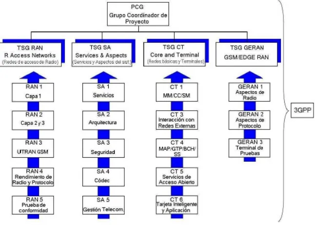
The technical part of 3GPP is composed of four groups of technical specification or TSG (Technical Specification Groups), see Figure 1.2, each is composed of different working groups, these are:
The TSG RAN (Radio Access Network), this group works on the specification of HSPA / LTE, is responsible for the functions, interfaces, and protocol of the access network. It consists of the following groups:
- RAN 1, is responsible for the physical definition (Layer 1) of the Access Network UTRAN. This includes specification of modulation, channel coding, physical layer measurements, etc.
- RAN 2, Works with the interface protocols radio used in the top of the physical layer. This includes layer protocols 2 for the transmission of data.
- RAN 3, is responsible for the overall architecture of UTRAN. This includes the definition of the interface between access network entities and the specification of the transport network.
- RAN 4, it is responsible for the radio frequency (RF) and the management of the radio resource requirements of the operation.
- RAN 5, produces evidence of specification based on the documents of the RAN 4.
The TSG SA (Services and System Aspects), is responsible for the architecture and service definition and consists of the following groups:
- SA 1, is responsible for the high level of service characteristics and requirements. It also produces documents in the system and service capabilities, used like a reference for other groups.
- SA 2, defines the network architecture and its features to be supported by network entities based on the documents of the SA 1. It also produces specifications that are used as reference by the group in charge of detailed interface specifications.
- SA 3, establishes safety requirements for the system and produce security specifications for the algorithms to be applied in the network.
- SA 4, works in the specification language, audio, video and multimedia codecs applied to circuits and packages.
- SA 5, specifies the architecture, the procedures for the related with the management of the network interface, including the configuration and performance management.
para establecer sesiones de comunicación de circuitos.
- CT 3, is responsible for the interconnection of networks, networks between 3GPP and networks of circuits or external packages. This includes signalling or protocol of interconnection.
- CT 4, is responsible for the definitions of complementary services such as call transfer or SMS.
- CT 5, works with UMTS OSA (Open Service Access or Service of Open Access) and produces Applications Programming Interfaces to facilitate UMTS services.
- CT 6, is responsible for the format of the Subscriber Identity Module (SIM), specifying the data of the content of the SIM card and your organization.
Radio Access Network), is responsible for the evolution of GSM/EDGE based on Radio Access Network. As UMTS comes from the GSM technology, it is very significant for a network core and for services of great expectation.This is the reason why this technical group begins initially of the ETSI, and finally moved to the organization 3GPP at the end of 2000. It consists of the following groups:
- GERAN 1, is the equivalent of RAN 1 and defines the physical interface of network access GSM/EDGE.
- GERAN 2, is the equivalent of RAN 2 and works in the definition of radio protocols.
- GERAN 3 is the responsibility of the adoption of specification testing of network access.
In the field of application of UMTS evolved, the structure of the 3GPP will not change. All of the TSG and most of its working groups will be expanded its scope in order to cover all the requirements and specifications of the evolution of UMTS.
There is also a parallel project called 3GPP2 which was formed in the year 1999 and the responsibility to develop the specifications for 3G, but for CDMA2000, which is the 3G technology of the CDMA 2G, based on the standard ES-95. This global project also has the organization's participation of partners such as ARIB, CCSA, TIA, TTA and TTC.
The scope of 3GPP in the beginning was the world's production of specifications for a mobile system 3G based on the network core of GSM evolved,including WCDMA and TD-CDMA. The task of maintaining and developing GSM/EDGE has been added at a later stage in the 3GPP.
The work in the 3GPP is carried in ITU into account of the recommendations and the results obtained, in addition, the partners are obliged to identify regional needs that may give rise to different alternatives of the standard. Examples of this are the frequency bands regional and special requirements of local protection of a region.
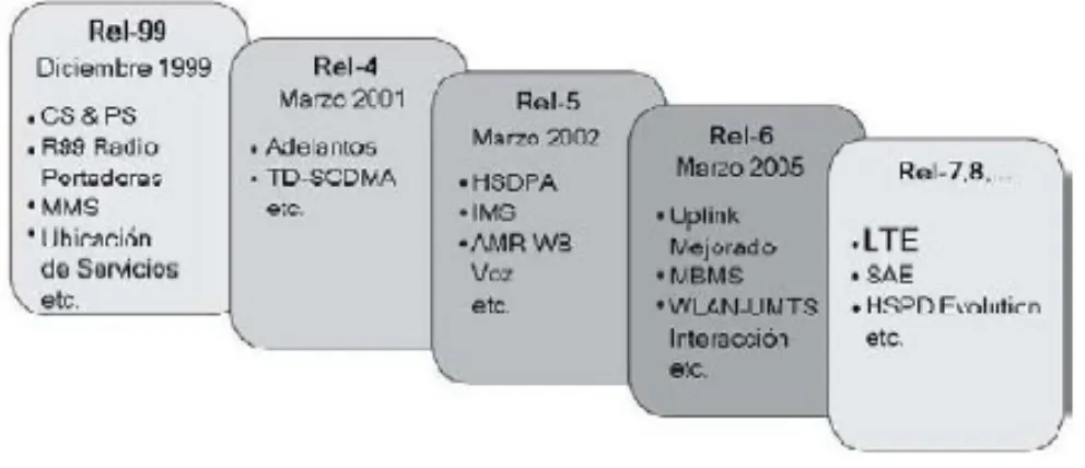
The specifications are updated after each series of meetings of the TSG, which are made 4 times a year. These specifications are called emissions or versions that are more known by its English name of Releases.The documents of the 3GPP is divided within the Releases (see Figure 1.3 ), when each of these has a set of added features in comparison with the previous version. These characteristics are defined and agreed upon by the Elements of work and carried by the TSG. The following is a brief description of the versions of the 3GPP.
Release 99 (Rel-99): this is the first version of specifications 3G, which contains all the features necessary to comply with the requirements of IMT-2000 for access radio of WCDMA. It is also established the basis for the future traffic of high-speed transfer , as well as the circuit-switched in packet switching.
Release 4 (Rel-4): contains the changes in the domain of the network core and create new communications interfaces. For the transport you can use ATM or IP in the domain of voice. They are also introduced other features, such as:
· Multimedia in domain circuit-switched (CS-Circuit Switched).
· Handover in real time in the domain of packet switching (PS-Packet Switched).
· Support IPv6 as optional and MMS.
Release 5 (Rel-5): describes the best speed of the data channel for the downlink (HSDPA-High-speed downlink Packet Access), which allows speeds of up to 14.4 Mbps and presents the structure of the network to be fully IP instead of ATM. It also introduces:
· a Quality of Service (QoS) in the domain name PS for the whole journey (fin a final).
· IMS (IP Multimedia Subsystem): IPv6 support and use of SIP to establish session.
Release 6 (Rel-6): improves the speed of the uplink (using HSUPA) of up to 5.76 Mbps, introduces MBMS, and interoperability between UMTS and WLAN. The main improvements are:
· Handover between 3G and WLAN.
Release 7 (Rel-7): published in March of the year 2007, improves the speeds of the uplink and downlink (HSPA+ ). It uses MIMO which is the use of multiple antennas in the receptors, it is defined LTE. Among the major improvements is:
· The use of 64QAM modulation for modulation.
· CPC: The connection of packages continues to data users.
· Introduction of LTE/E-UTRAN.
· Melting NodoB and RNC (Radio Network Controller) in the access network radio.
· VoIP for mobile phones.
Release 8 (Rel-8): used like a technique of access, and a variable bandwidth from 1.25 MHz to 20 MHz. Among the improvements are:
· Introduction of SAE/EPS in the network architecture.
. Support for access not WCDMA.
· BY as air interface.
· MIMO: settings of 4x4.
· Beamforming or configuration of the beam: smart antennas.
· IMS common to FMC.
· Priority of multimedia service.
Figure 1.3 Releases del 3GPP
1.2.3 ITU activities with respect to IMT-2000
ITU is the United Nations agency which is responsible for regulating telecommunications in the world, between the different operators and managers.
The areas of activity of the ITU IMT-2000 are:
· ITU Radiocommunication Sector (ITU-R), which is responsible for studies and drawing of recommendations on aspects of radio of IMT-2000 and systems of the future.
· Standardization Sector (ITU-N), which deals of studies relating with the network aspects and applications of IMT-2000 are; convergence of services fixed-mobile, mobility management, multimedia functions mobile, interworking of service, interoperability of equipment and mobile Internet.
For the rules of the Radio Regulations, the works has developed by the Commission Study Group 8 of Mobile Services of the ITU-R, within it establishes the special Task Group 8 (Task Group) dedicated to IMT-2000, which works supported both of the ITU-R and standardization sector ITU-T.
IMT-2000 can be specified with a set of interdependent recommendations of the ITU, providing the framework for a wireless access global linking various networking systems terrestrial and satellite.The number of the Recommendations of IMT-2000 defines a frame of reference for the development of 3G systems, it also sets a series of objectives, description of services, general characteristics of the radio interfaces, spectrum requirements, movement of terminals, and electromagnetic compatibility requirements .
The specifications of the radio interfaces have been developed in various recommendations of the ITU-R. The recommendation ITU-R M-1455 defines the fundamental characteristics of the radio interfaces of IMT-2000. The M-1455 contains basic features proposals, it gives a list of the recommended values in different magnitudes.This recommendation expresses that the radio interface of IMT-2000 would be a single standard, with various modes of operation, which could be classified in CDMA, TDMA or a combination of both. The group includes CDMA systems inexpensive DS-CDMA with FDD, TDD and FDD systems multi-carrier.
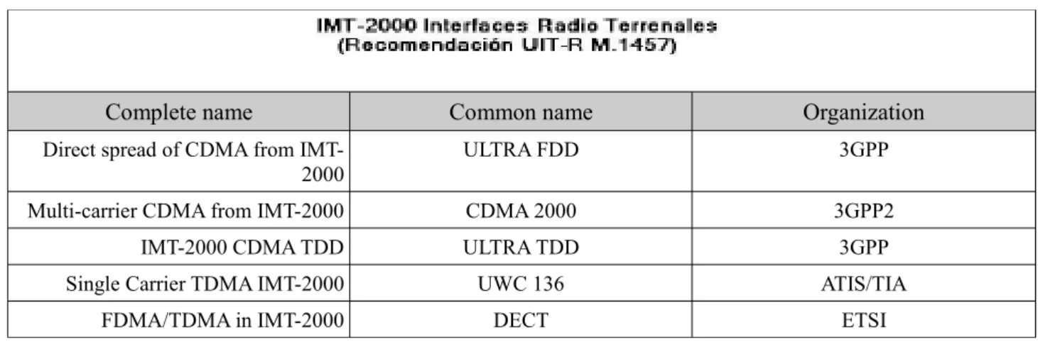
The main recommendation is the Recommendation ITU-R M. 1457, which identifies the detailed specifications of the radio interface of IMT-2000. The recommendation includes a family or set of five interfaces terrestrial radio which are shown in Figure 1.4 , as well as the organizations that develop the specifications.
Complete name Common name Organization
Direct spread of CDMA from
IMT-2000 ULTRA FDD 3GPP
Multi-carrier CDMA from IMT-2000 CDMA 2000 3GPP2
IMT-2000 CDMA TDD ULTRA TDD 3GPP
Single Carrier TDMA IMT-2000 UWC 136 ATIS/TIA
FDMA/TDMA in IMT-2000 DECT ETSI
Figure 1.4 Interfaces Radio Terrestrial IMT-2000
In each radio interface has been developed the assessment process, convergence and the achievement of quality objectives for different environments radio operational, while ensuring global compatibility and international roaming.
the ITU-R Working Party 8F, is the development on the subsequent systems to IMT- 2000, appointed currently as IMT-advanced.In this development include studies of services and technologies, market forecasts, principles of standardization, the estimation of the needs of the spectrum and the identification of frequency bands candidates for IMT-advanced. The spectral work also involves exchange of studies between IMT- advanced and other wireless technologies.
1.3 3G Spectrum
The work in the development of the spectrum of 3G mobile systems, began when the World Radio Conference (WRC) of ITU in the year 1992, identified the frequencies that were available for use in future IMT-2000, around 2 GHz. Goal 3 G original is a unique and comprehensive air interface of IMT-2000. In practice, the 3G systems are closer to this goal than when they were 2G, since WCDMA has proved to be the more dominant of the standard IMT-2000 within the commercial deployment.
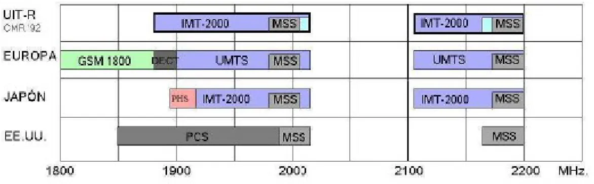
Most of the developments in WCDMA have been specified in the spectrum for 3G, which identifies the frequency bands 1885-2025 MHz and 2110-2200 MHz (see Figure 1.5 ), as intended to be used by national administrations that wish to implement IMT-2000.
Figure 1.5 Spectrum of frequencies
The resolution, something dissenting between the regions of the frequency bands allocated for 3G, it means that there is no single band that can be used for 3G roaming throughout the world. Great efforts, however, have been in the definition of a small set of bands, which can be used to facilitate roaming and as well the devices multi-band can provide greater efficiency in this type of world service.
An additional spectrum for IMT-2000 was identified at the World Radio Conference 2000 (WRC-2000), where it was considered the need to add 160 MHz of spectrum, this was foreseen by the ITU-R. Furthermore, it was established that WCDMA would be deployed in 17 existing bands of frequency 2G identified by IMT-2000 and that are currently used by GSM. This approach is known as reorganization, which helped in part by the deployment of WCDMA in the U.S. , in the cellular bands in 850 MHz and the PCS band in the 1900 MHz, since there were no new frequencies available for this deployment. Also this reorganization WCDMA in GSM bands has begun in Europe and in Asia.
The agreements of frequency in all world described in recommendation ITU-R M. 1036, it can identify which parts of the frequency spectrum bands are paired (paired bands) and which are unpaired (unpaired bands). For the spectrum of bands paired, the frequency bands of uplink and downlink, are identified by the management of Frequency Division Duplex (FDD). The unpaired, for example, can use Time Division Duplex (TDD). There is to know that the band with greater global deployment 3G continues to be the 2 GHz.
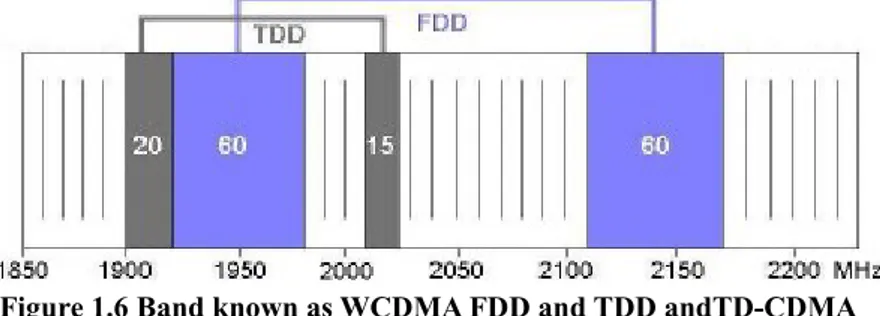
Figure 1.6 Band known as WCDMA FDD and TDD andTD-CDMA
FDD is used in the paired components of the band IMT-2000, of which, the bands 1920-1980 MHz represent the uplink and 2110-2170 MHz the descendant. TDD is used in the components not paired occupying the frequencies of 2010 MHz to 2025 MHz and 1900 MHz to 1920 MHz. This gives an availability of 60+60 MHz for FDD with 12 carriers and 15+20 MHz for TDD with 7 carriers.
The new band IMT-2000 (see Figure 1.7 ) is approximately 2.6 GHz with a total of 190 MHz of spectrum, which are available for the deployment of IMT-2000 and other mobile systems. In Europe, the spectrum includes 2+70 MHz for the FDD systems and 50 MHz of empty space in the middle that can be used, for example, to TDD The same range of 2.6 GHz is also available for the use of mobile phones, including IMT-2000 in the USA.
Figure 1.7 Frequencies about 2.6 Ghz
1.4 Evolution of the system
GSM and WCDMA together represent 85% of subscriptions global mobile, and their participation continues to grow. WCDMA is designed to coexist with GSM, including an uninterrupted handover and terminals of dual mode. Most of the WCDMA networks are deployed in the current GSM network EDGE and EDGE Evolution can be developed in an efficient manner along with WCDMA and its evolution. In the same way, LTE is designed to coexist with GSM and WCDMA.
Figure 1.8 Evolution system
Looking back at history GSM, several countries have reached more than 80% of cellular penetration, and the global account of GSM subscribers exceeded 2 billion in 2006, fifteen years after the opening of the first network. The early experiences of GSM, showed that the growth rates are very high when it has terminals attractive, small size and in addition to possessing a low energy consumption. It took about seven years for GSM reached 100 million subscribers and WCDMA only six years. Currently, there are more than 150 commercial networks WCDMA with more than 130 million subscribers.
1.5 Architecture of the system evolved
Approximately at the same time of the evolution of HSPA and the start of LTE, the 3GPP decided to make sure that an operator can coexist easily between HSPA and LTE through a network core. This work was done by the Working Group SA carrying out the study of the System Architecture Evolution (SAE).
The study of the architecture of the system evolved, it focused on how the network core 3GPP will evolve in the next network core of the coming decades. The current network core was designed in the 1980s for GSM, expanded during the 1990s, for GPRS and WCDMA.
The operation of a network at a general level is quite simple. Base stations are equipped with creating a large mesh in the shape of cell or cell, connecting using radio waves two terminals with the drivers of these base stations (see Figure 1.9 ).This form of diaper is not accidental but that responds to a scheme which allows the reuse of a certain set of frequencies allocated in different cells, provided that these are not adjacent, increasing network performance on the one hand (the number of frequencies available is limited) and saved on the other.
A network is basically around two types of elements and a proper combination of these, enabling communication both between mobile phones, such as between a mobile phone and a telephone. These elements are:
· base station: what they are responsible for transmitting and receiving the signal.
· Pbxs: allow the connection between two specific terminals.
Figure 1.10 Arquitecture 3G
In Figure 1.10 shows the architecture 3G, where the data arrives at the node B ( base station) which is responsible for collecting the signals sent by the terminals, passing these to the RNC or driver of the Radio Network to be processed. The set of nodes and the RNC constitute a structure called Radio Access Network (RAN), which connects the terminals with the network core or Core Network, from which is distributed by the various systems through a series of commutations. According to their destination, shall pass through the MSC (Mobile Services Switching Center) or by the SGSN (Serving GPRS Support node) and GGSN (Gateway GPRS Support Node).
The philosophy SAE is focused on the domain of packet switching and migrate outside of the domain of circuit switching. This is done through the next "Release 3GPP", so as to reach the evolution of the network core packages, Evolved Packet Core which will support both HSPA Evolution and LTE, ensuring that LTE may be deployed in smaller islands, only where necessary. A deployment with a gradual approach can be seen in Figure 1.11.
Figure 1.11 Deployment strategy HSPA and LTE
Chapter
2
TECHNIQUES FOR ACCESS
TO THE MEDIUM
This chapter describes the techniques that you use LTE for the medium access control , explaining primarily as works the uplink and downlink according to the types of air interface that occupies LTE. In addition, it continues with a technical insight of the various systems with which obtains better yields in the transmission of data.
2.1 Transmission Systems
2.1.1 OFDM
OFDM (orthogonal frequency division multiplexing) has been adopted as the system of downlink transmission of 3GPP LTE and is also used for other technologies such as WiMAX and DVB broadcast. The transmission by means of OFDM can be appreciated as a kind of transmission multi-carrier. The basic characteristics of the transmission of OFDM are:
· The use of a relatively large number of subcarriers narrow-band, a simple multi-carrier will consist of few subcarriers, each with a relative bandwidth. For example, a multi-carrier WCDMA with 20 MHz of bandwidth , could consist in four subcarriers, each with a bandwidth on the order of 5 Mhz. In comparison with the other systems, the OFDM transmission may involve several hundreds of subcarriers is transmitted on the same radio link to the same receiver.
. It has a simple rectangular pulse in the time domain configured as shown in Figure 2.1a. This corresponds to a form of sync function frequency-domain , as illustrated in Figure 2.1b.
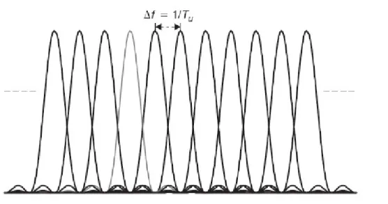
. The compact frequency domain subcarriers with a deviation n f = 1/Tu, where Tu is the time of the modulation of the symbol by subcarrier frequencies (see Figure 2.2 ).
Figure 2.2 Carrier deviation of OFDM
The number of OFDM subcarriers can vary from less than one hundred to several thousand, with a deviation from subcarriers ranging from hundreds of KHz a few KHz. The deviation of subcarrier frequencies to use depends on the types of environments in which it is to operate the system, including such aspects as the maximum expected selectivity of frequency of the radio channel (maximum expected time of dispersion) and the maximum transmission speed of variation channel (maximum expected Doppler spread).
As an example, for LTE basic deviation is equal to 15 KHz. On the other hand, the number of subcarriers depends on the transmission bandwidth, in the order of 600 subcarriers in case of operation on a spectrum allocated 10 MHz, and less or more subcarrier in the case of small or large bandwidths of transmission respectively.
An illustrative description of an OFDM modulator core is presented in Figure 2.3 . This consists of a bank of modulators Nc complex, where each modulator corresponds to a subcarrier OFDM. Transmission is based on blocks, implying that during each interval of OFDM symbol, the modulation of the symbols Cn is transmitted in parallel. The modulation of symbols can be QPSK, 16QAM or 64QAM.
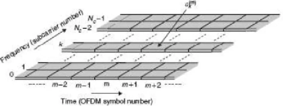
The "physical resource" in the case of the OFDM transmission, it is often illustrated as a grid of time-frequency according to Figure 2.4 , where each column corresponds to a symbol OFDM and each row corresponds to a subcarrier OFDM. Figure 2.4.
Figure 2.4 Grid OFDM time-frequency
The basic principles for the demodulation OFDM are shown in Figure 2.5 , consist of a bank of optical correlators, one for each subcarrier. Taking into account the orthogonality between subcarriers, in the ideal case, two subcarriers OFDM not cause interference between if after the demodulation, taking into account that in the spectrum the neighboring subcarriers clearly overlap, as can be seen in Figure 2.2.
Figure 2.5 Basic Demodulation OFDM
Figure 2.6 Cyclic prefix insertion
Then, this transmission system in the downlink, is attractive for several reasons. Due to the corresponding long-time symbol of the OFDM in combination with a prefix cyclical, OFDM provides a high degree of robustness in front of the selective channel frequency. Although there is corruption of the signal, this can be handled in a principle by medium of the equalization on the receiver side, the complexity of this becomes something unpleasant for deployment on a mobile terminal a bandwidth above 5MHz. In addition OFDM is optimal for downlink, especially when combined with spatial multiplexing.
The additional benefits of OFDM are:
. OFDM provides access frequency domain, thus allowing an additional degree of freedom to the channel dependent compared with HSPA.
· Flexible allocations of bandwidth are easily supported by OFDM, at least from the perspective of base band by the variation in numbers of subcarriers that OFDM uses for its transmission.
· Transmission broadcast/multicast, where the same information is transmitted by multiple base stations, which is simple with OFDM.
2.1.2 SC-FDMA
For the uplink of LTE, has selected a type of transmission with single carrier based on DFT-spread OFDM (DFTS-OFDM), due to the combination of the properties such as:
· Small variations in the instantaneous power of a transmitted signal.
· Possibility of low complexity for a high quality of equalization frequency-domain.
· Possibility of FDMA with flexible allocation of bandwidth.
Figure 2.7 Signal generation DFTS – OFDM
Also, like in OFDM, it is preferable to insert a cyclical prefix for each block in the transmission. The presence of a cyclic prefix allows a minor complexity of equality of the frequency domain in the receiver side. The main benefit of DFT-OFDM, compared with a transmission multi-carrier OFDM, is that it reduces variations in the power of instant transmission, which leads to the possibility of increasing the efficiency of the power amplifier.
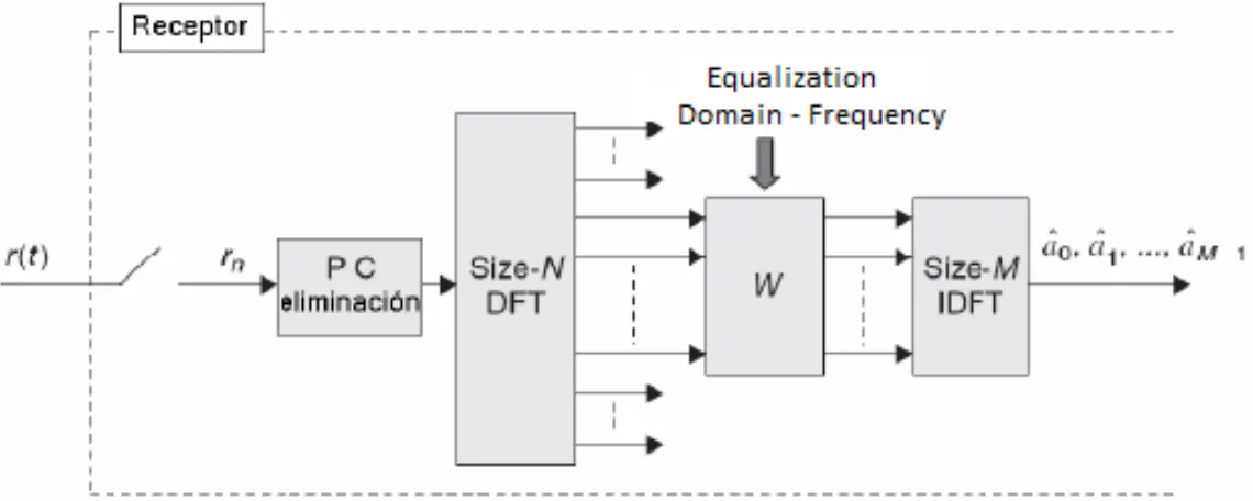
The basic principle of the demodulation DFTS-OFDM is illustrated in Figure 2.8, and the operations are basically reverse the generation of the signal shown above in Figure 2.7.
Figure 2.8 Signal demodulation DFTS – OFDM
The use of a modulation with a single carrier in the uplink, is caused by a lower value in the relationship peak average of a transmitted signal in comparison with the transmission multi-carrier. The relationship peak average of a transmitted signal and the average of the transmitted power, it may be for a given power amplifier. The transmission of single carrier, therefore allows the more efficient use of the power of the amplifier, which translates an increase in coverage that is very important for the limited power of the terminal. On the other hand, the equalisation to handle the corruption of the signal single carrier , because of the withering away of frequency selective, that is a minor issue in the uplink by the few restrictions on the processing resources of signal in the base station in comparison with the mobile terminal.
resource instantaneous bandwidth to a single user, it is not a sufficient strategy in situations in which the speed of data transmission is limited, Mainly by the transmission of power more than bandwidth. In such situations, a terminal is designated to transmit only in a part of the total of the bandwidth, and other terminals can be transmitted in parallel with the rest of the spectrum. Therefore, as the uplink of LTE contains a component of frequency domain multi-access, the transmission system of this link is also called as a Single Carrier - Frequency Division Multiple Access (SC-FDMA).
The key to these transmissions is normally the speed and the significant variations in conditions snapshots of the channel. These variations are due to; fainting by shadow, loss of path dependent in the distance that significantly affect the average received signal and finally, interference in the receiver due to the transmission of other cells and other terminals that also impact the level of interference. All of these variations must be taken into account for a better quality of the link.
2.2 Channel programming and adaptation of date rate.
The heart of the transmission system of LTE, is the use of transmission channels shared, it is well adapted to the different resource requirements posed by data packages and it also makes several other key technologies used by LTE.
The controls programming, in each moment of time, should be allocated for those users that share resources. This also determines the speed of transmission of data to be used for each link, transmission speed adapted that can be viewed as a part of the programming. Programming is a key element and to a large extent determines the overall performance of the downlink, especially in a network very charged. Both transmissions of uplink and downlink are subject to a tight schedule. In relation to HSPA, programming downlink transmits a user when the conditions of the channel have the advantage of using the maximum speed of data transmission, and the Enhanced Uplink (uplink improved), however, as LTE has time domain and also access to the frequency domain, due to the use of OFDM and SC-FDMA on their respective links.
The scheduler to each regional frequencies can select the channel of user with the best conditions. In other words, the configuration of the channel of user in LTE may take into account changes not only in the time domain, such as HSPA, but also in the frequency domain, this is illustrated in Figure 2.9 .
Figure 2.9 Downlink channel scheduling dependent on time and frequency domain
2.2.1 Downlink scheduling.
Initially assumes a downlink based on TDM with a single user programmed in a moment. In this case, the use of radio resources is maximized if in each moment of time, all resources are allocated to the user with the best condition snapshot of the canal:
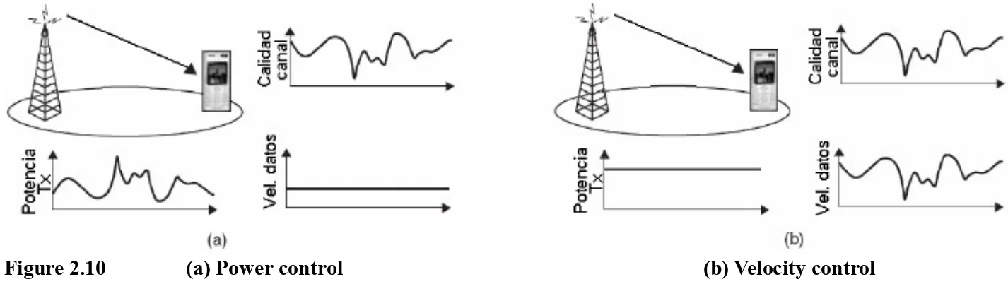
. In the case of the adaptation of the link based on the power control, implies that the lower power possible transmitted may be used for a particular data rate and it also minimizes the jamming of the broadcasts in other cells in a specific link (see Figure 2.10 (a).
. In the case of the adaptation of the link based on the speed control, it implies that the highest values of data transmission speed are achieved for a particular transmitted power or for a particular interference in other cells (see Figure 2.10 (b).
Figure 2.10 (a) Power control (b) Velocity control
However, if it is applied to the downlink, the control of the transmitted power in combination with the programming TDM, implies that the total available from the cells that transmit power, was not used in its entirety. Thus, the speed control of data is generally preferred[1].
The above is an example of channel programming dependent, where the programmer takes into account the conditions snapshots of the link radio. The programming of the user with the best conditions of the link radio, it is often referred to as programming max-C/I (or maximum percentage). Given the conditions for the different links radio, almost at any time there is a channel of user whose quality is close to its maximum point (see Figure 2.11 ). As well, finally the channel used for the transmission tends to have a high quality, and a high transmission speed to be used, by generating a high-capacity system. The gain obtained by the transmission to the users in favorable conditions is commonly known as diversity multi-user, appearing greater profits , large variations of the canal and a large number of users in a cell.