TítuloDesign, Implementation and Practical Evaluation of an IoT Home Automation System for Fog Computing Applications Based on MQTT and ZigBee WiFi Sensor Nodes
42
0
0
Texto completo
(2) Sensors 2018, 18, 2660. 2 of 42. sources of information that interact with the environment and anticipate and predict the actions of the home residents. One of the technologies that has contributed most to the progress of home automation is cloud computing, which offloads home devices from computational-intensive tasks. Nonetheless, in certain home automation scenarios where a fast response and low communications overhead are required, other paradigms have been successful by moving the computing capabilities from the cloud towards the edge of the network [3]. One such paradigm is fog computing, which moves the cloud computational and communication capabilities close to the sensor nodes in order to minimize latency, to distribute computational and storing resources, to enhance mobility and location awareness, and to ease network scalability while providing connectivity among devices in different physical environments [4,5]. To provide such benefits for home automation, four elements have to interact: IoT nodes that collect data (sensor nodes), IoT nodes that embed actuators (actuator nodes), the cloud, and interconnected IoT gateways that exchange messages with the IoT nodes and with the cloud. Communications can be performed through different technologies that, in the case of home automation, are aimed at improving energy efficiency, safety, comfort, and providing audio/video/control systems. These technologies have been proposed for communicating the sensors and actuators installed in a home, either by using independent wired infrastructure (e.g., KNX [6] or LonWorks [7]) or the already existent infrastructure (e.g., X10 [8]). Among these technologies, some of the latest make use of Wireless Sensor Networks (WSNs), which have been applied successfully to fields like train monitoring [9], telemetry [10,11], Industry 4.0 [12–15] or public safety [16,17]. As of writing, ZigBee is arguably the most popular technology for creating WSNs and it has been included in some of the latest commercial [18] and academic home automation developments [19–25]. In addition, WiFi networks (i.e., networks based on the IEEE 802.11 family of standards) have become widespread throughout the world and are one of the most popular ways for accessing the Internet due to their flexibility and low deployment cost. However, although the use of commercial WiFi home automation devices is not as popular as the use of ZigBee-based systems, the growing popularity of the IoT paradigm has led to new applications that base their data communications on WiFi networks [26–28]. This article presents ZiWi, a fog computing Home Automation System (HAS) that bridges the gap between ZigBee and WiFi devices by connecting sensors and actuators seamlessly to make use of such technologies in a home. ZiWi uses WiFi for actuator nodes since, in general, they have to be continuously awake, listening for asynchronous commands, while ZigBee is implemented by the sensor nodes because it is ideal for sending data at periodic intervals in order to save power (since many nodes rely on batteries). Moreover, the system focuses on the growing IoT market and on easing the connection of emerging sensor technologies. Furthermore, ZiWi makes use of the fog computing paradigm to provide connectivity between the user and the different home appliances, not only allowing the user to control them, but also offering automatisms to simplify tasks. This is achieved thanks to ZiWi’s distributed nature: the home controller hardware is kept at the bare minimum for executing real-time tasks, delegating the processing of the data and the decisions on non real-time automated tasks to remote cloud servers. It is important to note that ZiWi proposes a distributed approach instead of a decentralized solution [29]. Both terms have been used as synonyms in some scenarios, so they can be confusing. In the case of decentralized systems, they consist of a network of stars where every central element of each star processes the collected information locally. In contrast, in a distributed system, the different components are located on networked computers that communicate and coordinate to achieve a common goal. This is what is proposed in fog computing: local gateways can communicate with each other and with the cloud to achieve a common goal [4,30]. What can be confusing is that many decentralized systems are also distributed, since they process some information locally but also cooperate with other systems to perform certain actions (e.g., this is the case of some peer-to-peer or blockchain-based systems [31]), so a distributed system can also be decentralized in some applications..
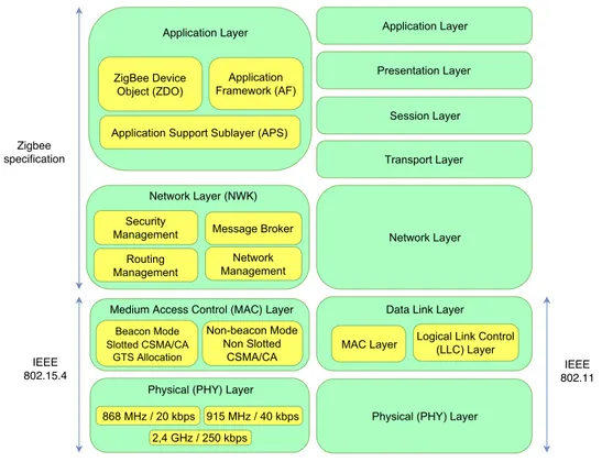
(3) Sensors 2018, 18, 2660. 3 of 42. In the case of ZiWi’s architecture, the term distributed implies that the computational and storage resources are distributed throughout the network in strategic locations to allow the system to respond faster and also to decrease the computational load of the cloud. This is performed by moving part of the computational power towards the edge by means of fog gateways, which perform certain simple tasks that require a fast response. This architecture also allows ZiWi to remain inexpensive in comparison to many commercial systems, which usually make use of complex and pricey home controllers. The designed architecture, together with the use of an open messaging protocol like Message Queuing Telemetry Transport (MQTT) to communicate nodes, make ZiWi more flexible than traditional home automation solutions, whose manufacturers are often reluctant to offer connectivity with third-party systems. Thus, such an openness and the use of widely known technologies provide robustness and ease of construction and deployment, being straightforward for integrating new elements on the ZiWi IoT ecosystem and allowing the user to make use of a wide range of resources to act on devices to obtain information on them or to automate certain events. This article includes three main contributions aimed at creating a cost-effective and duplicable fog computing-based HAS. First, in order to establish the basics, it presents a detailed review of the state-of-the-art of the main and the latest technologies and services for home automation systems. Second, it thoroughly explains the design, implementation and practical evaluation of a fog computing-based HAS that is accessible, easy to configure, low cost and scalable in terms of protocols and technologies. Third, the article describes in detail an HAS that, thanks to the use of open-source software and Commercial Off-The-Shelf (COTS) parts, is easy to build, so it is straightforward for other researchers to replicate the system and the performance tests presented in Section 5. The rest of this paper is structured as follows. Section 2 describes and analyzes the state-of-the-art of home automation technologies and the latest commercial and academic HAS. Section 3 includes an overview of ZiWi’s architecture and its main components. Section 4 details the hardware and software used to implement the different system devices. Section 5 presents the results of different tests that evaluate the performance of ZiWi in real scenarios. Finally, Section 6 is devoted to the conclusions. 2. Related Work 2.1. Home Automation Protocols and Technologies There is a rich variety of protocols and technologies in the field of home automation. Some of them are standard and have been designed by international institutions, while others are proprietary and have been developed by companies. In certain cases, such protocols and technologies have been designed for wired communications, while others are aimed at creating wireless systems. Each of them presents different advantages and disadvantages depending on the deployed scenario. Some of the most popular home automation technologies are KNX-EIB, LonWorks, X10, Insteon, ModBus, BACnet, Z-Wave and EnOcean. In addition, other generic wireless technologies like Bluetooth (IEEE 802.15.1) and WiFi (IEEE 802.11) have been used for controlling devices in home automation installations, since they provide an easy way to communicate with smartphones, tablets and PCs. Regarding WiFi, it is worth mentioning that the WiFi Alliance has recently approved a new standard for wireless connections called IEEE 802.11ah or WiFi HaLow that extends WiFi into the 900-MHz band, allowing for the connection of low-power sensor networks like the ones usually embedded into battery-powered home automation devices. As it was mentioned earlier, ZigBee has to be included in the comparison, since many manufacturers have developed home automation platforms and devices that rely on it. As it can be observed in Figure 1, ZigBee’s protocol stack differs from the one used by WiFi. Actually, ZigBee nodes use Physical (PHY) and Medium Access Control (MAC) layers defined by the IEEE 802.15.4 standard, while the network and application layers are covered by the specifications given by the ZigBee.
(4) Sensors 2018, 18, 2660. 4 of 42. Alliance [32]. In contrast, the term WiFi usually refers to LAN (Local Area Network) technologies, thus including all the layers of the stack.. Figure 1. Zigbee versus WiFi protocol stack.. IPv6 over Low-Power Wireless Personal Area Networks (6LoWPAN) is another emerging technology and, like ZigBee, it provides general purpose, easy-to-use and self-organizing wireless communications for low-cost and low-power embedded devices. Both ZigBee and 6LoWPAN implement IEEE 802.15.4 MAC and PHY layers, but 6LoWPAN has been explicitly designed for an easy interaction with IPv6-based networks, which are still far from being widely used (for instance, as of writing, less than 18% of the users access Google over IPv6 [33]). In the same way, Bluetooth Low Energy (BLE) also supports IPv6 through Internet Protocol Support Profile (IPSP), but it suffers from the same use limitations as 6LoWPAN. The latest version of Bluetooth (Bluetooth 5.0) seems to be a really good fit for low-power home automation devices [34]: with respect to the previous version (4.2), it can reach four times its range, it can transmit twice as fast, it multiplies by eight the previous broadcasting message capacity and it improves the coexistence with other cellular and wireless technologies. However, currently, there are not as many commercial home automation systems and home devices that support Bluetooth 5.0 in comparison to ZigBee and WiFi. In addition, there is a lack of commercial BLE 5.0 SDKs (e.g., Nordic nRF52840 PDK), which is a limitation when developing new hardware. Similarly, there are other good alternatives for providing low-power communications to home devices that require mesh communications (e.g., nRF [35]), but its use, even in home automation research platforms, it actually reduced [36]. Cellular communications technologies like the ones defined by 3GPP (3rd Generation Partnership Project) [37], 4G machine-to-machine communications [38] or Machine-Type Communications (MTC) [39] should also be mentioned. These technologies are still emerging and its use for home automation is actually marginal, although they have been tested in some IoT scenarios [40]..
(5) Sensors 2018, 18, 2660. 5 of 42. Table 1 summarizes the main features of the most relevant home automation technologies previously mentioned. For every technology, the transmission medium, the data transfer rate and whether its specification is open or proprietary are indicated. This latter parameter is essential, since a proprietary protocol, like Z-Wave until 2016, usually suffers from fewer interoperability problems than an open alternative like ZigBee, but developers are attached to the technology. Table 1. Characteristics of the most common home automation technologies. RF: Radio Frequency, EG: Electric Grid, OF: Optical Fiber, TP: Twisted Pair. Technology. Medium. Openness. Data Rate. KNX. EG, RF, TP. Open. 9.6 Kbps. LonWorks. EG, RF, OF, Coaxial, TP. Open. 1.25 Mbps. X10. EG. Open. 60 bps. Insteon. EG, RF. Proprietary. 38.4 Kbps. ModBus. TP. Open. RTU: 19.2 Kbps-TCP: 10/100/1000 Mbps. BacNet. TP. Open. 10/100/1000 Mbps. Z-Wave. RF. Partially open (open-source layer for integration). 9.6 Kbps. EnOcean. RF. Partially open (open OSI layers 1–3). 25 Kbps. ZigBee. RF. Open. 256 Kbps. WiFi. RF. Open. 600/54 Mbps. Bluetooth. RF. Open. 1 Mbps. 2.2. Academic Solutions 2.2.1. Home Automation Systems for Heterogeneous Networks In the last few years, several academic researchers have presented a number of relevant home automation systems based on the use of multi-technology devices. For example, some authors [19] studied the problem of integrating varied wireless technologies (ZigBee, Wi-Fi, GSM/GPRS) in home automation environments. Specifically, the researchers used a LabVIEW-based PC that acted as a ZigBee coordinator for collecting data from different ambient sensors (temperature, humidity, light) and that is able to control certain actuators (e.g., lighting or irrigation). Similarly, other authors made use of a PC as ZigBee coordinator in order to create an HAS based on intelligent power outlets [41]. An example of a multi-transceiver (X10, Serial, EIB, ZigBee, Bluetooth, DTMF, CAN and GSM/GPRS/UMTS) HAS is presented in [20]. In such a paper, the authors detail an indoor ambient intelligence platform and an IP-based messaging protocol to communicate the home automation controller with the rest of the equipment. Baraka et al. [21] presented a low-cost HAS based on the use of a gateway consisting of an Arduino MEGA with Ethernet and ZigBee shields, and an Android tablet that acted as home controller. The system uses ZigBee for connecting wireless sensor nodes and X10 for wired communications. An Arduino MEGA, an Ethernet shield and an Android phone are also used in [42], but, in this case, the sensors and actuators were connected directly to pins of the Arduino. CONDE [43] is another HAS whose objective is to improve energy efficiency in smart buildings. CONDE is decentralized and thus allows for reducing response time and power consumption with respect to traditional centralized systems. CONDE was tested by using MICAz motes, which were able to lower decision delay times and increase energy savings when evaluating lighting and Heating, Ventilation and Air-Conditioning (HVAC) systems. Other researchers have also proposed home controllers and gateways for HAS that support only WiFi [44–46], only ZigBee [22] or both technologies [23–25]. Most of them [22–25] do not use open messaging systems but proprietary ad hoc protocols, while some of the latest use MQTT [45,46] or Extensible Messaging and Presence Protocol (XMPP) [44]. For instance, in [45], it is proposed the use of low-cost WiFi modules to transform a traditional house into a smart home. For such a purpose, the authors make use of ESP8266 WiFi modules for the nodes, a Raspberry Pi 2 for the gateway, MQTT.
(6) Sensors 2018, 18, 2660. 6 of 42. for data exchanges and OpenHAB as home automation server. Similarly, in [46], a simple HAS based on MQTT is presented, but the home controller is implemented on a PC. Regarding ZigBee-based home automation systems, they are not very popular when having to interact directly with mobile devices, but some researchers have demonstrated that it is possible to connect Android phones/tablets to a ZigBee dongle [47]. With respect to hybrid systems, it is worth mentioning the work of Vivek et al. [25], who presented a WiFi-ZigBee gateway aimed at enabling IoT services in an HAS. The home system controller is developed on a Cubietrack board connected to ZigBee and WiFi wireless interfaces that communicate with sensor nodes that collect data on ambient parameters and that are able to actuate on relays that control lights and fans. Another example of heterogeneous HAS is MPIGate [23], which is based on a multi-protocol gateway that integrates sensors and actuators with different network protocols (e.g., EIB/KNX, WiFi, Bluetooth, ZigBee). For the sake of clarity, Tables 2 and 3 show a comparison of the most relevant characteristics of the previously cited academic systems together with the ones of the system proposed in this article. As it can be observed in Table 2, ZiWi is the only academic solution that, at the same time, makes use of MQTT and supports both WiFi and ZigBee nodes. In addition, in contrast to ZiWi, most systems are not open source. Moreover, ZiWi is the only HAS conceived from scratch to harness the benefits of fog computing. Regarding the cost, most academic papers do not indicate the real cost of the presented solutions, although in some cases it is specified that it is low cost (without further details). Just a couple of systems calculate explicitly the cost of the system, but it is difficult to make a fair comparison, since not all the solutions provide the same amount of hardware (i.e., nodes) and features. In the case of ZiWi, the cost was calculated for the hardware used to build the demonstrator evaluated in Section 5, so it includes all the nodes and sensors described later, as well as the cost of the selected WiFi router. It is important to note that, although there are systems where ZigBee and WiFi coexist, they suffer from cross-interference, since their radio channels overlap and, even in non-overlapping channels, out-of-band emissions can cause interference. This issue has been studied in the past [48–50]. For instance, in [50], it is concluded that, in order to avoid cross-interference in the 2.4 GHz band, a 20 MHz bandwidth should be left unoccupied between the operating channels. It is also worth mentioning that there exist commercial solutions to connect WiFi and Ethernet home automation devices with the ones that use ZigBee. For instance, Digi [51] provides Zigbee to IP gateways, but they are relatively expensive (as of writing, a ZigBee-to-Ethernet gateway costs around $100)..
(7) Sensors 2018, 18, 2660. 7 of 42. Table 2. Comparison of the main features of the most relevant academic HAS and the proposed system (part 1). System. Main Objective. Messaging Protocol. Actuation Capabilities. Open-Source Code. Conceived for Fog Computing. Cost. Relevant Features/Challenges. ZiWi. MQTT-based HAS. MQTT. Yes. OpenHAB (Node source code available on GitHub). Yes. e 180 (whole demonstrator). High flexibility, interoperability and scalability. [19]. Intelligent building monitoring. Ad hoc. Yes. No. No. Low cost. Delays due to SMS-based commands. [20]. Indoor ambient intelligence monitoring. Ad hoc. Yes. No. No. Cost-effective. Alarm control center, several scenarios. [21]. Energy efficiency. Ad hoc. Yes. No. No. Low-cost. Heuristic scheduling algorithm. [22]. ZigBee-based HAS. Ad hoc. No. No. No. Not specified. Software designed of the coordinator and terminal node. [23]. Gateway for assisted living applications. Ad hoc, dependent on the assisted living device. Yes. No. No. Not specified. Biometrics and actimetry for assisted living. [24]. HAS for heterogeneous networking. Ad hoc. Open API. No. Cloud capabilities. Not specified. Integrated home appliances with prediction algorithms. [25]. Enabling IoT services in HAS. Ad hoc. Yes. No. No. Not specified. Basic GUI with sensor readings. [41]. Power outlet control and monitoring. Ad hoc. Yes. No. No. e 45 (one smart socket). Experimental analysis with theoretical and empirical measurements. [43]. Smart building energy efficiency monitoring. Ad hoc messages routed with CTP (Collection Tree Protocol). Yes. No. Decentralized architecture. Not specified. Decision-making manager and integration of different applications. [44]. HAS. XMPP. Yes. Openfire. No. Low-cost. Android app for control units Overall delay from UI to Node is less than 600 ms It makes use of ESP8266 WiFi modules. [45]. HAS. MQTT. Yes. OpenHAB. No. Cost-effective (less than $60 for a Raspberry Pi 2, an SD card and four ESP8266 modules). [46]. MQTT-based HAS. MQTT. Yes. No. No. Not specified.
(8) Sensors 2018, 18, 2660. 8 of 42. Table 3. Comparison of the main features of the most relevant academic HAS and the proposed system (part 2). Reference. Home Controller Hardware. Communication Transceivers. Communication Topology. Sensors and Actuators. Node Hardware. ZiWi. Raspberry Pi Model B. WiFi, ZigBee. Mesh. Temperature (LM35, TMP36, DHT11), humidity (HIH-5030, DHT11), luminosity (LDR), motion (Parallax PIR rev. A) and current sensors (ACS712). NodeMCU (ESP8266), Xbee Series 2. [19]. PC. ZigBee, WiFi and GSM/GPR. Star. Temperature (LM-35DZ) and relays. WN-USB ZigBee module. [20]. 32-bit ARM microcontroller. X10, Serial, EIB, ZigBee, Bluetooth, DTMF, CAN and GSM/GPRS/UMTS. Star. Multiple I/O pins for attaching sensors and actuators. Proprietary board based on a 32-bit ARM microcontroller. [21]. Android tablet and Arduino MEGA with an Ethernet shield. X10, ZigBee. Tree. Light and switch modules. Arduino. [22]. 32-bit ARM-Cortex M3 microcontroller. ZigBee. Tree. The paper only suggests different sensors and actuators for the HAS, but it is actually not implemented. CC2530. [23]. -. EIB/KNX, WiFi, Bluetooth and ZigBee. Star. Environmental (door/window opening, light, temperature), biometric (wrist pulse oximeter, body scale, wrist blood pressure, ear thermometer) and actimetry (movement detection, bed/chairs presence, lighting control, water and electricity meter) sensors and actuators. WaspMote platform. [24]. Raspberry Pi 2. WiFi, ZigBee, IrDA, Ethernet. Star. Smart plugs, IP cameras. Raspberry Pi 2 (the controller also acts as sensor node). [25]. Cubietrack board (ARM-Cortex A7). WiFi, ZigBee. Star. Temperature, light and current sensors (ACS712). Relays and dimmers. ESP8266, Xbee ATmega328P microcontroller. [41]. PC. ZigBee. Star. Smart plugs. [43]. -. IEEE 802.15.4. Tree. -. MICAz motes. [44]. -. WiFi, IR. Star. Dust sensor. Commercial UART-WiFi module. [45]. Raspberry Pi 2 model B. WiFi. Star. -. ESP8266. [46]. PC. WiFi. Star. Luminosity sensor (LDR), LED and buzzer. ESP8266.
(9) Sensors 2018, 18, 2660. 9 of 42. 2.2.2. Fog Computing Architectures and Applications Many recent user-centric IoT applications are latency sensitive or require real-time data analysis and decision making. Cloud computing solutions usually cannot fulfill such requirements in many context-aware applications, so, in the last few years, different researchers proposed alternative approaches and optimizations in terms of scalability, economic and environmental effects [52,53]. One such approach is fog computing, originally coined by Cisco in 2012 [4], which was introduced to alleviate some of the above-mentioned problems and to provide a solution to support geographically distributed, end-device mobile, heterogeneous, latency sensitive, and Quality of Service (QoS) aware IoT applications. A comparison between cloud and fog computing together with a performance evaluation is presented in [54]. This article also identifies some key research directions for fog computing such as fog federation, mobile fog computing or semantic-aware fog computing. Regarding fog computing based architectures, Mukherjee et al. [55] provide a comprehensive survey of recent implementations. In the paper, it is distinguished among the following architectures: • • •. • • •. Generic three-tier architecture [56]: it is one of the most widely used in fog computing. It consists of an IoT node layer, a fog layer and a cloud server. Layered approach [57]: it consists of six layers (physical/virtualization, monitoring, pre-processing, temporary storage, security and transport layers). Combined fog-cloud architecture [58]: it is used when there is a different storage and computing capacity in the fog nodes. It is detailed later, since it was the fog architecture selected for implementing ZiWi. Virtualized fog data centers [59]: this architecture enables adding multiple virtualized edge data centers to offload services from traditionally massive data centers. Fog Radio Access Networks (F-RANs) [60,61]: they use remote radio units with caching and signal processing capabilities. Software-Defined Networking (SDN) fog architecture [62,63]: the main difference between the traditional fog architecture and an SDN-based fog is the fog-SDN controller used to support dynamic QoS.. A detailed description on the inner workings of the different fog computing architectures is out of the scope of this paper, but the interested readers can find interesting overviews in [54,64]. Nonetheless, it is worth mentioning that such architectures have been used in multiple fields like smart grids [65,66], smart cities [67,68] or smart health [69]. However, with respect to the application of fog computing to home automation, just a few very recent papers describe practical implementations explicitly conceived for fog computing [70,71]. Such developments make use of an architecture similar to the generic fog computing architecture illustrated in Figure 2. In such a figure, three different IoT networks (A, B and C) exchange data with a fog layer that allows for communicating them with the services provided by the cloud. In the fog layer, there are two sub-layers. The bottom sub-layer is made of gateways that respond quickly because of their proximity to the IoT nodes. However, the gateways of the bottom sub-layer usually embed less powerful hardware than the gateways of the fog upper sub-layer. In addition, in such an upper sub-layer, the gateway at the top is the point of entry to the fog, while the other gateways provide different services or share among them certain data in order to reduce the latency response from the cloud..
(10) Sensors 2018, 18, 2660. 10 of 42. Remote Users. Other IoT Networks. Third-Party Services Cloud. Fog Layer Upper Sub-Layer Gateway. Gateway. Gateway. Bottom Sub-Layer. Gateway. IoT Node. Gateway. IoT Node. IoT Network A. IoT Node. Gateway. IoT Node. IoT Network B. IoT Node. IoT Network C. IoT Node Layer Figure 2. Generic fog computing architecture.. 2.2.3. Protocol Compatibility Approaches In order to create uniform, scalable and easily configurable systems, different researchers have addressed the compatibility issues associated with the diversity of protocols, technologies and standards that exist in the field of home automation. The solutions presented usually propose universal and open standards. Some of them use a configuration system based on the eXtensible Markup Language (XML) format that can be easily exchanged among standards [72]. Other researchers [73] suggest the use of the Universal Plug and Play (UPnP) open standard as a communications protocol for devices on a local network, since it offers technology independence and increases scalability. The most relevant initiative for adding plug-and-play capabilities to intelligent devices based on transducers (i.e., on sensors and actuators) is the ISO/IEC/IEEE 21451 standard (previously known as IEEE 1451). The standard is highly-flexible and generic, which implies a certain degree of complexity that makes it difficult to implement in the resource-constrained devices usually found in home automation installations. For such a reason, some authors proposed modified and simpler versions aimed explicitly at home automation applications [74]. Besides standards, messaging protocols have arisen as a way for connecting heterogeneous IoT nodes. Such protocols are really useful in applications where different components are designed and implemented independently using diverse programming languages or hardware platforms, but they.
(11) Sensors 2018, 18, 2660. 11 of 42. have to be able to communicate, collaborate in tasks, and share data among them. Traditionally, this kind of communication was performed by exchanging files, sharing a common database or by using calls to remote procedures (i.e., creating Remote Procedure Call (RPC) based systems), but, in the last few years, it finally was derived in what is called a messaging system or Message-Oriented Middleware (MOM). A messaging system centralizes communications in order to minimize the coupling between the components of a distributed system. This decoupling and the use of asynchronous communications allow for carrying out more robust communications: the components to be communicated do not have to be working at the same time, so they delegate the delivery of the data to a messaging system, what enables them to stay focused on the information to be sent instead of on how to send it. A messaging system is also in charge of establishing and managing the connection points and channels created among the different clients. It is usually implemented as a software process called a “messaging server” or “messaging broker”. Most messaging brokers can cooperate to provide advanced features like load balancing, fault tolerance, or sophisticated routing systems, which are really useful in IoT applications. Messaging systems transmit data over channels that connect a transmitter and a receiver virtually. There are basically two channel models: the peer-to-peer queue model and the publish/subscribe model. The peer-to-peer queue model is currently the most used. It allows a transmitter to send a message to a queue where it will be read by a particular receiver. Note that, although the transmitter sends the message to a queue, it does not indicate who the receiver is: it only specifies the name of the queue where the data are shared. Any receiver that knows the name of the queue can connect to it and collect the message, which will be removed from the queue. Thus, the model does not guarantee that a specific receiver will always collect the data, but it does guarantee that, if someone connects to the queue and collects the message, it will only be collected once and by a single receiver. In the publish/subscribe model, messages are transmitted to one or more recipients who have previously expressed interest in them. When the transmitter publishes a message on the channel, it sends a copy to each of the output channels. Each of these output channels has a single subscriber, which is the only one that can consume the published message once. Therefore, each subscriber receives the message only once and the various consumed copies disappear from their respective channels. There are other variants of the peer-to-peer queue and publish/subscribe models, but the ones previously described remain as the most commonly implemented in popular messaging systems (which are briefly described in the following paragraphs). One of the most widespread messaging systems is Java Messaging Service (JMS), which is actually an Application Programming Interface (API) that is part of the Java Enterprise Edition (JEE) and it is aimed at exchanging asynchronous messages among two or more components developed with JEE. In practice, to make use of JMS, it is necessary to have a JMS provider that manages sessions and message queues. Since JEE version 1.4, the JMS provider is included in all the implementations of JEE servers, but there are other alternatives like Apache ActiveMQ, HornetQ, OpenJMS or IBM’s WebSphereMQ. Another messaging system is Advanced Message Queuing Protocol (AMQP), which is an open standard for the development of MOMs. It is oriented towards scenarios where high performance, flexibility, security and reliable routing/delivery of messages are required. One of the most relevant features of AMQP is that it is a standard protocol and, therefore, the implemented components will be compatible. This is important, since the previous attempts to standardize the MOM before AMQP were limited to the API level (e.g., JMS) and, because of this, complete interoperability was not guaranteed. Unlike JMS, which simply defines an API, AMQP defines a complete protocol and, therefore, it includes a byte-level format description of the data sent over the network. Some of the most relevant AMQP implementations are Apache Qpid, SwiftMQ and RabbitMQ. XMPP is another popular messaging protocol that has been used, for instance, by Google Talk or Facebook’s chat. XMPP is defined as an open standard based on XML. Originally, it was known as.
(12) Sensors 2018, 18, 2660. 12 of 42. Jabber and it was aimed at creating a quasi-real time messaging system that allowed for transmitting data to a list of contacts. Thanks to its flexibility, it has been used for implementing file transfer systems, smart grids or social network services. Another key feature of XMPP is its decentralized architecture (there is no central server, anyone can set up his/her own XMPP server) and its security (for instance, it allows for using Transport-Layer Security (TLS) and for isolating the servers from public networks). There are numerous implementations of XMPP servers and clients, like Ejabberd, Apache Vysper, Citadel or CommuniGate Pro. MQTT [75] is an open messaging protocol that enables the transfer of messages from ubiquitous devices (e.g., sensors, actuators, mobile phones, embedded systems or laptops) and in networks with resource constraints or high latency. MQTT’s main specification (v3.1) makes use of a publish/subscribe model that consumes very few resources, what is useful in situations where resources are restricted (i.e., when there are hardware constraints in terms of memory/capabilities or when the network speed is low). Note that there is also a v2.1 specification oriented towards networks of sensors and embedded systems operating over non-TCP/IP based networks such as ZigBee (in fact, this specification defines the MQTT-SN messaging protocol that follows a publish/subscribe model adapted to sensor networks). Some of the most relevant MQTT implementations are ActiveMQ and Mosquitto [76]. Finally, it is worth mentioning, Simple (or Streaming) Text Oriented Messaging Protocol (STOMP), which is a text-based protocol characterized by being extremely simple. Its specification is very similar to HTTP, but it is even simpler. Because of its simplicity, there are multiple STOMP implementations, like the ones provided by Apache Apollo, RabbitMQ, Apache ActiveMQ, CoilMQ or Gozirra. The previously mentioned messaging protocols are probably the most popular, but there are also other relevant MOMs that have achieved a certain degree of popularity in specific scenarios, like OpenWire, Amazon SQS, the traditional IRC (Internet Relay Chat), PSYC, Beanstalk, ZeroMQ, Peafowl, Gearman, Sparrow, Kestrel or Apache Kafka. Among all the different messaging systems, MQTT is arguably the most used by IoT and WSN applications because of being so lightweight that it can be implemented in resource-constrained devices like the ones usually found in HAS. Specifically, MQTT can be found in applications based on low-power sensors for smartwatches [77], in robotics [78], healthcare [79] or optical camera communications [80]. In the field of home automation, MQTT has been used in different applications to control lights [81], to monitor ambient assisted living parameters [82], for home energy monitoring [83], or for the general management of a smart home [46,84]. In academic research, the major rival of MQTT is XMPP, but most XMPP-based home automation developments [44,85–88] were published before MQTT became an ISO standard [89]. Other messaging protocols have not had relevant success in home automation, although, for instance, some researchers optimized JMS performance [90] or proposed using AMQP through RabbitMQ [91]. 2.3. Commercial Home Automation Solutions Currently, there is a great variety of commercial home automation systems. Some of the most popular solutions are provided by manufacturers like Qivicon [18], HomeSeer [92], Loxone [93] or Domintell [94], whose characteristics are a good reference when evaluating the technological maturity and functionality of most modern home automation systems. Such characteristics are compared in Table 4, where it can be observed that all solutions offer different communications protocols for wired and wireless transmissions. Regarding features, they support basically the same, but Loxone and Domintell do not offer a video surveillance system (for the sake of fairness, it should be mentioned that Loxone and Domintell can make use of a video intercom and that surveillance cameras could be integrated in the system and then controlled through a Virtual Private Network (VPN)). Moreover, the user experience in HomeSeer and Qivicon is considered acceptable since these systems allow for the creation of complex configurations, but such operations are really difficult to carry out by a user without certain knowledge or experience..
(13) Sensors 2018, 18, 2660. 13 of 42. As far as diversity of peripherals, Qivicon is probably the most advanced solution, since their developers collaborate with numerous companies to be able to integrate a wide variety of wireless devices. HomeSeer also includes a wide variety of peripherals, but the protocols they implement are more restrictive than the ones used by Qivicon. In the same way, Loxone makes use of a proprietary protocol for wireless communications (Loxone Air), which also reduces the range of compatible devices. It is also worth noting that, in the case of Domintell, their home automation devices are connected to analog inputs and they only have infrared transceivers, so they cannot communicate with wireless devices based on other technologies. Finally, regarding the prices included in Table 4, note that they represent an approximate cost for a basic system. The final cost will depend on the number of devices to be installed, as well as on the size of the house and on the user needs. Thus, the minimum cost will be usually more than twice the amount indicated in Table 4. Table 4. Comparison of the features of commercial home automation systems. Solution. HomeSeer. Qivicon. Loxone. Protocols. Insteon, UPB, Wi-Fi, X10, PLC-BUS, Modbus, Z-Wave. Wi-Fi, ZigBee. KNX, DMX, Modbus, RS232, RS485, EnOcean, Loxone Air. Domintell S-Bus. Transmission. Wired and wireless. Wireless. Wired and wireless. Wired. Locking system. Yes. Yes. Yes. Yes. Temperature. Yes. Yes. Yes. Yes. Media center. Yes. Yes. Yes. Yes. Lighting. Yes. Yes. Yes. Yes. Environmental control. Yes. Yes. Yes. Yes. Video surveillance. Yes. Yes. No. No. User experience. Acceptable. Acceptable. Good. Good. Variety of peripherals. High. Very high. Medium. Medium. Technical security. Yes. Yes. Yes. Yes. Anti-intrusion. Yes. Yes. Yes. Yes. System Requirements. 800 MHz Quad-Core CPU, 1 GB RAM-1.5 GHz Dual-Core CPU, 2 GB RAM-1.8 GHz Dual-Core CPU, 2 GB RAM. 1-Core ARM v11, 600 MHz, 512 MB RAM. 400 MHz, 64 MB RAM. Not provided by the manufacturer. Price (e). 1000–1200. 1300. 1250. 900. 2.4. Open-Source Home Automation Software One of the objectives of ZiWi is to provide a low-cost and flexible HAS, thus open-source home automation software is perfect for the task: in most cases, it offers a free version that can be easily modified to adapt to the needs of a project. Table 5 shows a comparison of the features of some of the most popular open-source home automation platforms. It can be observed that, although most of them are promoted as home automation systems, a minority has evolved towards IoT frameworks, which, in part, can be applied to home automation applications. The compared systems are also very similar respect to their interface (web-based), the amount of implemented protocols and their support for low-cost computer boards like the Raspberry Pi. In addition, almost all include MQTT support, HTTP-based or RESTful APIs, an extensive list of plugins and a good amount of documentation for both beginners and developers..
(14) Sensors 2018, 18, 2660. 14 of 42. Table 5. Feature comparison of the most relevant open-source home automation software. Software/Feature Ago Control [95]. Calaos [96]. Domticz [97]. Main Task HAS. Control and monitor homes. HAS. License GPL v3. GPL v3. GPL v3. Main Development. Web. Language. Interface. C++. Yes. C++. C++. Yes. Yes. Protocols Many. Low-Cost. Messaging. Gateway Support. Service. API. Plugins. Documentation. A few. Good. Under development. Limited. Yes. AMQP. No. (e.g., Raspberry Pi or PogoPlug). (MQTT supported). (but JSON-RPC interface). A few. Yes. -. Yes. (under development). (e.g., Raspberry Pi, Cubieboard). Many. Yes. (JSON-based) MQTT. Yes. (e.g., Raspberry Pi or FreeNAS) Fhem [98]. HAS. GPL v2. Perl. Yes. Many. Yes. IoT framework. GPL v2. Java. Yes. A few. Yes. MQTT. HAS. Apache 2.0. Python 3. Yes. Many. Yes. MQTT. HAS. GPL v3. Javascript / C# / Python / Ruby. Yes. Many. Yes. MQTT. IoT platform. MIT. Javascript / Node.js. Yes. Many. Yes. MQTT. HAS. GPL v2. PHP. Yes. Many. Yes. MQTT. Home automation suite. GPL/Pluto. C / C++. No. Many. (only for administration) MajorDoMo [105]. HAS. MIT. PHP. Yes. Yes. MQTT. Sensor controller. Apache 2.0. Java. Yes. Yes. Extensive (partly in Italian). Many. Extensive. Yes. Many. Extensive. Yes. Many. Extensive. Yes. Many. (JSON RPC and HTTP-based) -. No. Extensive (partly in French). Many. Extensive. (e.g., Raspberry Pi) Many. Yes. MQTT. (e.g., Raspberry Pi 2 or 3) MyController [106]. Many. (REST API). (e.g., Raspberry Pi 2 or 3, Synology NAS) LinuxMCE [104]. Yes. Extensive (partly in German). (REST API and SDK). (e.g., ARM-based boards) Jeedom [103]. Extensive. (REST/Python/ Websocket APIs). (e.g., Raspberry Pi, CubieTrack) ioBroker [102]. Many. (REST API, under development). (e.g., Raspberry Pi 3) Home Genie [101]. Yes (ASCII commands). (e.g., Raspberry Pi) Home-Assistant [100]. Many (JSON-based). (e.g., Raspberry Pi, NAS) FreeDomotic [99]. (partly in French). Many. Yes (e.g., Raspberry Pi). MQTT. Yes. Many. Extensive. (HTTP-based). (Addons market). (partly in Russian). Yes. Many. Extensive. (REST).
(15) Sensors 2018, 18, 2660. 15 of 42. Table 5. Cont. Software/Feature OpenHAB [107]. Main Task HAS. License EPL v1. Main Development. Web. Language. Interface. Java. Yes. Protocols Many. Low-Cost. Messaging. Gateway Support. Service. Yes. MQTT. (e.g., ARM-based boards) OpenNetHome [108]. Pimatic [109]. HAS. Home automation framework. GPL v3. GPL v2. Java. Node.js. Yes. Yes. Many. Many. API. Plugins. Documentation. Yes. Many. Extensive. Many. Extensive. Many. Extensive. (REST). Yes. MQTT. Yes. (e.g., Raspberry Pi). XMPP. (REST). Yes. MQTT. Yes. (e.g., Raspberry Pi). XMPP. (HTTP-based).
(16) Sensors 2018, 18, 2660. 16 of 42. 2.5. Analysis of the State-of-the-Art After reviewing the different aspects of the state-of-the-art, it is possible to highlight several important shortcomings that motivated the creation of ZiWi. First of all, the lack of a common standard in home automation and the wide range of existing technologies and protocols imply two main problems: the difficulty of integrating all technologies in the same system and the existence of restrictions when including proprietary technologies. In fact, the use of proprietary protocols can be a relevant limitation, since they usually force the consumer to acquire only devices of certain brands. Second, the cost associated with the deployment and maintenance of a commercial HAS is really high, and the larger the number of technologies and devices that make up the system, the more expensive and the more prone to failure it becomes. There are many factors that influence the price (i.e., house size, product versions, support) but, in any case, a basic package for a deployment in a small house does not cost less than e1000. Third, when deploying an HAS, it is essential to distinguish between new and already-built houses. In the former, both wired and wireless devices usually can be used. In the latter, it is desirable to use wireless technologies, since wired technologies generally involve cumbersome tasks for adding infrastructure that, in some cases, might even be impossible to install. In this regard, ZigBee and WiFi are the most popular wireless standards and, although a few developments have proposed the creation of a ZigBee-WiFi HAS, none has been found that includes all the features of ZiWi and, at the same time, proposes a fog-computing architecture whose performance and cross-interference are evaluated in real-world scenarios. Finally, the fourth shortcoming is related to the fact that, although different alternatives have been proposed for adding new home automation devices while preserving compatibility among them, most of them require complex and flexible hardware, which cannot be usually embedded into home automation sensor nodes. Messaging systems provide a good alternative for simplifying the communications between the home controller and the sensor/actuator nodes, but only a few are simple enough to be implemented in the resource-constrained devices found in many home automation systems. Among the different messaging systems, MQTT is arguably the best choice, since it has been explicitly designed for sensor nodes with limited computing power and memory. Moreover, MQTT allows for adding devices that do not implement a TCP/IP stack. Therefore, ZiWi has been devised taking the previous shortcomings into consideration, while, at the same time, it offers the basic functionality required by a regular HAS. 3. System Design 3.1. HAS Architecture Figure 3 depicts the proposed architecture for ZiWi, which is a single-home version of the generic home automation architecture shown in Figure 2. As it can be observed, there is a group of gateways that are installed locally on embedded devices, although the system has been designed so that the functionality provided could also be offered through external cloud services. Specifically, such a group of gateways is responsible for the HAS user interface and the communications with the different home automation devices, also providing persistent storage for the data collected from the sensors. ZiWi’s node communications are exclusively wireless through WiFi and ZigBee transceivers. Nodes are connected either directly to a gateway or to other nodes that forward their data. Every node consists of several sensors and/or different actuators, whose number and type depends on the room where the node is deployed, existing certain common sensors/actuators to all rooms, like the ones related to temperature, humidity, luminosity or the light dimmers. It is important to note the different nature of both types of home automation devices present in the architecture: in most home automation systems, sensors tend to be more numerous than actuators and send frequent data updates, while actuators only operate on specific occasions. For this reason, ZigBee is usually preferred for sensors (especially for the ones that depend on batteries), while actuators,.
(17) Sensors 2018, 18, 2660. 17 of 42. which usually have to be kept listening continuously for remote commands, are equipped with WiFi transceivers that allow for receiving direct IP packets from the home controller. Remote Users. Cloud Services. Internet. Gateway. Gateway Node. Node. Gateway. Node Node. Node. Node. Figure 3. General view of ZiWi’s communications architecture.. The WiFi modules and the home controller communicate through the home network using a WiFi router, adding APs (Access Points) as repeaters when necessary. If the WiFi infrastructure is limited and coverage needs to be increased, the architecture would enable using ZigBee routers, which would only require connecting an XBee module to one of the General-Purpose Input/Output (GPIO) ports of the node’s embedded microcontroller. 3.2. IoT Nodes There are two basic types of IoT nodes available in the system, the ones equipped with WiFi, and the ones with ZigBee. Regarding the ones with ZigBee, the choice of hardware is limited, mainly because of it is dependency on the ZigBee Alliance, which only allows the free use of the technology in non-commercial projects. Although there are different manufacturers of IEEE 802.15.4-compliant modules (e.g., Atmel’s ATZB-24-A2 or Embit’s EMB-Z2530PA) and some open-source ZigBee stacks (e.g., ZBoss [110]), the most straightforward way of making use of ZigBee is by using Digi’s Xbee modules [51], which enable using the ZigBee stack right out of the box. The are different Xbee versions, which differ in certain characteristics (detailed below). Note that some versions are not compatible with each other, so a developer is restricted to use hardware from a specific XBee series. The different versions of XBee and their main features are as follows [51]: • •. XBee Series 1. They are mainly used for point-to-point communications. They are the simplest to use and, in fact, they can be used without almost any prior configuration. XBee Series 2. This series has evolved through the last few years as its features have been improved, both at a hardware and at a firmware level. They allow for configuring the modules to create a mesh network, where three different roles are assigned to nodes, existing coordinators, routers and end-devices. End-devices collect data from sensors or receive remote information from other nodes. Routers mainly act as information relays for other nodes, but they can also.
(18) Sensors 2018, 18, 2660. 18 of 42. collect sensor data or manage actuators. The coordinator acts as a gateway of the mesh network and gathers all the information from the sensor nodes. Apart from belonging to one of these two types, following characteristics: •. •. each device may have the. Standard or PRO version. There are few differences between a regular XBee and an XBee PRO. The main difference in hardware is that the XBee PRO is a little more complex and enables programming the module. With respect to communications, the PRO version has a longer range (according to the manufacturer, up to 1.6 km in Line of Sight (LoS) scenarios) at the expense of higher power consumption. Despite these differences, the two models can be mixed within the same network. Operation frequency: 868/915 MHz or 2.4 GHz. Most XBee modules operate at 2.4 GHz, but there are a few that operate in the 900 MHz Industrial, Scientific and Medical (ISM) band. The advantage of working in this latter band is that signals can go further, especially with a high gain antenna, and have greater penetration, being able to reach in some scenarios up to 24 km. However, note that, unlike most of the 2.4 GHz band, the 900 MHz band is not universal, so transmissions in such a band are not allowed in some countries. Obviously, these two models cannot be mixed on the same network.. Regarding the WiFi transceiver, there is a wide range of embedded devices in the market that allow for communicating with the various HAS devices. Until recently, WiFi-based communications were relatively expensive, but the release of transceivers like ESP8266 System on Chip (SoC) [111] (Espressif Systems, Shanghai, China) have supposed a revolution in the IoT ecosystem. The ESP8266 is really cheap (as of writing, it costs less than $2 per unit) and provides both a WiFi transceiver as well as a microcontroller that can be programmed using the Arduino coding environment. While it is true that new alternatives to these WiFi modules are rising recently, such as Realtek RTL8710 or ESP32 (Espressif Systems, Shanghai, China), they do not have the same community support and are not as widespread as the ESP8266. It must be also noted that there are already ESP8266-based IoT home automation devices on the market like the Sonoff (Itead Intelligent Systems Co. LTD, Shenzhen, China) family of products [112], which are inexpensive and really easy to use. However, they present several limitations that also exist in other commercial IoT proprietary devices: •. •. The manufacturer approach for the Sonoff control application (eWeLink) relies on a cloud AWS (Amazon Web Services) server, so every request goes through the cloud. Therefore, Sonoff devices cannot perform complex actions or interact with each other without an Internet connection. In addition, all the private information on the use of home devices might be collected by a third-party. In the last few years, several security problems were found in Sonoff devices: – –. •. The original Over-The-Air (OTA) updating mechanism can be used to update remotely the official firmware [113]. Although Sonoff devices make use of HTTPS, they do not verify SSL certificates [114], so it is straightforward to perform man-in-the-middle attacks to sniff and to alter the exchanged information.. The firmware of the Sonoff devices is not open-source, so the user has to stick with the manufacturer features and the previously mentioned security problems. Nonetheless, some users were able to reverse-engineer certain Sonoff devices and have developed their own ESP8266 firmware [115]. Thus, such alternative firmware would allow for using Sonoff ESP8266-based devices as regular ZiWi nodes..
(19) Sensors 2018, 18, 2660. • •. 19 of 42. Although the manufacturer provides schematics, the potential sensors to be used are limited to the ones embedded, so the devices lack flexibility when having to add new sensors or actuators. As of writing, there are not Sonoff products that implement the ZigBee protocol (only WiFi, GSM/GPRS and 433 MHz RF products), so their hardware would have to be adapted to be used with external ZigBee modules.. Therefore, although there are commercial products that can be used in conjunction with ZiWi’s gateway, it can be stated, from the research point of view, that it is more flexible in terms of hardware and software to design IoT nodes from scratch by using ESP8266-based boards or by connecting external ESP8266 modules to other boards. The latter has certain drawbacks. First, the ESP8266 module itself does not integrate components such as voltage regulators or USB ports, so the communications with the development environment have to be carried out through a serial-to-USB adapter. Second, the USB adapter does not provide enough current to power the module and possible peripherals, so an external power supply is usually required. Third, the input voltage is limited to 3.3 V. Fourth, many ESP8266-based boards do not include a standard pinout so, for instance, the number of GPIO inputs varies and in some development boards is very small. Nonetheless, most of these issues are solved by different boards that integrate ESP8266 modules, such as NodeMCU v1.0 [116], Sparkfun Thing [117], Adafruit Huzzah [118] or WeMos D1 Mini [119]. A comparison of their characteristics is shown in Table 6. Among these alternatives, the NodeMCU board was selected due to its low price (around $4 as of writing), its ability to control 5 V sensors and actuators, and the fact that it can be programmed in Lua or C through the Arduino IDE. Table 6. Main characteristics of ESP8266-based boards. Model. ESP-01. ESP-12. ESP-201. NodeMCU v1.0. Sparkfun Thing. Adafruit Huzzah. WeMos D1 Mini. ESP Version Number of GPIO pins. ESP-01. ESP-12. ESP-201. ESP-12E. ESP-12E. ESP-12E. ESP-12E. 2. 11. 11. 11. 11. 11. 11. Memory Ease of integration in prototypes. 512 KB. 512 KB. 512 KB. 4 MB. 4 MB. 4 MB. 4 MB. Medium. No. High. High. High. High. High. Power voltage. 3.3 V. 3.3 V. 3.3 V. 3.3 V–6 V. 3.3 V–6 V. 3.3 V–6 V. 3.3 V–6 V. Form factor. Small. Medium. Large. Large. Large. Medium. Small. Price Compatible with Arduino IDE. $3. $3. $3. $6.5. $16. $10. $4. Yes. Yes. Yes. Yes. Yes. Yes. Yes. It needs a USB adapter. It needs a USB adapter. It needs a USB adapter. It needs a USB adapter. micro-USB. It needs a USB adapter. micro-USB. Serial comms.. As it was previously indicated in Section 2.5, the communications protocol between the nodes and the home controller is implemented through MQTT, which is also supported by numerous home automation platforms. Although ZigBee does not provide a direct connection to TCP/IP networks and cannot be used directly with MQTT, there are mechanisms for its integration into the system. As explained in Section 2.2.3, there is also an MQTT variant called MQTT-SN that allows for implementing MQTT in non-TCP/IP devices, but this requires the ability to implement the protocol in the ZigBee microcontroller, which is not possible in non-PRO Xbee Series 2 modules (therefore, it would require the use of an external microcontroller). To avoid the mentioned problems, ZiWi makes use of a Master node that connects ZigBee devices to the WiFi network. The hardware of the Master node is simple, but its software is not, since it has to act like a network bridge, mapping the multiple communications between the ZigBee and the WiFi network..
(20) Sensors 2018, 18, 2660. 20 of 42. 4. Implementation 4.1. IoT Nodes ZiWi’s architecture, which is depicted in Figure 4, distinguishes among three types of nodes: sensor, actuator and Master nodes. Sensor nodes only use ZigBee to communicate, while actuator nodes make use of WiFi. Master nodes can communicate both with ZigBee nodes and WiFi TCP/IP-based devices, acting as ZigBee coordinators. In the following subsections, the most relevant aspects of the development of such three nodes are described, while all of the code of the nodes is available in GitHub [120]. Other IoT Networks. Remote Users. Third-Party Services. Cloud. Fog Layer. Main Gateway. …. Raspberry Pi Model B WiFi Dongle Raspberry Pi Model B. Raspberry Pi Model B. Raspberry Pi Model B. Other Gateways. Home Controller + Gateway. IoT Node Layer. Master Node. ZigBee Coordinator. NodeMCU WiFi AP. ZigBee Router. ZigBee Router ZigBee Router. … NodeMCU. NodeMCU. End-Device. ZigBee Router. NodeMCU. WiFi Actuator Nodes. End-Device End-Device. ZigBee Mesh Sensor Network. Figure 4. Implemented communications architecture.. 4.1.1. Actuator Nodes Although in the proposed HAS architecture it is possible to use any kind of actuator, in the implementation presented in this article, only LEDs and relays are included. Relays are important in an HAS, since they are able to switch off and on electrical appliances on demand (or automatically) through messages received from the corresponding MQTT topic. Thus, during the implementation, it was necessary to determine the number of relays required by each actuator node, taking into account that each code could manage up to 11 relays (i.e., the maximum number of GPIOs available in a NodeMCU), although an external multiplexer could be added to include more. In addition to relays, two sensors were embedded into every actuator node in order to monitor appliances. On the one hand, a current sensor (ACS712) that tolerates up to 5 A was used, which is enough to monitor appliances that require up to 1200 W. On the other hand, a temperature sensor was added to detect overheating and then prevent the current from flowing. The selected temperature.
(21) Sensors 2018, 18, 2660. 21 of 42. sensor was an LM35, whose main characteristics are shown in Table 7 together with the ones related to the ACS712. Table 7. Sensors used by ZiWi’s nodes. Sensor. Identifier. Output. Operation Range. Temperature. LM35. Analog. −55, +150 ◦ C. Temperature. TMP36. Analog. −40, +125 ◦ C. Input Voltage Range. Consumption. ±0.5 ◦ C. 4–30 V. 114 µA. $3. ±1–2 ◦ C. 2.7–5.5 V. 40 µA. $1.50. Precision. Price. Humidity. HIH-5030. Analog. 0–100%. ±3%. 2.7–5.5 V. 200 µA. $10. Luminosity. LDR. Analog. 1–1000 lx. -. max. 100 V. max. 75 mA. $0.5. Temperature and Humidity. DHT11. PWM. 0–50 ◦ C / 20–80%. ± 2 ◦ C / ± 5%. 3–5 V. 200 µA. $5. Motion. Parallax PIR sensor rev. A. Digital. 0–6 m. -. 3–5 V. 100 µA. $10. Current. ACS712. Analog. Up to 30 A. ±1.5%. 4.5–5.5 V. 10 mA. $3–$5. Note that both the ACS712 and the LM35 are analog and a NodeMCU only has a single Analog-to-Digital Converter (ADC) pin, so it is necessary to select each signal independently through a multiplexer to obtain its value. In addition, note that, when using an ACS712, the ADC actually returns an integer value between 0 and 1023 that represents a voltage that has to be processed to obtain the consumed power. For such a conversion, the value collected form the ADC is first transformed into a decimal voltage by multiplying it by 3.22 (this specific value was determined by calibrating the sensor manually with the help of a high-precision voltmeter). The value obtained represents the peak voltage. To calculate the effective current, the following formula has to be applied: Ie f = 0.707 ∗. VADC − α , sensitivity. where VADC is the voltage read by the ADC, α represents the voltage read when there is no current flowing, and sensitivity is the sensitivity of the sensor according to the manufacturer. After multiple measurements, it was determined that α was 2.49 V, while sensitivity was 185 mV/A according to the manufacturer datasheet. Once the effective current is calculated, it is only necessary to multiply its value by the contracted power (for instance, in Europe, 230 V) to obtain the consumed power. Figure 5 shows the schematic of an actuator node, which contains: • • • •. •. An external AC-DC converter. A NodeMCU. Two relays. An analog multiplexer (HCF4066BE) for choosing between the sensors that measure current (ACS172) and temperature (LM35). Note that, for the sake of clarity, instead of representing the whole integrated circuit, three of its four internal multiplexers are depicted in the schematic. External devices connected to the relays and to the current sensors..
(22) Sensors 2018, 18, 2660. 22 of 42. Figure 5. Electronic schematic of the actuator node.. Figure 6 shows the final prototype of an actuator node. The node is powered with a 5 V 700 mA AC-DC converter that provides enough current to power all the components and the relay module. Moreover, an aluminum separator was introduced as noise insulation screen to avoid the possible noise generated by the switched power supply, which is connected to ground to derive any possible interference. This modification was made because it was observed that the selected low-cost AC-DC converter introduced electrical noise and, since the WiFi module is close to the converter, the separator prevented potential interference in the communications. Regarding the relays, they are on a separate board and consist of eight relays that are powered through the external switched supply, since the NodeMCU is not able to provide enough current to power them. It is also worth mentioning that current sensors use three-wire connectors that are soldered directly to the corresponding pins of the CMOS analog selector, as well as to the temperature sensor. Such a sensor cannot be seen in Figure 6, since it is actually glued to the back of a power outlet, as it can be seen in Figure 7.. Current Sensors. To LM35. AC/DC Converter. Aluminum Separator. NodeMCU. Relay Module. Figure 6. Final prototype of the actuator node..
(23) Sensors 2018, 18, 2660. 23 of 42. Figure 7. Temperature sensor glued on the back of a power outlet.. 4.1.2. Sensor Nodes Among the different parameters to be monitored in an HAS, the most commonly measured are temperature, humidity, luminosity, electric current consumption and movement. One of the most relevant aspects when selecting sensors and actuators for ZiWi was their operating voltage range, since they had to be adapted to those supported by the XBee and the NodeMCU. In the case of the XBee modules, they operate at a voltage between 2.8 V and 3.4 V, so the sensors’ outputs that are connected to an Xbee must operate within this range. NodeMCU modules are less problematic in this aspect, since their maximum operating voltage is 6 V, which gives more flexibility when adding sensors. Besides voltage range, another restriction when connecting sensors to an Xbee module is that they have to offer an analog output or a digital pulse to guarantee its correct operation. Therefore, taking into account the two previous restrictions, Table 7 shows the sensors selected for implementing ZiWi, which in the case of a sensor node are: • • •. •. Relative humidity sensor: HIH-5030. This is an analog sensor that operates at a low voltage. Temperature sensor: TMP36. It provides an analog output, low consumption and enough accuracy for most home automation systems. Luminosity sensor: an LDR was selected due to the impossibility of using digital sensors like BH1750 or TSL2561. Note that an LDR is not as accurate as such digital sensors and that its output depends on the temperature at which it works. Nonetheless, the accuracy of the LDR is enough to distinguish between dark and bright scenarios. Motion sensor: a Parallax (Rocklin, CA, United States) Passive Infrared (PIR) sensor was chosen. This sensor outputs a high pulse when it detects movement and a low pulse in the opposite case. It is powered at 5 V and the logical output, which is the one that is connected to the XBee, reaches 3.3 V.. Besides the hardware previously mentioned, a sensor node needs additional hardware to operate. The most relevant is the power subsystem. In the case of the sensor nodes, it was decided to power the nodes with two AA 1.5 V batteries, so the input voltage is within an acceptable range for operating the XBee. Actually, the whole node is powered by three AA batteries: two of them power the Xbee and the analog sensor, while the third one is added to help to power the PIR sensor to reach 4.5 V. Note that, although the manufacturer recommends using 5 V for the PIR sensor, 4.5 V are also valid for its correct operation (however, 3 V would not be enough to let the current flow through the 3.3 V voltage regulator that the sensor requires its digital output). In this case, it would be possible to bypass the voltage regulator output to operate at 3 V (which is the minimum operating voltage), but this increases the complexity of the assembly. The only drawback of using three AA batteries is the fact.
(24) Sensors 2018, 18, 2660. 24 of 42. that two of the batteries discharge faster since more load draws current from them. Nonetheless, the current required by the XBee, which spends most of the time sleeping, and the other sensors is really small, so, in practice, there are actually not relevant differences between the batteries discharge curves. The hardware needed by the motion sensor is also important: it requires an inverter in order to wake up the XBee module to which it is connected, since, when motion is detected, a low signal must be sent to the Xbee module to wake it up. Finally, it is worth pointing out that the XBee Series 2 has its reference voltage set at 1.2 V for the ADC inputs, which means that values higher than 1.2 V would always be read as 1024 (0xFFFF) and, therefore, measurement information can be lost. This is a relevant problem for the analog sensors of the node, which are powered at 3 V, since more than twice the voltage range is lost. However, note that, in most cases, the full voltage range is not used. For instance, in the case of the TMP36, when powering it at 3 V, 1.2 V are encoded approximately as 70 ◦ C, which is a temperature that will not be reached in practice by most HAS. Nevertheless, other sensors like the ones for measuring the relative humidity and luminosity, cannot neglect the voltage range limitation, since they require a much wider range. For such cases, a voltage divider could be included at the output of the sensors, which moves the 0 V to 3 V range to an output between 0 V and 1.2 V. If sensors actually need more precision, external hardware would have to be added to the node and, therefore, current consumption and economic cost would be increased. The most straightforward solution would consist of adding an external microcontroller and/or an ADC (if the microcontroller’s internal ADC has not enough precision), and then feeding the collected data into the Xbee module through the serial interface. In addition, it should be pointed out that battery load may influence both the measurements and the calibration of the sensors. The impact of the battery load also depends on other factors like the specific sensor model or the existing environmental conditions, so further proper, well-designed experiments would be needed in order to evaluate the accuracy of the sensors through time. Figure 8 shows the schematic of a sensor node, which basically includes the previously mentioned components and a couple of LEDs (one for determining the status of the Xbee module and another one for debugging the operation of the PIR sensor). An actual prototype of a sensor node is shown in Figure 9.. Figure 8. Schematic of the sensor node..
(25) Sensors 2018, 18, 2660. 25 of 42. Battery Pack. Xbee. 4049. HIH-5030. PIR Sensor. TMP36 & LDR. Figure 9. Prototype of the sensor node.. 4.1.3. Master Node The communications subsystem of a Master node is composed of a ZigBee and a WiFi module. Regarding the ZigBee module, the PRO version was not used in the HAS, since it is more expensive, consumes more power and, in ZiWi’s design, the necessity for developing more features than the ones included in the default Xbee firmware was not planned (it is enough to configure properly the network and the analog inputs). As for the operating frequency, 2.4 GHz was chosen, although it would be straightforward to replace the Xbee modules with others working in the 900 MHz frequency band if the environment presents propagation problems. In relation to the WiFi modules, a NodeMCU module was used. Figure 10 shows the Master node’s electronic schematic, which details how all hardware components are connected: the NodeMCU and the XBee module exchange data through a serial connection, a piezoelectric buzzer is used as an alarm, and a power connector provides current through the micro-USB port of the NodeMCU. Figure 11 shows an actual prototype of the node.. Figure 10. Electronic schematic of the Master node..
(26) Sensors 2018, 18, 2660. 26 of 42. Xbee NodeMCU. Piezoelectric Buzzer. Figure 11. Prototype of the Master node.. Regarding the software developed for the NodeMCU, it is aimed at performing two tasks as Master node: •. To establish a serial communication with the Xbee module that acts as ZigBee coordinator. Note that in Figure 10 the pins RXD2 and TXD2 of the NodeMCU are used because RXD0 and TXD0 are dedicated to the serial connection of the NodeMCU with the USB. The frames received from the ZigBee network consist of several bytes that include information regarding different ZigBee fields. For example, a ZigBee frame generated by a node that collects data from a sensor connected to a single ADC input would be: 7E 00 12 92 00 13 A2 00 40 3A 8A B5 12 84 41 01 00 00 01 02 57 CD. •. where 7E is the start delimiter, {00, 12} indicate the length of the payload (that is 18 in decimal and it does not include the checksum), 92 is the frame type (in this case, IO Data Sample RX Indicator), {00, 13, A2, 00, 40, 3A, 8A, B5} is the 64-bit source address, {12, 84} is the 16-bit source address, 41 indicates the receive options, 01 is the number of samples collected from the ADC, {00, 00} is the digital channel mask, 01 is the analog channel mask, {02, 57} is the actual value read from the ADC, and CD is the checksum. Once the ZigBee frame is processed and the sensor data are extracted, it is necessary to convert them into the appropriate magnitude, a process that is specific for every kind of sensor.. In relation to the communication mechanism with MQTT, it consists of publishing periodically the values of the sensors using a timer. 4.2. Home Controller (Main Local Gateway) The home controller is responsible for establishing communications with all the modules and the user. Its hardware requirements are actually reduced, since it only has to be able to host and run the necessary software for the server and offer a communications interface with the home network. Considering these restrictions, almost any modern computer connected to the network could be used as home controller. Nevertheless, there is a wide range of embedded devices called Single Board.
Figure


+7


Documento similar
La función del adaptador inalámbrico, que suele llamarse también antena o receptor wifi, es recibir la señal de conexión por el aire, sin cables, a través de una conexión
Una vez hecho esto, Marcos ha aprovechado un viaje a fumarolas de IGN y UCA, para la revisión de sus equipos, y ha probado un punto de acceso wifi móvil, que ha
En este trabajo de grado se desarrolló una metodología que permite el dimensionamiento y la planeación de una red WIFI basada en algunos de los parámetros de desempeño,
Por otra parte, se proponen objetivos más concretos a nivel de desarrollo, tales como conocer el funcionamiento de los principales protocolos de comunicación de
Para aquellos niveles cercanos a -70 dBm, como son el caso A, B y C, el enlace se considera que tiene un nivel normal con una señal buena, aunque podría surgir algún micro
Mientras que para el caso de WiFi al transmitir solamente el video de las cámaras sumergidas, necesitaremos en total 4 Mbps por jaula y 12 Mbps en cada módulo.. Cada módulo de
• Número de antenas transmisoras: 4. • Número de posiciones en el laboratorio de las antenas receptoras: 19. • Número de repeticiones en cada posición: 10. Una vez ejecutado
Respuesta de los parámetros S en función de la frecuencia después de optimizar Como se observa en la gráfica, obtenemos un comportamiento no tan ideal, más realista, ya que la
