Mechanical Design Optimization for Multi-Finger Haptic Devices
Applied to Virtual Grasping Manipulation
López, J. – Breñosa, J. – Galiana, I. – Ferre, M. – Giménez, A. – Barrio, J.
Javier López1* – Jose Breñosa2 – Ignacio Galiana2 – Manuel Ferre2 – Antonio Giménez1 – Jorge Barrio2
1 University of Almería, Mechanical Engineering Area, Spain
2 Technical University of Madrid, Centre for Automation and Robotics, Spain
This paper describes the design of a modular multi-finger haptic device for virtual object manipulation. Mechanical structures are based on one module per finger and can be scaled up to three fingers. Mechanical configurations for two and three fingers are based on the use of one and two redundant axes, respectively. As demonstrated, redundant axes significantly increase workspace and prevent link collisions, which is their main asset with respect to other multi-finger haptic devices. The location of redundant axes and link dimensions have been optimized in order to guarantee a proper workspace, manipulability, force capability, and inertia for the device. The mechanical haptic device design and a thimble adaptable to different finger sizes have also been developed for virtual object manipulation.
Keywords: haptic, multifinger, virtual manipulation
0 INTRODUCTION
Haptic devices are mechatronic systems that allow the user to interact with virtual or remote environments. These kinds of devices are typically integrated into multimodal interfaces that provide haptic, visual, and audio information concerning the manipulation performed by the user. Haptic devices are required to read the user’s hand- (or finger-) position and display forces that represent interaction with the virtual or real environment.
In recent years, haptic interfaces have undergone remarkable developments, including the creation of commercialized equipment [1] that has been used for several applications in different fields such as telerobotics [2] and [3], medical surgery [4], medical rehabilitation [5], industry [6], training and education [7], and entertainment, among others.
In order to improve the performance of haptic interfaces, it is crucial that the user is provided with a mechanical device that is as “transparent” as possible. Ideally, the teleoperation system would be completely transparent so that operators would feel as if they interacted directly with the remote or virtual
task [8]. Several transparency measures are defined in the literature, the most common being: i) A system is considered transparent if the master and slave's position and force responses are identical respectively, no matter what the object dynamics are [9]; ii) A transparent system requires that the impedance transmitted to or “felt” by the operator equals the environmental impedance the human operator is interacting with [10].
To achieve perfect transparency, haptic devices should have neither inertia nor friction, and infinite bandwidth. Unfortunately, these features are unachievable and compromise each other.
Single finger devices are suitable for simple haptic applications designed for palpation or object border exploration. However, multiple fingers are required to perform advanced virtual manipulation tasks such as grasping, screwing, etc. Therefore, multi-finger haptic devices are useful for improving the user’s sense of immersion in virtual environments, and allow more realistic object manipulation and task performance.
At this time, there is no cost effective system on the market. For this reason, it is necessary to improve
the design of new multi-finger haptic devices that can provide effective haptic interactions while offering a compromise between cost and device complexity. In this paper, modularity, scalability, and redundancy concepts have been articulated, thereby resulting in devices that comply with the application requirements.
Based on this goal, this paper describes the design of a modular multi-finger haptic device for virtual object manipulation wherein the mechanical structure is based on one module per finger that can be scaled up to three fingers. The mechanical design has been optimized based on workspace, manipulability, and force feedback capabilities. Two different configurations for two and three fingers are proposed.
Some examples of multi-finger haptic developments are based on the use of several single finger commercial haptic devices [11]. These applications integrate information from the corresponding devices within the same virtual scenario manipulation. One of the most popular single finger haptic devices used for these types of applications is the Phantom from SensAble Technologies, as shown in Fig. 1a. This is a simple solution that relies on high precision at the end-effector by fixing one point for each finger within the workspace. The main drawback of this configuration results from the collisions between the links of both devices, which translates into a significantly reduced workspace.
In contrast, a single device that includes several contact points has also been utilized in many applications. In this case, specific haptic devices have been developed to offer higher manipulation dexterity [16] to [18]. These solutions offer better manipulation performance and a significantly increased workspace. Fig. 1b shows the CyberGrasp device, which is an exoskeletal structure that allows separate control over each of the five fingertip contact points. This device only reflects normal forces on fingertips, without any tangential component; therefore the user can penetrate an object tangentially without any force feedback. With this device, a reference point in the wrist is required in order to calculate its 3D location.
Fig. 1c shows a haptic device based on a parallel cable structure, called Spydar. The current version implements contact points for all fingers. As shown, in this type of configuration the device is advantageous in relation to accuracy and bandwidth, but workspace orientation is restricted in order to prevent the tangling of wires. This greatly limits operations involving bimanual and cooperative tasks.
Finally, other complex solutions, such as the haptic robot Hiro III, also provide contact points for five fingers. However, they are very sophisticated and
require the use of a robotic arm, which increases their cost. Fig. 1d shows the Hiro III specular configuration. Like the Spydar, this set-up can also be inconvenient when performing bimanual tasks since they have a very limited workspace for bimanual works.
This paper is outlined as follows: Section 1 provides a description of the requirements concerning mechanical implementation and the end-effector design. Section 2 summarizes certain relevant topics concerning performance measures on mechanical structures. These indexes were selected for their application to haptic devices. Section 3 presents the implemented single finger module mechanical structure and a description of the end-effector. The design optimization process of the mechanism is provided in Section 4. Section 5 defines the configuration of the two-finger device. Section 6 presents the structural design of a three-finger device. Finally, Section 7 offers conclusions concerning the design of the two- and three- fingered haptic interfaces.
1 DESIGN REQUIREMENTS FOR VIRTUAL MANIPULATION
This section describes the main requirements for multi-finger haptic devices applied to grasping virtual objects, particularly concerning mechanical and end-effector performance.
1.1 Mechanical Requirements
The design of haptic devices is a complex task since it implies a trade-off between most requirements. For example, a wider workspace implies greater inertia and decreased rigidity. Moreover, the design’s complexity increases with respect to multi-finger haptic devices, principally in relation to the achievement of a large enough and collision-free common workspace. The following requirements for the design of multi-finger haptic devices must be taken into consideration: 1. It must be easily scalable so that, starting from
one basic module (one finger), a number of modules can be easily integrated in order to carry out multi-finger manipulation tasks. The basic module structure must be as simple and compact as possible.
3. A useful workspace means that manipulation tasks may be undertaken with one or more fingers in a natural manner.
4. The apparent inertia of the interface must be as low as possible. Most of the haptic interfaces use parallel or series-parallel mechanical structures [19]. This configuration allows actuators to be located at (or as near as possible to) the base in order to reduce the resulting inertia of the mechanism.
5. The rigidity of the structure must serve to prevent excessive deflections in the end-effector. The series-parallel configuration is a solution that is used broadly in order to achieve rigid and light mechanisms.
6. The device must be capable of exerting a continuous force of at least 3 N on the each user’s finger in any direction [20].
1.2 End-Effector Requirements
When designing haptic devices, special attention must be paid to the end-effector, as it is the part that is in contact with the user. There are different types of end-effectors for haptic devices and they can be classified according to their functionality in the following way: tools or thimbles.
Tool end-effectors allow the user to grasp certain tools for manipulating the virtual environment. These kinds of end-effectors usually take the shape of the tool used for a certain operation (scalpel, screwdriver, stylus, etc.). Telesurgery [21] and medical applications [22] provide good examples of these tool-like devices. The main requirements of the tool-like devices are defined by the specific task for which they are designed. The ideal tool-like device is designed in accordance with the tool for which the real task is performed.
With the second type, thimble end-effectors,
the user inserts his or her finger into a thimble-like structure in order to manipulate the virtual environment in a natural way. This approach is most suitable to multipurpose virtual manipulation and allows natural and direct exploration of virtual objects with the user’s fingers. The thimble design for a multi-finger haptic device must comply with the following requirements:
1. It must be optimized so that it adjusts to different finger sizes.
2. It must be ergonomic so that the user feels comfortable when using the haptic device.
3. The fixing force to the user’s finger should be sufficient to ensure that the finger does not come
loose but also low enough that the force does not affect the user’s perception.
4. As this thimble is located at the end part of the device, it must be as light as possible. Otherwise, the inertia of the device will increase and thus affect the user’s perception.
5. The thimble must be attached to the haptic device so that only forces can be exerted to the user (without reacting torques that would apply a twisting sensation to the finger) and to allow three passive DoF rotations to orient the finger within the scenario.
2 PERFORMANCE MEASURES
The mechanical design of these devices must prioritize achievement of a large workspace, low mass and inertia, high stiffness, high payload capability, force and motion isotropy, null (or near zero) backlash, low friction, absence of singularities inside the workspace, and high bandwidth [23] and [24].
Several indexes are proposed in the literature to improve kinematics and dynamics performance. Multi-criteria optimization methodologies have been used that take into account several indexes in the design process.
2.1 Kinematic Measures
Most of the kinematic performance indexes can be
expressed in terms of the Jacobian matrix, J. The
velocity equation of the device can be written as:
p J= ωω, (1)
where ωω and p are the actuators velocity and the end-effector velocity vectors, respectively. Based on the Jacobian matrix some manipulability measures have been proposed and broadly used. The Yoshikawa manipulability index [25] is related to the volume of the manipulability ellipsoid and is expressed as:
w= det(JJT). (2)
Another measure of the manipulability and
isotropy of the device is the condition number κ of
the Jacobian matrix. If the condition number is close to 1, the Jacobian matrix will be a well-conditioned matrix, and the haptic interface will have an isotropic configuration. The 2-norm has been considered for the condition number [26]:
κ σ
σ = max
min
where σmax and σmin are the maximum and minimum singular values of the Jacobian matrix, respectively.
The inverse of the condition number 1/κ is the local
conditioning index, LCI, which depends on the position within the workspace. With the objective of evaluating the global behavior of the entire workspace, the global condition index, GCI, is proposed [26] and expressed as:
GCI= 1
κdW dW W
W
∫
∫
. (4)Taking the velocity vector of the actuators as the unit, the maximum and minimum values of the end-effector velocity will be the maximum and minimum singular values of the Jacobian matrix, respectively. These maximum and minimum values define the ellipsoid of manipulability for the given work position.
Another global performance index used to quantify the kinematic isotropy of the mechanism is the global isotropy index, GII [27], which measures the global worst-case kinematic performance, and is calculated as the ratio of the minimum and maximum singular values inside the workspace.
Other important measures are the minimum and maximum of the maximum forces in all directions for every position of the end-effector, defined by:
Fmax = λFmax , (5)
Fmin = λFmin , (6)
where λF max and λF min are the eigenvalues of the matrix J-1= (J-1)T.
In order to evaluate the payload capability inside the workspace, the GPI [28] is expressed as:
GPImax =
∫
max ,∫
F dW
dW W
W
(7)
GPImin =
∫
min ,∫
F dW
dW W
W
(8)
where GPImin is the most useful parameter for
evaluating the device payload capability. Since both motors can be independently actuated with their maximum values (assuming as unit), the 2-norm is unrealistic [29]. This indicates that the appropriate norm in this case is the infinite norm, which states that the absolute value of the exerted torque for both motors are independently bound to 1.
Others kinematic performance indexes have been proposed but their use is less extended; these include the global stiffness index, GSI, global velocity index,
GVI, and maximal inscribed workspace, MIW [26]
and [30].
2.2 Dynamic Measures
Dynamic performance indexes are measured based on the mass matrix properties, where the relation between actuator torque and end-effector acceleration are taken into account. The goal for improving dynamic performance is to minimize inertia effects that conflict with high acceleration demands [31].
The performance indexes considered are the effective
inertia matrix and generalized inertia ellipsoid
[32], dynamic manipulability index [33], and global
dynamic index, GDI [27].
A number of factors affect the mechanical device’s bandwidth such as stiffness, inertia, damping, friction, drive-train backlash, actuator limiting, contact, sensor/ actuator collocation, gains, and operator impedance [34]. The device’s design must optimize these factors in order to achieve high bandwidth. From a human perception perspective, voluntary limb movements have a bandwidth of less than 10 Hz. Force feedback perception depends on the frequency stimulus. Kinesthetic stimulus mainly relates to compressive stress (≈10 Hz) and skin motion (≈30 Hz). Tactile stimulus corresponds to vibration patterns that include higher frequencies of around one hundred Hz signals, and some mechanoreceptors even can perceive up to 10,000 Hz [35].
2.3 Multi-Criteria Methods
Several performance indexes must be considered for an optimum mechanical design. All of these criteria imply a trade-off, meaning that one cannot be improved without deteriorating others. To overcome this problem the multi-criteria optimization method has been broadly used [31] and [36] to [38]. Due to the difficulty of optimizing a haptic device that takes into account a large number of performance parameters, only a small number of them are commonly used in the optimization process. The most widely used performance indexes for both the multi-criteria and the single objective methods are the GCI, GPI, GII, and large workspace [19], [36] and [39] to [41].
device workspace, GCI, and GPI are considered in the optimization process.
3 SINGLE FINGER SCALABLE BASIC MODULE DESIGN
The proposed design is based on a modular and scalable configuration in which the basic unit is one finger. This module has a simple and compact structure that is easily scalable, so that it is possible to join several of these modules in order to produce a multifinger haptic device that prevents collisions between modules. Each finger interacts with a single module that has its own mechanical and electronic components to assure scalability. This paper focuses on the mechanical design. Nonetheless, details about control and the electronic components can be found at [42].
3.1 Mechanical Structure Design
The modular unit has six DoFs (Fig. 2a). The first three DoFs are actuated and configured in a series-parallel structure. The last three DoFs are passive and allow any orientation for the end-effector.
The first DoF is in serial with the second and third DoFs, which are in a parallel structure. The parallel structure has been designed as a 5-bar mechanism. Fig. 2b shows the kinematic model of the 5-bar mechanism. According to the orientation of links l3 and l4, two configurations are allowed: “elbow-outside” and “elbow-inside”. “Elbow-outside” provides higher performance than “elbow-inside”.
According to the bar lengths, different kinematics, workspaces, forces, and manipulability maps are obtained. The following equations show the direct kinematics of the parallel mechanism. The position of the end-effector is described such that M2 and M3 joins (θ and φ, respectively) as follows:
x l l
y l l
P
P
= + +
= + +
1 1
cos cos( )
sin sin( ).
ϕ ϕ ψ
ϕ ϕ ψ (9)
Orientations of l1 and l4 links are defined by φ and θ angles, respectively. The γ1 angle is obtained
by calculating β and applying the cosines theorem to
links l2, l3 y l5.
β = −
−
−
tan 1 2 1 ,
1 2
y y
x x (10)
l5 = (x x1− 2)2+(y y1− 2) ,2 (11)
cosγ1 32 52 22.
5 2
2 =l − −l l
l l (12)
Finally, ψ is obtained as:
ψ γ= − −1 β ϕ, (13)
and consequently:
α ϕ ϕ ψ θ
ϕ ϕ ψ θ
= + + − −
+ + −
−
tan sin sin( ) sin
cos cos( ) cos
1 1 2 4
1 2 4
l l l d
l l l
. (14)
The workspace of the 5-bar structure is shown in Fig. 3, and the lengths of the links are calculated in following section. These lengths are computed according to the optimization indexes.
The Jacobian matrix is obtained by applying static equilibrium in the mechanism equations. The transpose of the Jacobian matrix relates torques in the actuators to the end-effector forces.
M =J FT⋅ , (15)
JT J J
J J
=
11 12 21 22
, (16)
a) b)
J l
A
11= 1
−
(
)
(
−)
+
sin sin
sin ,
ϕ α ϕ ψ
ϕ (17)
J l
A
12= −1
−
(
)
(
−)
+
sin cos
cos ,
ϕ α ϕ ψ
ϕ (18)
J l
A
21 4
2
= − cos
(
π / + −α θ)
sin(
ϕ ψ−)
, (19)J l
A
22 4
2
= cos
(
π / + −α θ)
cos(
ϕ ψ−)
, (20)where
A l
l
= 2cos
(
ϕ ψ π− + /2−α)
. (21)The Jacobian expression obtained geometrically is simpler than other formulations [43]. This formulation allows for a 75% reduction in the computation calculus.
Fig. 3. Workspace of the 5-bar structure
3.2. End-Effector Design
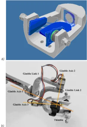
The 5-bar mechanism is linked to the end-effector by a gimble that enables any orientation in the workspace; these rotations are measured by encoders. Fig. 3b shows the gimble, which is made up of two links and three rotational axes that intersect at the fingertip. This implies that only the forces are reflected to the user, without torque components.
The end-effector has a thimble shape and is ergonomically designed to allow realistic object exploration and grasping. The thimble design complies with most of the requirements described in Section 2.2. The geometry of the inside of the thimble is similar to that of the human finger in order to obtain similar touch responses [44] and [45]. The thimble is cone-shaped, narrow at the top and somewhat
thicker at the bottom where the distal phalanx meets the beginning of the middle phalanx. The thimble designed is shown in Fig. 4. This thimble is designed to fit different finger sizes by means of a screw system that adapts to the sides of the finger. Finally, Velcro is used to hold the finger to the thimble. A technique called stereolithography rapid prototyping (stereo-lithography) is used in the production of the thimble. An epoxy resin is used for this process. The total weight of the thimble is 76 grams, which makes it ideal for haptic applications.
a)
b)
Fig. 4. a) The CAD design of the thimble; two screws are used to adapt the thimble to different finger sizes, b) thimble and gimbal system: the three gimbals’ axes intersect at the fingertip in order to
reflect forces without a torque component
4 OPTIMIZATION OF THE 5-BAR MECHANISM
kinematic performance measures such as device workspace, payload capability, and isotropy.
Both, the workspace and performance of the 5-bar mechanism are conditioned by the length of the links [46] and [47]. Link lengths are optimized in accordance with the dextrous workspace and load capabilities required. These conditions are implemented in the global conditioning index in order to optimize the mechanical design.
4.1 Dextrous Workspace
In grasping tasks the dextrous workspace concerns the common space for all fingers. For two-finger grasping this common workspace is determined by the intersection of the areas covered by the 5-bar mechanism in both fingers. As shown in Section 5, the common dextrous workspace for the user’s two fingers is represented as an ellipse of 21×16 cm axes. This common ellipse is also used in 3-finger grasping tasks. The 5-bar mechanism has been optimized to take into account the workspace within this ellipse. Fig. 5 shows the location of the ellipse in the global workspace for the single finger device.
Fig. 5. Global workspace of the 5-bar structure and dexterous workspace in grasping tasks
4.2 Kinematic Optimization
Multi-criteria design optimization is implemented in order to obtain optimal design solutions. A multi-criteria methodology is used that takes into account
the optimization of both GCI and GPImin performance
indexes. This multi-criteria Design Index, DI, is expressed as:
DI=C GCI C GPI1+ 2min, (22)
where Ci is the weight given to each performance
index. Since the physical meaning and the dimensional units of the two performance indicexes are different,
it must be transferred into a common domain, which ranges from 0 to 1 [36]. The GCI is expressed within a common domain as:
GCI GCI GCI
GCI GCI
= −
− min
max min
, (23)
and the GPI index as:
GPI GPI GPI
GPI GPI
min min minmin
max min
min min,
= −
− (24)
Each equation index in Eq. (22) is defined so that a value close to 1 implies good performance of the device. Therefore, the set of lengths with the maximum DI, is the set of optimal lengths.
In Eqs. (23) and (24), GCImax and GPImaxmin
are the maximum values obtained for all possible combinations of lengths, and GCImin and GPIminmin the minimum values, respectively. In Eq. (22), the weight given for GCI is 0.75, and 0.25 for GPI, thereby giving more importance to manipulability than to payload capability. The optimization of the 5-bar mechanism takses place on the previously mentioned ellipse. The discrete parameter space and optimal solutions are shown in Table 1. In order to reduce the apparent inertia of the interface, the actuators of the 5-bar mechanism are located as close as possible to each other, such that the length d (Fig. 2b) is kept constant and equal to 4 cm. It has been observed that link lengths are very similar for optimum GCI, optimum GPI, and optimum DI.
4.3 Device Performance
Link lengths for optimal DI were implemented in the haptic device. Fig. 5 showed the workspace of the 5-bar mechanism and the area in which optimization occurred. The LCI and the minimum of the maximum
force reflected Fmin of all directions for every
point of the workspace are shown in Figs. 6a and b, respectively. The variation of these parameters between close points inside the workspace is an undesirable behaviour.
Table 1. 5-bar parameter space
Parameter Min. [cm] Max. [cm] Step [cm] Total Optimum GCI Optimum GPI Optimum DI
l1 8.0 20.0 1 12 14.0 12.0 13.0
l2 2.0 8.0 0.5 12 6.0 5.0 6.0
l3 2.0 16.0 1 14 11.0 9.0 10.0
l4 2.0 16.0 1 14 4.0 3.0 4.0
l 16.0 22.0 0.5 12 20.0 19.0 20.0
d 4.0 4.0 - - 4.0 4.0 4.0
GCI 0.432 0.407 0.431
GPI 5.17 5.81 5.35
DI 0.971 0.955 0.979
Total discrete samples 7,726,587
selected to ensure an exertable force of 3 N in every direction and at every point of the workspace.
The ellipse of manipulability for several workspace points is shown in Fig. 6c. Ellipses close to a circumference imply similar manipulability in any direction. In contrast, ellipses whose principal axes have different values imply that the manipulability changes depending on the direction of the movement. If the minor ellipse axis is near to zero, it indicates the proximity to a singular point.
Table 2. Main specifications of the haptic device
Property Value
Maximum exertable force * 3 N
Inertia (apparent mass at tip) **
Without encoder gimbal 52 g
With encoder gimbal 128 g
Stiffness ** 1.54 N/mm
Weight of the device 650 g
Bandwidth 8 Hz
*Minimum of the maximum force in all directions for the nominal position. ** Nominal position (midpoint of the workspace).
The specifications of the single finger module are given in Table 2. In the plane of the 5-bar mechanism, the apparent mass in the middle position of the workspace (20 cm from the motor axis) is only 39 g, of which 30% is due to the rotor inertia. The apparent mass about the axis of the serial motor is 52 g. Additionally, 76 g of the thimble weight must be added to the apparent inertia. The mechanical stiffness is 1.54 N/mm and was estimated using Finite Element Analysis (FEA) with Solidworks simulation software, where the stiffness of the device is calculated by simulating an external force at the end-effector and measuring the displacement obtained.
The bandwidth of the proposed system was measured by commanding a sinusoidal trajectory and
a)
b) X
Y
-0.2 -0.1 0 0.1 0.2 0.3 -0,2
-0,1 0 0,1
8 8
8
9
9 8 7 7
7
7 7
6 6 6
6
6
5 5 5
5 5
4 4
4
4 4
3 3
3 2 1 10
c) -0.2 -0.1 0 0.1 0.2 0.3 -0.2
-0.1 0 0.1 0.2
X
Y
Fig. 6. a) LCI of the 5-bar mechanism, b) the minimum of maximum forces (in N) for all directions reflected within the workspace, calculated for a normalized torque of 1 Nm on the
acquiring the encoder position of the motors. These measurements were taken at the plane of the 5-bar mechanism in the middle position of the workspace (20 cm from the motor axis). The results of this experiment are shown in Fig. 7. As can be seen, the resulting frequency (for -3 dB) is approximately 8 Hz. The current bandwidth is limited by the selected actuator planetary gear.
Fig. 7. Measured bandwidth of the proposed 5-bar mechanism; the bandwidth is limited to 8 Hz mainly due to the chosen
actuators
5 STRUCTURAL DESIGN FOR A 2-FINGER HAPTIC DEVICE
A mechanical structure was designed and developed for the two-finger haptic device in order to enable object manipulation within a virtual scenario [48]. The 2-finger haptic device design uses two scalable haptic modules joined by means of an additional redundant axis.
This device was designed specifically for grasping objects with the thumb and index finger. It allows the user to interact with virtual environments and undertake grasping tasks in an easy and comfortable manner. Both modules are connected to the base of the interface by means of an additional and redundant degree of freedom. Fig. 8 shows the 2-finger haptic device designed, where all its actuators are located at the base of the structure in order to lower the inertia.
Fig. 9 shows the reachable and dexterous workspaces covered by the 5-bar mechanism of both fingers. As presented in Section 4, this dexterous workspace can approximate an ellipse of 21×16 cm axes. The redundant DoF significantly increases the workspace of this haptic interface. Fig. 10a shows the dexterous workspace supplied by the first DoF of each module and without the redundant DoF. In Fig. 10b the workspace increases considerably when
the rotating redundant DoF is allowed. The wide workspace obtained by the device’s upper plane reflects an inverted position highly appropriate to certain bimanual manipulation tasks [42] in that it provides the user with a wider collision-free space.
Fig. 8. 2-finger haptic device; the user inserts the thumb and index finger in the corresponding thimbles in order to perform virtual object manipulation; the redundant axis significantly
increases the device workspace
Fig . 9. Dextrous workspace of the 2-finger haptic device
This 2-finger haptic device has been used in several applications for virtual object manipulations. Fig. 11 provides an example of bimanual virtual manipulation where haptic devices are placed in an inverted position. In this case, a box is grasped and raised by one or two hands in order to study the human weight discrimination for virtual manipulation tasks [49].
6 STRUCTURAL DESIGN FOR A 3-FINGER HAPTIC DEVICE
to achieve an optimized workspace. The resulting 3-finger haptic device design is shown in Fig. 12. The two redundant axes enable wrist rotation without causing collisions between modules, and a wide workspace.
Fig. 12. Design of the 3-finger haptic device, which is made up of three haptic devices and two redundant rotational axes
The 3-finger haptic device is designed to allow the user to manipulate the virtual environment using the thumb, index finger, and middle or ring fingers depending on the kind of task to be performed. The middle or ring fingers can be used depending on the hand gesture required by the manipulation [50]. The thumb, index finger, and middle fingers are used for performing precise manipulations such as writing. In contrast, the thumb, index finger, and ring finger are more suitable for powerful manipulations such as carrying a suitcase. This second configuration is more stable and adequate for handling heavy loads. The middle or ring finger is selected according to the
Fig. 11. Example of bimanual manipulation using a 2-finger haptic device for each hand; the set-up is optimized for grasping virtual objects; the same object is uni- or bi- manually grasped
a)
b)
Fig. 10. a) 3D workspace of the 2-finger haptic device without a redundant DoF; b) 3D workspace of the 2-finger haptic device with
a redundant DoF
hand gesture required [51] and [52] and based on the precision/power needed for the task or the prismatic/ circular manipulation.
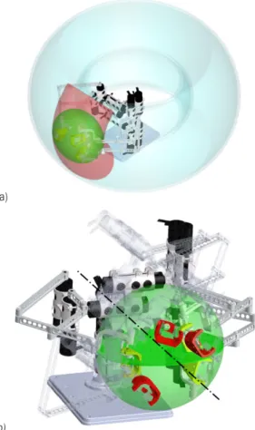
A large workspace is obtained for the 3-finger haptic device. It has an almost toroidal shape, as shown in Fig. 13a. The first redundant DoF enables rotation with respect to the device base. It defines the toroidal area and allows the user’s hand long movements. The second DoF represents the rotation of the user’s wrist and it prevents collisions between the module links when the human wrist rotates. This movement is shown in Fig. 13b, where the optimal ellipse achieved by the 5-bar mechanism rotates around the redundant DoF.
a)
b)
Fig. 13. a) Effective workspace of the 3-finger device with two redundant DoF for grasping tasks; b) The second redundant DoF
prevents collisions between the modules
The mechanical design described for 2-finger and 3-finger haptic devices may not be suitable when extended to four and five fingers. The main problems concern the concentration of actuators in the device base and the thimble design four and five fingers, 14 and 17 actuators are required, respectively. This high number of actuators cannot be properly located close
to the device base without a significant increase in collisions and, therefore, an increase in the device’s inertia.
7 CONCLUSIONS
This paper describes the mechanical design of a two- and three- finger haptic device. The design was optimized for grasping tasks in which virtual objects are manipulated by one or two hands. The main requirements considered for the mechanical design of multifinger haptic devices have been: low inertia, the force reflected, scalability, and an adjustable and ergonomic thimble.
The main contribution of this paper concerns the design of multifinger haptic devices to achieve a proper workspace. An optimized, scalable mechanical structure for one finger has been defined. Specifically, we ensure a proper workspace for the resultant multifinger haptic device by means of an addition of a redundant axis for joining modules. As we have shown, one or two redundant axes are adequate for providing a proper workspace for 2-finger or 3-finger haptic interfaces. These redundant axes extend the workspace area and prevent link collisions when hand orientation changes.
This solution offers a significantly broader workspace in comparison with the use of several single-finger haptic interfaces together, while being similar in complexity. In contrast, certain multi-fingered haptic devices exist that offer a larger workspace, but at the expense of greater complexity, since a robot-like device must be used to transport the haptic device.
8 ACKNOWLEDGEMENTS
This work has been partially funded by the Spanish “Ministerio de Ciencia e Innovación” under the projects “TEMAR” (DPI 2009-12283) and “DAVARBOT” (DPI 2011-22513), the European Commission Immersive multi-modal interactive presence (IMMERSENCE) under Grant FP6-IST-027141, the “Personal Investigador en Formación” by UPM, and the Andalusia Regional Government under the Grant FPDU 2008 co-financed by the European Union through the European Regional Development Fund (ERDF).
9 REFERENCES
Computer Graphics Applications, vol. 17, no 5, p. 6-10, DOI:10.1109/MCG.1997.1626171.
[2] Škorc, G., Zapušek, S., Čas, J., Šafarič, R. (2010). Virtual user interface for the remote control of a nano-robotic cell using a haptic-device. Strojniški vestnik – Journal of Mechanical Engineering, vol. 56, no. 7-8, p. 423-435.
[3] Peer, A., Buss, M. (2008). A New admittance-type haptic interface for bimanual manipulations. IEEE/ ASME Transactions on Mechatronics, vol. 13, no. 4, p. 416-428, DOI:10.1109/TMECH.2008.2001690.
[4] Waldron, K.J., Tollon, K. (2003). Mechanical characterization of the immersion corp. haptic,
bimanual, surgical simulation interface. 8th
International Symposium on Experimental Robotics, vol. 5, p. 106-112.
[5] Ferre, M., Galiana, M., Wirz, R., Tuttle, N. (2011). Haptic device for capturing and simulating hand manipulation rehabilitation. IEEE/ASME Transactions on Mechatronics, vol. 16, no 5, p. 808-815, DOI:10.1109/TMECH.2011.2159807.
[6] Strolz, M., Groten, R., Peer, A., Buss, M. (2011). Development and evaluation of a device for the haptic rendering of rotatory car doors. IEEE Transactions on Industrial Electronics, vol. 58, no. 8, p. 3133-3140, DOI:10.1109/TIE.2010.2087292.
[7] Coles, T.R., Meglan, D., John, N.W. (2011). The role of haptics in medical training simulators: A survey of the state of the art. IEEE Transactions on Haptics, vol. 4, no. 1, p. 51-66, DOI:10.1109/TOH.2010.19.
[8] Raju, G.J., Verghese, G.C., Sheridan, T.B. (1989). Design issues in 2-port network models of bilateral remote teleoperatio. IEEE International Conference on Robotics and Automation, p. 1317-1321.
[9] Yokokohji, Y., Yoshikawa, T. (1992). Bilateral control of master-slave manipulators for ideal kinesthetic
coupling-formulation and experiment. IEEE
Transactions on Robotics and Automation, vol. 10, no. 5, p. 605-620, DOI:10.1109/70.326566.
[10] Lawrence, D.A. (1993). Stability and transparency
in bilateral teleoperation. IEEE Transactions on
Robotics and Automation, vol. 9, no. 5, p. 624-637, DOI:10.1109/70.258054.
[11] Melder, N., Harwin, W.S. (2005). Force shading and bump mapping using the friction cone algorithm.
Eurohaptics Conference and Symposium on Haptic Interfaces for Virtual Environment and Teleoperator Systems, p. 573- 575, DOI:10.1109/WHC.2005.58. [12] Droll, J.A., Hayhoe, M.M., Triesch, J., Sullivan,
B.T. (2005). Task demands control acquisition and storage of visual information. Journal of Experimental Psychology: Human Perception and Performance, vol. 31, no. 6, p. 1416-1438, DOI:10.1037/0096-1523.31.6.1416.
[13] CyberGlove Systems LLC. CyberGlove II, CyberTouch, CyberGrasp, and CyberForce California, from http://www.cyberglovesystems.com, accesed on 2012-03-30.
[14] Kohno, Y., Walairacht, S., Hasegawa, S., Koike, Y., Sato, M. (2001). Evaluation of two-handed multi-finger haptic device SPIDAR-8. Precision and Intelligence Laboratory, Tokyo Institute of Technology. Nagatsuta, Yokohama.
[15] Endo, T., Kawasaki, H., Mouri, T., Ishigure, Y., Shimomura, H., Matsumura, M., Koketsu, K. (2011). Five-fingered haptic interface robot: HIRO III. IEEE Transactions on Haptics, vol. 4, no. 1, p. 14-27, DOI:10.1109/TOH.2010.62.
[16] Kawasaki, H., Mouri, T., Osama, M., Sugihashi, Y., Ohtuka, Y., Ikenohata, S., Kigaku, K., Daniulaitis, V., Hamada, K. and Suzuki, T. (2005). Development of Five-Fingered Haptic Intereface: HIRO II.
Proceedings of ICAT, Christchurch, p. 209-214, DOI:10.1145/1152399.1152437.
[17] CyberGlove Systems LLC. User’s Guides, from http:// cyberglovesystems.smartsupportapp.com/subjects/ user-guides, accesed on 2012-03-30.
[18] Raytheon Company. Big Arm, from http://www.
raytheon.com/businesses/rids/businesses/gis/strategic_ solutions/robotics/bigarm/index.html, accessed on 2012-03-30.
[19] Lee, S.S., Lee, J.M. (2003). Design of a general purpose 6-DOF haptic interface. Mechatronics, vol. 13, p. 697-722, DOI:10.1016/S0957-4158(02)00038-7.
[20] O’Malley, M., Goldfarb, M. (2002). The effect of force saturation on the haptic perception of detail. IEEE/ ASME Transactions on Mechatronics, vol. 7, no. 3, p. 280-288, DOI:10.1109/TMECH.2002.802725.
[21] Guthart, G.S., Salisbury, J.K. (2000). The IntuitiveTM telesurgery system: overview and application. IEEE International Conference on Robotics & Automation, p. 618-621.
[22] Moog Inc. Moog Simodont Dental Trainer, from
http://www.moog.com/literature/ICD/Moog-Haptics-SimodontDentalTrainer-Datasheet-en.pdf, accessed on 2012-03-30.
[23] Fischer, P., Daniel, R., Siva, K.V. (1990). Specification and design of input devices for teleoperation.
Proceedings of the 1990 IEEE International Conference on Robotics and Automation, Cincinnati, p. 540-545. [24] Hayward, V. Astley, O.R. (1996). Performance
measures for Haptic Interfaces. 7th International Symposium in Robotics Research, p. 195-207.
[25] Yoshikawa, T. (1991). Translational and rotational manipulability of robotic manipulators. Industrial Electronics Conference Proceedings, p. 1170.
[26] Gosselin, C., Angeles, J., (1991). Global performance index for the kinematic optimization of robotic manipulators. Journal of Mechanisms, Transmissions, and Automation in Design, vol. 113, p. 220-226. [27] Stocco, L., Salcudean, S.E., Sassani, F. (1998). Fast
constrained global minimax optimization of robot parameters. Robotica, vol. 16, no. 6, p. 595-605, DOI:10.1017/S0263574798000435.
parallel manipulators. Proceedings of the 1996 IEEE International Conference on Systems, Man and Cybernetics, Beijing, p. 1483-1488.
[29] Merlet, J.P. (2006). Jacobian, manipulability, condition number, and accuracy of parallel robots. Journal of Mechanical Design, Transactions of the ASME, vol. 128, p. 199-206, DOI:10.1115/1.2121740.
[30] Liu, X.J., Wang, J., Pritschow, G. (2006). Kinematics, singularity and workspace of planar 5R symmetrical
parallel mechanisms. Mechanism and Machine
Theory, vol. 41, no. 2, p. 145-169, DOI:10.1016/j. mechmachtheory.2005.05.004.
[31] Unal, R., Kiziltas, G., Patoglu, V. (2008). A multi-criteria design optimization framework for haptic interfaces. Symposium on Haptics Interfaces for Virtual Environment and Teleoperator Systems Proceedings, p. 231, DOI:10.1109/HAPTICS.2008.4479949.
[32] Asada, H. (1983). Geometrical representation of manipulator dynamics and its application to arm design. Journal of Dynamic Systems, Measurement and Control, Transactions of the ASME, vol. 105, no. 3, p. 131-135.
[33] Yoshikawa, T. (1985). Dynamic manipulability of robot manipulators. Journal of Robotic Systems, vol. 2, no. 1, p. 113-124.
[34] Wall, S.A., Harwin, W. (2001). A high bandwidth interface for haptic human computer interaction.
Mechatronics, vol. 11, no. 4, p 371-387, DOI:10.1016/ S0957-4158(00)00024-6.
[35] Brooks, T.L. (1990). Telerobotic response requirements.
Systems, Man and Cybernetics, Conference Proceedings of IEEE International Conference, p.113-120.
[36] Lee, J.H., Yi, B.J., Oh, S.R., Suh, I.H. (2001). Optimal design and development of a five-bar finger with redundant actuation. Mechatronics, vol. 11, p. 27-42, DOI:10.1016/S0957-4158(99)00089-6.
[37] Castejón, C., Carbone, G., Prad, J.C.G., Ceccarelli, M. (2010). A multi-objective optimization of a robotic arm for service tasks. Strojniški vestnik – Journal of Mechanical Engineering, vol. 56, no. 5, p. 316-329. [38] Kucuk, S., Bingul, Z. (2006). Comparative study
of performance indices for fundamental robot manipulators. Robotics and Autonomous Systems, vol. 54, no. 7, p. 567-573, DOI:10.1016/j.robot.2006.04.002. [39] Ryu, D., Song, J.B., Cho, C., Kang, S., Kim, M.
(2010). Development of a six DOF haptic master for teleoperation of a mobile manipulator. Mechatronics, vol. 20, no. 2, p. 181-191, DOI:10.1016/j. mechatronics.2009.11.003.
[40] Yoon, J., Ryu, J. (2001). Design, fabrication, and evaluation of a new haptic device using a
parallel mechanism. IEEE/ASME Transactions
on Mechatronics, vol. 6, no. 3, p. 221-233, DOI:10.1109/3516.951360.
[41] Stocco, L.J., Salcudean, S.E., Sassani, F. (2001). Optimal kinematic design of a haptic pen. IEEE/ASME
Transactions on Mechatronics, vol. 6, no. 3, p. 210-220, DOI:10.1109/3516.951359.
[42] Garcia-Robledo, P., Ortego, J., Ferre, M., Barrio, J., Sanchez-Uran, M.A. (2011). Segmentation of bimanual virtual object manipulation tasks using multifinger haptic interfaces. IEEE Transactions on Instrumentation and Measurement, vol. 60, no. 1, p. 69-80, DOI:10.1109/TIM.2010.2065690.
[43] Monroy, M., Oyarzabal, M., Ferre, M., Campos, A., Barrio, J. (2008). MasterFinger: Multi-finger haptic interface for collaborative environments. Proceedings of the EuroHaptics, vol. 5024, p. 411-419.
[44] Ferre, M., Galiana, I., Aracil, R. (2011). Design of an affordable thimble-like sensor for haptic application based on force-sensing resistors. Sensors, vol. 11, p. 11495-11509, DOI:10.3390/s111211495.
[45] Monroy, M., Ferre, M., Barrio, J., Eslava, V., Galiana. I. (2009). Sensorized thimble for haptic applications.
IEEE International Conference on Mechatronics, p. 1-6, DOI:10.1109/ICMECH.2009.4957201.
[46] Giachritsis, C.D., Ferre, M., Barrio, J., Wing, A. (2011). Unimanual and bimanual weight perception of virtual objects with a new multi-finger haptic interface.
Brain Research Bulletin, vol. 85, no. 5, p. 271-276, DOI:10.1016/j.brainresbull.2011.03.017.
[47] Cervantes-Sánchez, J.J., Hernández-Rodríguez, J.C., Rendón-Sánchez, J.G. (2000). On the workspace, assembly configurations and singularity curves of the
RRRRR-type planar manipulator. Mechanism and
Machine Theory, vol. 35, p. 1117-1139, DOI:10.1016/ S0094-114X(99)00061-0.
[48] Galiana, I., Bielza, M., Ferre, M. (2010). Estimation of normal and tangential manipulation forces by using
contact force sensors. Lecture Notes in Computer
Science Springer, Eurohaptics, vol. 6191, p. 65-72. [49] García-Robledo, P., Ortego, J., Barrio, J., Galiana,
I., Ferre, M., Aracil, R. (2009). Multifinger haptic interface for bimanual manipulation of virtual objects interaction between two hands and virtual objects with MasterFinger. IEEE International Workshop on Haptic Audio Visual Environments and Games, Lecco, p. 30-35.
[50] Liu, X.J., Wang, J., Pritschow, G. (2006). Performance atlases and optimum design of planar 5R symmetrical
parallel mechanisms. Mechanism and Machine
Theory, vol. 41, p. 119-144, DOI:10.1016/j. mechmachtheory.2005.05.003.
[51] Cobos, S., Ferre, M., Sánchez-Urán, M.A., Ortego, J., Aracil, R. (2010). Human hand descriptions and gesture recognition for object manipulation. Computer Methods in Biomechanics and Biomedical Engineering, vol. 13, no. 3, p. 305-317, DOI:10.1080/10255840903208171. [52] Cutkosky, M.R. (1989). On grasp choice, grasp models,
![Fig. 1. Examples of multi-fingered haptics devices; a) Two Phantoms [12]; b) CyberGrasp [13]; c) Spydar [14]; and d) Hiro III [15]](https://thumb-us.123doks.com/thumbv2/123dok_es/6844073.837183/1.878.112.795.887.1049/examples-multi-fingered-haptics-devices-phantoms-cybergrasp-spydar.webp)