Alta Velocidad Ferroviaria en California
(USA): Te/cera Parte (III)
Fresno-Los Ángeles-San Diego
High Speed Railway ¡n California (USA):
Third Part (III)
Fresno-Los Angeles-San Diego
MANUEL DÍAZ DEL RIO JÁUDENES (•), LUIS FORT LÓPEZ-TELLO (••) y CARMEN FORT SANTA-MARÍA
RESUMEN Este artículo, tercera parte de la serie que describe la red de Alta Velocidad Ferroviaria de California (CHSRS), se ocupa de la línea Fresno-Los Angeles Airport-San Diego Airport, con el trazado propuesto en la Alternativa "Missions Trail" del Proyecto FARWEST, caracterizada por el paso directo de las montañas de Tehachapi, mediante dos grandes túne-les de 27,5 Km (17 mile) y 25,6 Km (15,9 mile) de longitud. También por el emplazamiento de la estación terminal de Los Angeles, junto al Aeropuerto Internacional de Los Angeles y la sustitución de la circunvalación ferroviaria de la aglomera-ción urbana de Los Angeles, a través de "Inland Empire", por el ramal Anaheim-Riverside, que da acceso a esa región, y que es cabecera de la futura "Dessert Express" a Las Vegas.
ABSTRACT The third ofa series describing the California High Speed Railway (CHSRS), this article refers to the Fresno-Los
Angeles Airport-San Diego Airport Une, with the alignment as proposed in the "Missions Trail" Alternative of the FARWEST Project, characterized by the direct Tehachapi mountain pass through two large tunnels 27.5 Km (17 miles) and 25.6 Km (15.9 miles) long and also to the siting ofthe Los Angeles terminal station next to the Los Angeles International Airport and the replacement of the Los Angeles urban conglomeration railway by-pass through "Inland Empire", by the Anaheim-Riverside branch providing access to that región and which is the head ofthe future "Desert Express" to Las Vegas.
1. INTRODUCCIÓN
La Línea Fresno-Los Angeles-San Diego del Proyecto FAR-WEST (MISSIONS TRAIL Alternative) tiene una longitud de 502 Km (312 mile), (más 55 km del ramal a Riverside)
for-l INTRODUCTION
^ T
-TS
*^?T"
*
-^T
T T
Iff-T 5 *
«
^~
T£T
i¡
\
s
5
" •*• • f l 1- •• • - -H•
—
3
«uI»
A l ™ 0-™
*
Mg
™ fl¡s
u • _
;
wr"
p -N* • »3
™ - Jt¡
A¡¡
2
MI - I
n-•
«
*f*a-M ^ _ É —
'
-—
\
m • p • m • fl-It
•
r n»
f f c
™
-™
i(
*
¡*
ti • i vaP»
»
J
'*
•j ™t"
•^
• 1-
=„
*
H ÉM P" UJ •i
!
.. ..
fl"
. " . .
„ " „
- Ww
^
3
A
• L . .
1
-
J l n J.,.
1 — — p —
i!
-A n ™
.."..
i fl •p ^ ^ ^
-fl
5
A1=
<n fl I hN * —
™;
• •
B
—
¡ N
-• 1 * _
• V
I'
b -• -• p1 . . *
• • fl m '•
•j
Hs
•it
-P fl
^
MI-~
• fl"
s
« f t * £ f l P A j
TABLA 1. Distancia, Velocidad y Tiempos de recorrido entre las principales estaciones HSR
/Distance, Speed and Journey times between the main HSR stations.
mando parte de ella las secciones I: Fresno-Bakersfield de 157 km (98 mile), IV: Bakersfield-Los Angeles (Airport) de 166 Km (103 mile) y VI+VIII Los Angeles (Airport)-San Diego (Air-port) de 179 Km (111 mile), con las estaciones de Alta Veloci-dad (HSR Stations) intermedias, Bakersfield, Anaheim y Oce-anside y las terminales de Fresno ( pk 0 de la red de alta velocidad), Los Angeles (Airport) y San Diego (Airport).
El trayecto Fresno-Bakersfield de esta Alternativa, con-cuerda con la Sección I del Initial Central Valley de la red (CHSRS), manteniendo al desarrollarse en el Central Valley el carácter de columna vertebral de la red planificada por la Au-toridad ferroviaria de la Alta Velocidad de California (CHSRA). No obstante, la ubicación de la estación de Fresno se desplaza hacia el suroeste respecto a la prevista, llevándola fuera del centro urbano para poder convertirla en la gran ter-minal central de alta velocidad de California, origen de las tres líneas principales de ésta:
- LAV Fresno-San Francisco ("Golden Gate Alternative", descrita hasta la estación de San Francisco Airport, en la segunda parte del anterior artículo de este mismo tí-tulo general)- Sacramento Roseville ("Bay Crossing Al-ternative", que será tratado en el artículo final de esta serie, por el carácter especialmente importante que tiene, con la espectacular obra de ingeniería que es el cruce de la Bahía).
sections I: Fresno- Bakersfield, 157 km (98 miles), IV: Ba-kersfield-Los Angeles (Airport), 166 Km (103 miles) and VI+VIII Los Angeles (Airport)-San Diego (Airport), 179 Km (111 miles), with the intermedíate High Speed (HSR) Bakersfield, Anaheim and Oceanside Stations and the ter-mináis of Fresno (P.K. 0 km of the high speed system), Los Angeles (Airport) and San Diego (Airport).
The Fresno-Bakersfield alignment of this Alterna-tive coincides with Section I of the (CHSRS) system's Initial Central Valley, keeping the nature of backbone of the system planned by the California High Speed Railway Authority (CHSRS) on running in the Central Valley. Nevertheless, the site of Fresno station is moved to the south-west from the one planned, and is taken outside the city centre to become the grand central Cal-ifornia High Speed terminal, the origin of its three main Unes:
- LAV Fresno-Los Angeles (Airportí-San Diego (Airport) "Missions Trail Alternative" (cuya descripción es objeto del presente artículo).
- LAV Fresno-Sacramento Roseville ("Stockton Arch Al-ternative", por el lado Este de la Bahía, que será des-crita en otro artículo).
2. TRAYECTO FRESNO-BAKERSFIELD
En este trayecto, sin especiales problemas constructivos, se al-canzan las velocidades de recorrido más altas de la red, con una media de 327 Km/h (202 mph) y un tiempo de viaje infe-rior a media hora (Tabla 1).
En la primera columna de la Tabla 2 se reflejan las princi-pales características de este tramo, de las que se mencionan las siguientes:
- Se proyectan dos PAETs de 2,3 Km de longitud, inter-medios: Corcoran-Tulare (pk 55+000), con acceso desde la 137 Road y Wasco-Famoso (pk 125+000), con acceso desde la multilane 46 Road, además de los dos situados en las estaciones de Fresno y Bakersfield.
- Fresno-Los Angeles HSL (Airportí-San Diego
(Air-port) "Missions Trail Alternative" (which is being des-cribed in this article).
- Fresno-Sacramento Roseville HSL ("Stockton Arch Alternative", on the Bay's East side, which will be described in a further article).
2. FRESNO-BAKERSFIELD AUGNMENT
With no special construction problems in this alignment, the highest running speeds in the system are reached with an average of 327 Km/h (202 mph) and less than half an hour's journey time (Table 1).
The first column of Table 2 shows the main characteris-tics ofthis section, of which the following are mentioned:
- Two 2.3 Km long, intermedíate TSAPs (post of pas-sing and stabling train) are designed: Corcoran-Tu-lare (P.K 55+000), with access from Road 137 and Wasco-Famoso (P.K. 125+000), with access from mul-tilane Road 46, apart from the two located in the Fresno and Bakersfield stations.
FIGURA 1. Trazado línea HSR Fresno-Bakersfield /Fresno - Fresno-Bakersfield HSR Une
alignment.
-^
B¡
---.-?£?£-:._"
*
- /
- . *
-J I _
—
"%
te-n a
• • - •
s
' - • •
t
-\
> * id
f
r 1 - ^ . L
i a
i r ~ T
i
T~S~
¡ — —La traza de esta línea HSR discurre en el interior del corredor, anexo a San Joaquín Valley, limitado por la Hwy 99 al Este y por la multilane road 43 y ef ferro-carril Fresno-Bakersfield al Oeste, sobre siete via-ductos (uno con un tramo en arco de tablero interme-dio de 200m de luz) sobre los ríos Kings River, Kaweah River, Elk Bayon,Tule River, Friant Kern Canal, y pasos sobre carreteras estatales y secunda-rias y sobre los ferrocarriles a Visalia, Tehachapi y Río Bravo (Figura 1).
El trazado, prácticamente todo en terraplén de pequeña a mediana altura para permitir el paso de ríos, carrete-ras y ferrocarriles que discurren por el Valle del río San Joaquín, con un movimiento de tierras de 43,82 Mm3, de
los que 42,22 Mm3 de déficit.
Se propone las inmediaciones de la localidad de Corco-ran para emplazamiento de las instalaciones de obra iniciales de la red, como tiene previsto la CHSRA, con trámites avanzados de disponibilidad de terrenos, dado su posición centrada en este trayecto, con acceso al fe-rrocarril y a la 43 road que comunican actualmente Fresno con Bakersfield.
3. TRAYECTO BAKERSFIELD-LOS ANGELES (AIRPORT)
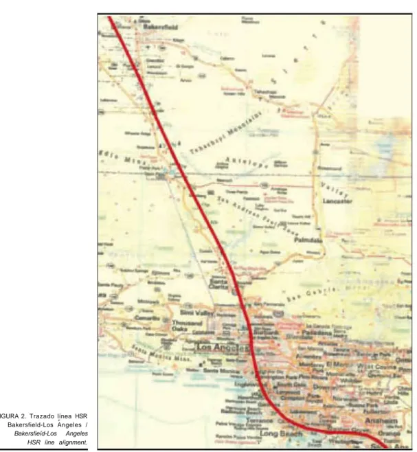
Este trayecto, en el Proyecto Farwest, se plantea con un tra-zado valiente, con dificultades constructivas, pero directo, es-pecialmente concebido para formar parte de una línea de alta velocidad, la comercialmente más importante de la red, por la concentración de población a la que dará servicio cuando esté operativa (Figura 2).
Igualmente, la Tabla 2 sintetiza en su quinta columna las principales características de este trayecto, identificada como Section IV de la CHSTR Se destacan a continuación, las si-guientes:
- El 58% de la longitud de este trayecto discurre en túnel, atravesando las montañas de Tehachapi (Figura 2) me-diante dos grandes túneles, TU 1 L=27,5 Km en su ver-tiente norte y TU 2 L=25,6 Km en su verver-tiente sur, adentrándose en "Angeles National Forest", que no obs-tante sus longitudes presentan fuertes inclinaciones. El TU 1 en dirección Los Ángeles, con rampa de 16,9 milé-simas, baja la velocidad media de marcha a 80 Km/h (con locomotoras de última generación previstas para este proyecto con potencia de diseño para velocidad má-xima de 380 Km/h) y 21 min de tiempo de recorrido en túnel. En este mismo sentido de marcha, el TU 2 con pendiente de 21,9 milésimas, velocidad media de mar-cha de 130 Km/h y 12 min de recorrido en túnel, hace de este tramo, uno de los más característicos y difíciles de la red y a su vez de los de mayor interés de puesta en operación (Figura 3).
- Potencial geotérmico
Al igual que en el tramo Oroloma-Gilroy descrito en el ar-tículo anterior de esta serie, la construcción de este Trayecto Bakersfield-Los Ángeles, en el tramo Metler-Valencia, puede aportar una potenciación de impactos positivos en la excava-ción de dos grandes túneles para atravesar las montañas de Tehachapi, con la utilización del potencial geotérmico de este macizo montañoso, a través de las aguas subterráneas drena-das por los túneles.
En función de las alturas medias de montera, la longitud de los túneles y mediante correlación con los valores estimados en los túneles del Trayecto Fresno-Gilroy. se deduce un
poten-- This HSR line's alignment runs inside the corridor,
next to San Joaquín Valley, limited by Hwy 99 to the East and by multilane road 43 and the Fresno-Bakersfield railway to the West, over seven viaducts (one with a section of a 200 m span inter-medíate arch deck over the Kings River, Kaweah Ri-ver, Elk Bayon, Tule RiRi-ver, Friant Kern Canal and overpasses State and secondary roads and the rail-way s to Visalia,Tehachapi and Río Bravo (Figure 1).
- Practically all on small to médium height embank-ment to allow for rivers, roads and railways running through the San Joaquín river Valley to pass under, with 43.82 Mm3 earthworks ofwhich 42.22 Mm3 are
déficit.
- The vicinity of Corcoran is proposed for siting the sys-tem's initial construction work facilities, as the CHSRA has provided for, with advanced negotiations on land availability, in view of its central position on this alignment, with access to the railway and to the 43 road which currently connect Fresno to Bakers-field.
3. BAKERSFIELD-LOS ANGELES (AIRPORT) ALIGNMENT
In the Farwest Project, this route is proposed with a daring alignment with construction problems, but direct, especially conceived to form part of a high speed Une, the most com-mercially important in the system because ofthe population concentration which it will service when operative (Figure 2).
Likewise, in its fifth column, Table 2 synthesizes the main characteristics of this alignment, identified as Section IV of the CHSTP. The following may be high-lighted:
- 58% of this alignment's length is tunneled, through the Tehachapi mountains (Figure 2) through two large tunnels, TV 1 L=27.5 Km on its north side and TU 2 L=25.6 Km on its south side, entering the "An-geles National Forest", which, despite their lengths, are steeply sloping. In the Los Angeles direction, TU1, with a slope of 16.9 thousandths, reduces the average running speed to 80 Km/h (with the latest generation of locomotives provided for this Project with a design rating for a máximum speed of 380 Km/h) and 21 min journey time in the tunnel. TU 2, in this same running direction with a gradient of 21.9 thou-sandths, average running speed of 130 Km/h and 12 min journey time in the tunnel, makes this section one ofthe most characteristic and difficult on the sys-tem and, in turn, of the greatest interest as to its co-ming into operation (Figure 3).
- Geothermal energy
As in the Oroloma-Gilroy section, described in the previous article of this series, the construction of this Bakersfield-Los Ángeles route, in the Metler-Valencia section, may strengthen positive impacts in excavating the two large tunnels to run through the Tehachapi mountains, by using geothermal energy from this moun-tain massif through the groundwater drained off by the tunnels.
FIGURA 2. Trazado línea HSR Bakersfield-Los Angeles /
Bakersfieíd-Los Angeles HSR íine aíignment.
cial geotérmico eficaz de 6,6 Mwt, según se especifica a conti-nuación:
• TU 1 L= 27,5 km Montera media M = 350 m. • TU 2 L= 25,6 km Montera media M = 350 m.
Valores medios TUl, TU2 y TU3 del Trayecto Fresno-Gilroy:
ZTU (1 a 3) L= 44,6 Km Montera media M= 350 m. Caudal suma medio aguas en portales de túneles 361,6 1/s. Potencial geotérmico suma medio eficaz 5,53 Mwt. Ratio caudal/frente drenantec 23,16 1/s km2.
Ratio potencial geotérmico/frente drenante
0,354 Mwt/km2.
Túneles Trayecto Bakersfield-Los Angeles. TUl (Tehachapi Norte).
Caudal medio aguas drenadas: Q «»230 1/s. Potencial geotérmico eficaz: Wt= 3,40 Mwt.
geothermal energy of 6.6 Mwt can be inferred, as specified below:
* TU 1 L= 27.5 km Average overburden M = 350 m.
• TU 2 L= 25.6 km Average overburden M = 350 m.
Average valúes TUl, TU2 and TU3 on the Fresno-Gilroy Aíignment:
2TU (1 to 3)1= 44.6 Km Average overburden M = 350 m. Average total water flow at tunnel portáis
361.6 lis. Total effective geothermal energy 5.53 Mwt. Flow Idrain front ratio 23.16 lis km2.
Geothermal energy I drain front ratio
0.354 Mwt/km2.
Bakersfield-Los Angeles Aíignment Tunnels. TUl (Tehachapi North).
LxM= 3,24 km2
LxM= 9,60 km2 Wt=3990kw
LxM= 2.76 km2 Montera media
TU2 (Tehachapi Sur).
Caudal medio aguas drenadas: Q «»210 1/s. Potencial geotérmico eficaz: Wt= 3,20 Mwt.
Línea Golden Gate (Túneles largos):
• TU 1 L= 16,2 km Montera < M = 200 m (+ 7,16%o). • TU 2 L= 19,2 km Montera > M = 500 m.(4 km al
+2.75%0 y 10,45 km al -10,45%o).
• TU 3 L= 9,2 km Montera M = 300 m.( al -6,5%0).
Potencial geotérmico.
TU1 Q » 74,2 1/s Wt= 690 Kw
TU2 Q = 30,71/s | Wt=350Kw Q= 21,36 lis
Q » 182,9 1/s J Wt= 3640 Kw
TU3 Q m 73.8 1/s Wt= 850 Kw 361,611 s 5.530 kw
350 m.
8,111 s 124 Kw I Km 354 Kw I Km2
Línea Missions Trails:
a) Bakersfield - Los Ángeles (Túneles largos)
• TU 1 L= 27,5 km Montera < M = 350 m. (+16,9%o) LxM= 9,62 km2 Tehachapi
• TU 2 L= 25,6 km Montera < M = 500 m. (-21,9%o) LxM= 8.96 km2
Potencial geotérmico: 6.577 kw 18,58 km2
• TU 3 L= 6,5 km Montera M = 50 m. (al 0,0%o) LxM= 0,33 km2
• TU 4 L= 16,1 km Montera M = 100 m. (al -ll,6%o) LxM= 1,61 km2
• TU 5 L= 12,2 km Montera M = 50 m. ( al -5,8%0)
LxM= 0.61 km2
Potencial geotérmico: 903 kw 2,55 km2
b) Anaheim - San Diego
c) TU 3 L= 12,3 km Montera M = 100 m. (+y -%o) LxM= 1,23 km2
d) TU 8 L= 11,3 km Montera M < 50 m. (+y -%o) LxM= 0,57 km2
e) TU 5 L= 12,2 km Montera M = 50 m. (+y -%o) LxM= 0.38 km2
Potencial geotérmico: 772 kw 2,18 km2
Total 23,31 km2 x 354 kw/km2-8.250 Kw
— También en este trayecto, con traza próxima y paralela a la Hwy 5, se proyectan los túneles TU 3 (6,5 Km), TU 4 (16,1 Km) y TU 5 (12,2 Km), para seguir atravesando el primero de ellos, de forma respetuosa con el entorno natural, el "Angeles National Forest". El TU 4 pasa bajo Los Angeles Aqueduct, Six Flag Magic Mountain, la po-blación de Santa Clarita y la Hwy 5 en su entronque con la Hwy 14. Los TU 3 y TU 4 tienen rasante con pendien-tes mínimas para permitir la evacuación de las aguas subterráneas por ellos drenadas, con lo que la velocidad media de marcha se recupera a niveles superiores a los 265 Km/h. El TU 5 discurre bajo Beverly Hills ya en plena aglomeración urbana de Los Angeles, con su por-tal norte en Burbank. La rasante ha aumentado la
pen-TU2 (Tehachapi South).
Average drained water flow: Q •* 210 lis. Effective geothermal energy: Wt= 3.20 Mwt.
Golden Gate Line (Long tunnels):
• TU 1 L= 16.2 km Overhurden <M = 200m(+ 7.16%o) • TU 2 L= 19.2 km Overhurden > M = 500 m. (4 km
at +2.75%o and 10.45 km at -10.45%c).
• TU3 L= 9.2 km Overhurden M= 300m.(at-6.5%>).
Geothermal energy. TU1
TU2
TU3
Q «74.2 lis Q~30.7l/s
Q » 182.9 lis Q~73.8lls
361.611s
8.1 lis Missions Trails Line:
Wt= 690 Kw
Wt= 350 Kw
Q= 21.36 lis Wt= 3640 Kw
W,= 850 Kw 5.530 kw
124 Kw I Km
LxM= 3.24 kr, LxM=9.60kr. Wt=3990kw
LxM=2.76km2
Average overhurden 350m. 354 Kw I Km2
a) Bakersfield-Los Angeles (Long tunnels)
• TU 1 L= 27.5 km Overhurden < M= 350 m. (+ 16.9%c)
LxM= 9.62 km2 Tehachapi
• TU 2 L= 25.6 km Overhurden < M= 500 m. (-21.9%c)
LxM=8.96km2
50 m. (at Omcc)
'lü)
Geothermal energy: 6.577kw 18.58 km2
• TU 3 L= 6.5 km Overhurden M
LxM= 0.33 km2
• TU 4....L= 16.1 km Overhurden M = 100 m. (at -111
LxM= 1.61 km2
• TU 5....L= 12.2 km Overhurden M = 50 m. (at -5.8%o)
LxM= 0.61 km2
Geothermal energy: 903 kw ..2.55 km2
b) Anaheim San Diego
c) TU 3 L= 12.3 km Overhurden M •• 100 m. (+and -%>) LxM= 1.23 k m
d) TU 8 L= 11.3 km Overhurden M < 50 m. (vy -%>) LxM=0.57km2
e) TU 5 L LxM= 0.38 k
12.2 km Overhurden M = 50 m. (+y -%>) m
Geothermal energy: 772 kw ..2.18 kr.
Total 23.31 kr. • 354 kw I km2 » 8,250 Ku
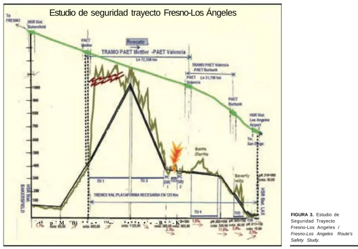
Estudio de seguridad trayecto Fresno-Los Ángeles
-•* p ' M "fti * * » • ™«- * • * * • • ' « - B * ^ - K
FIGURA 3. Estudio de Seguridad Trayecto Fresno-Los Angeles /
Fresno-Los Angeles Route's Safety Study.
diente hasta 11,6 milésimas en el tramo a cielo abierto entre San Fernando y Burbank, reduciéndose ésta a la mitad 5,8 milésimas en el interior del túnel y alcan-zando la velocidad media de marcha 325 Km/h. -Un túnel de carácter urbano, TU 6, de 8,4 Km de
longi-tud, se proyecta desde Culver City, bajo Huntington Park e Inglewood, para la implantación de la Estación más importante de la red Los Angeles (Airport) HSR Station, frente al Aeropuerto Internacional de Los Ange-les (LAX), con escasa disponibilidad de espacio para el gran número de vías principales y de interconexiones con las líneas de ferrocarril existentes, que obliga a cos-tosas obras, que no obstante se piensa compensan la es-tratégica e incomparable ventaja operacional que su-pone para la alta velocidad, la intermodalidad con el tráfico aéreo y la posición urbana céntrica de esta esta-ción con más de diez millones de viajeros al año. El estudio de seguridad del trayecto Bakersfield-Los Angeles (Figura 3), se basa en su división en cuatro tra-mos con la implantación de tres PAETs intermedios y dos extremos incluidos en las HSR Stations de Bakers-field y Los Angeles Airport. El tramo más crítico es el segundo de ellos en sentido Los Angeles, comprendido entre los PAETs de Metler (pk 195) y de Valencia (pk 263), que con plataforma continua para circulación de trenes auxiliares de rescate (VAL) permite la evacua-ción, en caso de accidente en los Túneles 1, 2 y 3 hacia Bakersfield, Fresno ó San Francisco desde el PAET de Metler por las Hwy 99 ó Hwy 5 y desde el PAET de Va-lencia por la Hwy 5 hacia Los Angeles. Las condiciones pésimas de rescate corresponderían a un accidente en el
11.6 thousandths in the open air section between San Fernando and Burbank but it reduces to half, 5.8 thou-sandths, inside the tunnel, achieving an average running speed of325 Km/h.
• TU 6, an 8.4 Km long urban tunnel, is planned from
Culver City, under Huntington Park and Inglewood, for siting the major station on the system, Los Ange-les (Airport) HSR Station, facing the Los AngeAnge-les In-ternational Airport (LAX), with scarce space availa-bility for the large number of main and Ínterconnection tracks with the existing railway Unes, which leads to costly construction works that, nevert-heless, are thought will offset the strategically, incom-parable operating advantage as provided to high
speed by intermodality with air traffic and the urban centre position of this station with over ten million passengers a year.
• The Bakersfield-Los Angeles route's safety study
TU 3 con detención del convoy (TAV) a 750m de la sa-lida en dirección Los Angeles, con tren de rescate VAL desde Metler y un tiempo de espera para iniciar la eva-cuación en el tren auxiliar de 32 min 39 s. Un accidente en el TU 4 (Santa Clarita), se evacuaría por el PAET Va-lencia o por el de Burbank por la Hwy 5 y/o red viaria de Los Angeles hacia esta ciudad, con un tiempo de evacua-ción mucho menor que en el tramo anterior Metler-Va-lencia. Finalmente, accidentes en los TU 5 (Beverly Hills) y TU 6 (túnel urbano), serían atendidos con espe-ras inferiores a veinte minutos desde el PAET de Bur-bank ó desde la HSR Station de Los Angeles (Airport). — Los dos grandes Viaductos, con puentes colgantes,
situa-dos entre los TU 2/TU 3 y TU 3/TU 4, requieren para el funcionamiento del sistema de seguridad previsto en el trayecto, su proyecto con doble tablero para permitir la circulación de los trenes VAL por su piso inferior (Fi-gura 4). La plataforma de la vía necesita continuidad para la circulación de trenes auxiliares (VAL) en 125 Km de su recorrido (pkl95 PAET Metler-pk320 HSR los Angeles Airport Station) (Figura 3).
4. TRAYECTO LOS ANGELES AIRPORT-ANAHEIM
Y RAMAL A RIVERSIDE
El trazado de este trayecto completamente urbano, tiene una longitud de 62 Km (38,5 mile), de los que el 68% se desarrolla en túnel (Tabla 2), con dos túneles de gran longitud. El TU 1 de 27,1 Km desde la estación de Los Angeles Airport, en sus primeros diez kilómetros en verdadero túnel, tiene el trazado siguiendo los de San Diego Fwy y Artesia Boulevard hasta el cruce con Ala-meda Street, Los Angeles River y Long Beach Fwy, siguiendo la alineación de Carson Street deprimida mediante cut&cover en la medida de lo posible, hasta cruzar en superficie San Gabriel Ri-ver Fwy, para a continuación en túnel TU 2 de 14,6 Km, también de carácter urbano seguir por Lincoln Avenue hasta alcanzar la traza de la Hwy 5 a la salida de la estación (que también se pro-yecta subterránea) de Anaheim (Figuras 5 y 6).
Angeles direction, with a VAL rescue train from Me-tler and waiting time of 32 min 39 sec to commence evacuation in the auxiliary train. An accident in TU 4 (Santa Clarita) would be evacuated by the Valencia PAET or by Burbank s via Hwy 5 andlor the Los An-geles road system to this city, with much less evacua-tion time than in the previously menevacua-tioned Metler-Va-lencia section. Finally, accidents in the TU 5 (Beverly Hills) and TU 6 (urban tunnel), would be dealt with from the Burbank PAET or from the Los Angeles (Air-port) HSR Station with waiting times of less than twenty minutes.
— For the safety system provided for in the route to
opé-rate, the two large viaducts, with suspensión bridges, located between the TU 21 TU 3 and TU 31 TU 4, need to be designed with a double deck to enable VAL train traffic to travel on its lower deck (Fig 4). The track's bed needs continuity for auxiliary (VAL) train traffic over 125 Km of its route (P.K. 195 Metler TSAP-PK 320 Los Angeles Airport HSR Station) (Figure 3).
4. LOS ANGELES AIRPORT-ANAHEIM ALIGNMENT
AND BRANCH TO RIVERSIDE
This completely urban route's alignment is 62 Km (38.5 miles) long, of which 68% is tunneled (Table 2), with two very long tunnels. The TU 1, with 27.1 Km from Los Ange-les Airport station, over its first ten kilometers in a real tunnel, has an alignment following those of San Diego Fwy and Artesia Boulevard until the intersection with Alameda Street, Los Angeles River and Long Beach Fwy, following the depressed by cut&cover alignment of Carson Street as far as possible, until surface crossing San Gabriel River Fwy, to then follow, in the 14.6 Km long tunnel TU 2, also urban in nature, along Lincoln Avenue until reaching the alignment ofHwy 5 at the Anaheim station's exit (which is also underground designed) (Figures 5 and 6).
FIGURA 4. Viaducto de Doble Tablero (Puente Colgante PC [Suspensión Bridge SB]] /
FIGURA 5. Trayecto Los Angeles-Anaheim-Riverside / Los Angeles-Anaheim-Riverside Alignment.
FIGURA 6. Trayecto Los Angeles-Anaheim-San Diego / Los Angeles-AnaheimSan Diego Alignment.
Esta estación aumenta su importancia, ya grande por su emplazamiento que sirve a una zona turística de primera cate-goría (quince millones de visitantes entraron en Disneyland en 2007), por servir de cabecera del ramal a Riverside y de par-tida para la línea a San Diego. (Figura 7).
Las características de estos trayectos se recogen en la Tabla 2 como Phase II Section VIII. Los recorridos actuales en coche desde Riverside y Los Angeles Airport (LAX) a Anaheim, de lh a l,5h pasarían a ser de quince minutos en trenes de alta velocidad. Desde Riverside podrá partir en el futuro la línea interestatal "Desert Express" a Las Vegas.
5. TRAYECTO ANAHEIM-SAN DIEGO AIRPORT
Este trayecto de 117 Km (73 mile), completa la LAV Fresno-Los Angeles-San Diego "MISSIONS TRAIL Alternative" del Proyecto FARWEST de la CHSRS.
This station increases in importance, already great be-cause of its position serving a top category tourist área (fif teen million visitors entered Disneyland in 2007), through serving as head of the branch to Riverside and starter for the San Diego Une (Figure 7).
The characteristics of these alignments are shown in Table 2 as Phase II Section VIII. Current of lh to 1.5hjour-ney times by car from Riverside and Los Angeles Airport (LAX) to Anaheim, would become fifteen minutes in high speed trains. The ínterstate "Desert Express" to Las Vegas will be oble to start from Riverside in the future.
5. ANAHEIM-SAN DIEGO AIRPORT ALIGNMENT
FIGURA 7. Ramal a Riverside / Branch to Riverside.
Jh 5*
fc
i
SMUlArt*
l i W U
Branch to inland empire (HSR Section Anaheim-Riverside)
Comienza a la salida de la estación subterránea de Ana-heim (TU 1), con un trazado en túnel (TU 2), que sigue en planta al de la Hwy 5 (Santa Ana Fwy) hasta su cruce con la Costa Mesa Fwy 55 en las proximidades de Tustin, desde donde se inicia un tramo de casi 12 Km en rampa a cielo abierto hasta entrar en el túnel TU 3 (12,3 Km), con cambio de rasante en su interior, bajo Aliso Viejo y Laguna Hills, y que tras otros túneles menores TU 4, TU 5, TU 6 y TU7, pasa por las inmediaciones de San Juan de Capistrano (donde perma-nece una de las más famosas misiones fundadas por francisca-nos españoles en California ) para continuar por la costa a la altura de San Clemente, primero en túnel (TU 8) de 11,3 Km por San Onofre y Camp Pendleton, para llegar a la estación HSR de Oceanside (Figura 8), cuyo emplazamiento se propone entre la Hwy5 y la Coast Hwy, entre San Luis Rey Mission Expwy y Oceanside Boulevard. En esta estación, que servirá de PAET, se plantea conexión con las líneas de AMTRAK
La línea de alta velocidad continúa por la costa, con un trazado a cielo abierto, en tramos angostos, con vistas espec-taculares hasta llegar al PAET de Encinitas, a partir del cual se complica aún más el trazado, requiriendo cuatro grandes viaductos, el primero de ellos con un arco de tablero superior de 200m de luz y los otros tres con puentes colgantes de 800m de luz principal. A la salida del último viaducto el tzado entra en un túnel de 7,5 Km (TU 9), con cambio de ra-sante, seguido de cinco túneles menores (TU 10 a TU 14), para finalmente llegar a San Diego. La gran estación termi-nal HSR de San Diego se emplaza adyacente al Aeropuerto Internacional de San Diego (Figura 9). La LAV llega a la es-tación terminal con un trazado paralelo y próximo a la
It commences at the exit of the underground Anaheim sta-tion (TV 1), with a tunnel alignment (TV 2) which follows Hwy 5's in plan (Santa Ana Fwy) to the intersection with the Costa Mesa Fwy 55 in the proximity of Tustin from where a section of almost 12 km commences in an open air slope until entering tunnel TV 3 (12.3 Km), with a change in grade in-side, under Aliso Viejo and Laguna Hills, and which, after other lesser tunnels, TV 4, TV 5, TV 6 and TV7, passes by the vicinity ofSan Juan de Capistrano (where still remains one of the most famous missions founded by Spanish Franciscans in California) to continué along the coast at San Clemente, first in a tunnel (TV 8) 11.3 Km long via San Onofre and Camp Pendleton to arrive at the Oceanside HSR station (Figure 8), whose siting is proposed between Hwy 5 and the Coast Hwy, between San Luis Rey Mission Expwy and Oceanside Boule-vard. Connection with the AMTRAK Unes is proposed at this station, which will act as a TSAP.
UWftMHnu*
FIGURA 8. Oceanside HSR
Station (Conection with AMTRAK lines) / Oceanside
HSR Station ¡Conection with AMTRAK lines).
® S B r ^ ' ^
-r
"Jü
Hwy5, a la Pacific Hwy y al Boulevard Morena, después de cruzar la Mission Valley Pwy. A partir de la estación HSR de San Diego, se prevén conexiones con las líneas AMTRAK de la próxima estación Santa Fe.
El estudio de seguridad de este trayecto (Figura 10) lleva a requerir el establecimiento de plataforma para trenes auxilia-res VAL entre los PAET de Anaheim y de Oceanside (64 Km) y en los últimos Kms de la línea en el tramo entre los PAET de Encinitas y de San Diego (37 Km).
Las condiciones pésimas de rescate corresponden a un acci-dente en el túnel TU 8, con tren TAV detenido a 750 m de la salida. El rescate por tren VAL en sentido San Diego, requiere un tiempo de espera para iniciar la evacuación de 17 min 18 s, que se considera aceptable.
6. ESTACIONES SOSTENIBLES DE BAKERSFIELD Y OCEANSIDE
Siguiendo uno de los principales objetivos que se pretenden con el Proyecto Farwest, que es el desarrollo sostenible del Programa de Alta Velocidad Ferroviaria de California, y teniendo en cuenta las especiales condiciones climáticas del Valle Central y del Sur de California se considera interesante y adecuada la aplicación del concepto "Estación Sostenible 360o" a las
estacio-nes de Bakersfield y de Oceanside, dotándolas de instalación ge-otérmica de forma similar a como lo ha hecho ADIF en España en las estaciones de Cuenca y Requena-Utiel de la LAV Ma-drid-Valencia/Albacete, en explotación desde Diciembre de 2010.
El concepto de "Estación Sostenible 360o" tiene en cuenta
criterios sociales, ambientales y económicos en todo el proceso de diseño, construcción y gestión de una estación de
ferroca-Hwy 5, to the Pacific ferroca-Hwy and to Boulevard Morena, after crossing the Mission Valley Fwy. Connections with the AM-TRAK lines of the next station, Santa Fe, are planned as from the San Diego HSR station.
The safety study on this alignment (Figure 10) calis for an auxiliary train (VAL) roadbed to be established over a rnini-mum 47.5 Km between the Anaheim and Oceanside TSAPs (64 Km) and over the last 20 Km of the Une in the section be-tween the Encinitas and San Diego TSAPs (37 Km).
The worst rescue conditions relate to an accident in tun-nel TV 8, with a HST train detained 750 m from the exit. Rescue by a HSL train in the San Diego direction requires a waiting time of 17 min 18 sec for commencing evacuation which is deemed acceptable.
6. SUSTAINABLE STATIONS OF BAKERSFIELD AND OCEANSIDE
In accordance with one of the main objectives seeking to in the Farwest Project, that is the sustainable development of the CHSRP, and considering the specials climatic condi-tions in the Central Valley and Southern of California, it looks interesting and adequate the application of the "360° Sustainable Station" concept to the stations of Bakersfield and Oceanside, giving it's a dowry of geothermal equipment, like has been ADIF in Spain, in the cities of Cuenca and Re-quena IV tiel on the HSRL Madrid-Valencia I Albacete, in op-eration since 2010 December.
1 * '
FIGURA 9. San Diego HSR Station (Conection with AMTRAK lines] / San Diego HSR Station
(Conection with AMTRAK lines).
rril, mediante la incorporación de criterios de edificación soste-nible, como los que se especifican a continuación:
• Diseño que contemple el uso estratégico de recursos en la ejecución y en la explotación.
• Aprovechamiento del entorno y de los recursos natura-les, sin dañar el medio ambiente y reduciendo el con-sumo de recursos no renovables.
• Optimización del diseño estructural y arquitectónico del edificio terminal en busca de la solución formal y cons-tructiva más eficiente.
• Reducción de las demandas de iluminación y climatiza-ción, tanto en invierno como en verano.
• Reducción de costes de construcción y explotación, ase-gurando las condiciones ambientales y la calidad exigi-ble para la clasificación y certificación de edificios soste-nibles (según normativa nacional o internacionalmente reconocida, como por ejemplo LEED).
La aplicación de estos criterios se debe hacer sobre los cua-tro componentes principales de las estaciones de ferrocarril: Edificio-Andenes-Aparcamiento-Viales de acceso.
by means ofthe incorporation ofsustainable building crite-rio, like those which are specified below:
* Design considering the strategic use of resources in the execution and operation.
* Environment and natural resources exploitation, pre-serving it and reducing the consumption of no rene-wable resources.
* Optimization of architectonic and structural station building design in search of the most efficient formal and constructive solution.
* Reduction of lighting and air conditioning demands, as in winter as in summer.
* Construction and operation costs reduction, making sure the environment conditions and the quality requirements for the classification and certification as sustainable buil-dings (according to national standard or international acknowledged, as for instance LEED standard).
Estudio de seguridad trayecto Los Ángeles-San Diego
H&RSÜLLGS
r& JULIANA
L S U U L Í 3
* ; / ** í. r * - ' t i l FIGURA 10. Estudio de Seguridad Trayecto Los Angeles-San Diego / Los Angeles-San
Diego Route's Safety Study.
Entre las energías renovables cuyo aprovechamiento po-dría ser objeto de los proyectos de diseño de las estaciones de Alta Velocidad de Bakersfield y de Oceanside se consideran como especialmente indicadas la térmica solar y la geotérmica.
La caracterización climática de los emplazamientos de las dos estaciones consideradas, viene dado por los siguientes va-lores de las variables correspondientes:
BAKERS-
OCEAN-Latitud/ Longitud/ Altitud
FIELD 35,43N/ 119,05W/124m Temperatura máxima media anual
Temperatura mínima media anual Temperatura máxima media Julio Temperatura mínima media Enero Temperatura media anual Humedad relativa media Julio Humedad relativa media Enero Velocidad media viento Julio Velocidad media viento Enero
26,0°C 11,6°C 37,0°C
5, re
18,4°C 31,3% 79,1% 10,0 Km/h
6,9Km/h
SIDE 33,21N/ 117,35W/9m
21,0°C 10,6°C 23,6°C 5,6°C 15,4°C 74,6% 71,9% 6,1 Km/h 5,3 Km/h
Between the renewable energies that could be used in the design projeets of the Bakersfield and Oceanside HSR sta-tions, the sun-thermal and the geothermal energies shows up the most indicated.
The climatic characterization of the locations of the con-sidered stations, comes giving by the next valúes:
BAKERS- OCEAN-FIELD SIDE LatitudelLongitudelAltitude 35,43NI 33,21NI
325 mm 6 mm 48 mm 64 17 !l,4Km/h !0,3Km/h 610 mm 2 mm 108 mm 57 24 74,1 Km/h 42,4 Km/h Precipitación total media anual
Precipitación total media Julio Precipitación total media Enero Media anual de días con lluvia Media anual de días con niebla
Vel. máx. sostenida del viento Julio 21,4 Km/h Vel. máx. sostenida del viento Enero 20,3 Km/h
Velocidad ráfagas máx. viento Julio 37,0 Km/h 92,4 Km/h Velocidad ráfagas máx. viento Enero 79,5 Km/h 81,3 Km/h Las necesidades funcionales de edificación y elementos auxi-liares de vías, equipamientos y accesos de estas estaciones son:
BAKERSFIELD OCEANSIDE (350.000 hab) (185.000 hab) • Edificio estación 5.400 m2 4.100 m2
Necesidades funcionales 1.800 m2 1.500 m2
Necesidades técnico-oficinas 2.400 m2 2.000 m2
Necesidades suplementarias 900 m2 600 m2
(PAET / Conexiones AMTRAK)
• Andenes 25.400 m2 21.700 m2
Parte cubierta Parte descubierta Aparcamiento Vehículos particulares
14.600 m2
10.800 m2
14.000 m2
(400 plazas) 10.000 m2
12.500 m2
9.200 m2
6.000 m2
(200 plazas) 5.000 m2
Transporte público 4.000 m2 1.000 m2
La carga térmica dimensionante de los edificios de estas es-taciones, se estima en 1.075 Kw frigoríficos para la estación de Bakersfield y 260 Kw frigoríficos para la estación de Ocean-side, adaptándose estos valores según los acabados finales.
Para la correcta climatización de estas estaciones, se selec-ciona un sistema que produzca bajo consumo eléctrico y tenga un alto rendimiento, que en principio y por homogeneidad con otras instalaciones en esta línea y en la de Fresno-San Fran-cisco, en túneles, podría ser de tipo geotérmico.
Teniendo en cuenta el subsuelo de los emplazamientos: de-pósitos sedimentarios no consolidados y semiconsolidados cua-ternarios en Bakersfield y sedimentos costeros mayormente bien consolidados con afloramientos de lutitas, areniscas, y conglomerados con presencia de margas y calizas en Ocean-side, se elige para ambos un sistema de Geotermia a muy baja temperatura (18°C) por circuito cerrado de pozos verticales. El valor de transferencia térmica del terreno, a determinar en proyecto, con ensayos de campo, puede estimarse con valores medios de 50 w/ml y 60 w/ml respectivamente, lo que supone que se precisaran por tanto del orden de 21.500 mi de circuito de intercambio geotérmico en Bakersfield y 4.500 mi en Oce-anside. Limitando la profundidad de los pozos a 150 m en Ba-kersfield y a 75 m en Oceanside, resultan necesarios 140 uni-dades y 60 uniuni-dades respectivamente. El conjunto de sondas se localiza, en ambos casos, bajo el aparcamiento exterior, con áreas de influencia de 100 m2 para cada sonda.
Con un diseño como el indicado, cumpliendo los requisitos exigidos para la obtención de la certificación de edificio soste-nible, se pueden obtener ahorros energéticos del orden del 50% respecto a edificios similares convencionales (=3.500 Mwh tér-micos/año en la estación de Bakersfield y =1000 Mwh térmi-cos/año en la estación de Oceanside, lo que representa una re-ducción de unos 200.000 $/año en consumo energético, considerando un COP de 4 para las bombas de calor de la ins-talación geotérmica). En cuanto a las emisiones de C02 se
re-ducen »»500 T/año en Bakersfield y 125 T/año en Oceanside.
325 mm 6 mm 48 mm 64 17 21,4 Km/h 20,3 Km/h 37,0 Km/h 610 mm 2 mm 108 mm 57 24 74,1 Km/h 42,4 Km/h 92,4 Km/h Yearly average total rainfall
July average total rainfall January average total rainfall Yearly average rainfall days Yearly average fog days July average sustained maximal wind speed January average sustained maximal wind speed July average maximal gust of wind
January average maximal
gust of wind 79,5 Km/h 81,3 Km/h The functional necessities of building and track auxil-iary elements, equipments and access ofthese stations are:
BAKERSFIELD OCEANSIDE (350.000 inhab) (185.000 inhab)
• Building station 5.400 m2 4.100 m2
Functional necessities 1.800 m2 1.500 m2
Technical-Offices necessities 2.400 m2 2.000 m2
Supplementary necessities 900 m2 600 m2
(TSAP/Amtrak connections)
• Platforms 25.400 m2 21.700 m2
Coveredside 14.600 m2 12.500 m2
Uncovered side 10.800 m2 9.200 m2
• Parking 14.000 m2 6.000 m2
Prívate vehicles (400 places) (200 places) 10.000 m2 5.000 m2
Public transport 4.000 m2 1.000 m2
The design thermal load of the buildings of these sta-tions, can be estimated in 1.075 frigorific kw for Bakers-field's station and 260 frigorific kw for Oceanside's station, getting used these valúes according final finishing.
For the corred air conditioning of these stations, it must be selected a system with low electric consumption and high effciency. At first, and for homogeneity reasons, could be of geothermal type, like in others installations in tunnels on this Une and on the Fresno-San Francisco HSRL.
Bearing in mind the subsoil of the stations locations: Unconsolidated and semiconsolidated sedimentary de-posits, (Q), in Bakersfield; and Eocene deposits of shale, sandstone, conglomérate, minor limestone, mostly well Con-solidated (E) in Oceanside, an Geothermal system at low temperature (18°C) by closed circuit of vertical well is cho-sen. The ground thermal transfer valué, to determine in project behalf field testing, can be estimated, as average, like 50 w/m and 60 w/m respectively. That's mind that it will required some 21.500 m of geothermal interchange cir-cuit in Bakersfield and 4.500 m in Oceanside. If the máxi-mum depth of the wells is limited to 150 m in Bakersfield and 75 m in Oceanside, are required 140 units and 60 units each. The whole ofthe bores is located, in both cases, under the parking, with 100 m2 ofinfluence área each one.
It can be obtained an energetic savings of 50% in regard to conventional similar buildings (=3.500 tMwh/yr in Bak-ersfield and "1.000 tMwh/yr in Oceanside), with an inci-dence near 200.000 $/yr in energetic consumption, counting a COP (Coefficient of Performance) = 4 for the heat-pumps of the geothermal installation. The C02 emissions fall down
7. SEÑALIZACIÓN Y CONTROL DE TRENES
7. SIGNALLING AND TRAIN CONTROL
Tanto en esta Línea (de forma especial por su dificultad detra-zado, con una gran parte del mismo en túnel, de gran longitud en muchos de ellos), como en el conjunto de la red de alta velo-cidad ferroviaria de California, se propone adoptar como sis-tema de señalización y control de trenes, un sissis-tema que po-dría llamarse ARTMS (American Railway Traffic Managing System) equivalente al europeo ERTMS (del que España es el país con mayor nivel de implantación del mismo), que permita la interoperabilidad de las líneas ferroviarias de alta velocidad de las redes de los diferentes estados de USA (y de Canadá y México, si estos países lo adoptaran también en su momento), según se fueran desarrollando y que, mejorando los sistemas de señalización convencionales y de comunicación por telefonía móvil, con la utilización de sistemas de comunicación radio, permita la circulación de trenes a velocidades superiores a 350 Km/h y gran frecuencia.
El sistema ARTMS comprende (al igual que el europeo) dos elementos fundamentales:
• ATCS (American Train Control System) que engloba los aspectos relativos a la señalización ferroviaria (tanto en vía como en trenes).
• GSM-R (Global System for Mobile Comunications-Rail-way), sistema de comunicaciones móviles empleado para las comunicaciones entre trenes y centros de control. Aprovechando la experiencia europea en las especificacio-nes de los niveles de operación contemplados hasta el mo-mento para el control de trenes y la de ensayos de certificación de las mismas, llevadas a cabo por los laboratorios de referen-cia, como el español LIF (Laboratorio de Interoperabilidad Fe-rroviaria) del CEDEX, se considera la conveniencia de adoptar un ATCS Nivel 3 (de operación compatible con los niveles 1 y 2), en el que la comunicación radio se utilizaría tanto para rea-lizar el control de trenes como el posicionamiento de los mis-mos, con un sistema de auscultación de balizas instaladas en la vía, para la transmisión de información fija a los trenes y para reposicionar los mismos, corrigiendo las posibles desvia-ciones generadas. El perfil dinámico de velocidad y autoriza-ciones de movimientos de un tren se establece con la posición del tren que le precede, como si se tratara de cantones móviles, fundamentalmente para la gestión del tráfico y estrategias de escape entre PAETs que limitan tramos con grandes túneles y viaductos, como pasa en esta línea, singularmente con el tramo PAET Mettler-PAET Valencia (72,5 Km) en el trayecto Fresno-Los Angeles y el tramo PAET Anaheim-PAET Ocean-side (63,75 Km) en el trayecto Los Angeles-San Diego.
El sistema de señalización de los 557 (502+55) Km de la LAV Fresno-Los Angeles-San Diego/Riverside "Missions Trail Alternative" se compone básicamente de los siguientes subsis-temas: Enclavamientos (ENCs); Sistema de protección del tren (ATP) y Telemando centralizado (CRC). Todos estos sub-sistemas se relacionan entre ellos mediante una red de teleco-municaciones fijas y móviles y están soportados por una red de energía específicamente dedicada.
El Enclavamiento (ENC) es el corazón del sistema de seña-lización, encargado de establecer los itinerarios de los trenes, evitando conflictos en los mismos que pudieran poner en riesgo la seguridad. Para ello los enclavamientos accionan electrónicamente los aparatos de vía y las señales luminosas. Bien con circuitos de vía y sensores de rueda o auscultación de balizas, se detecta la presencia del tren en un determinado tramo de vía, comunicándose su estado al enclavamiento, que se encarga de procesarlo y sitúa el tren en la línea.
Los sistemas automáticos de protección de tren (ATP) su-pervisan la circulación de trenes a la velocidad adecuada,
res-As on this Line (specially by its difficult alignment, with a
lot of long tunnels), as on the whole of the High Speed Railway System of California, it proposes to adopt an sig-naling and train control system that could be named ARTMS (American Railway Traffic Managing System) equivalent to the European ERTMS (ofwhich Spain is the country with largest level of selfsame implantation) that allows the interoperability of the HSRLs of the systems of the different states ofthe USA (and of Canadá and México, if these countries also adopt it at its moment) according as its development and that, improving the conventional sig-naling systems and communication mobile-telephony sys-tems, by the use of radio communication syssys-tems, allow the traffic trains at higher speed of 350 Km/h and high fre-quency.
The ARTMS system comprises (the same that the Euro-pean) two fundamental elements:
* ATCS (American Train Control System) joining the aspects relatives to the railway signaling (as in track as in trains)
* GSM-R (Global System for Mobile Communica-tions-Railway), mobile communication system bet-ween trains and control centers.
Taking advantage of the European experience in the specifications of the operation levéis contemplates until the moment for the trains control and it ofthe triáis of selfsame certifications, carried forward by the reference laboratories, like the Spanish LIF (Laboratorio de Interoperabilidad Ferroviaria) from the CEDEX, it is considered adequate to adopt an ATCS Level 3 (of operation compatible with the levéis 1 and 2). In this element the radio communication would be used to realize so much the trains control as its self position, by a track-beacons sounded system, installed for the transmission of fixed information to the trains and for itself repositioning, correcting the possible generated de-viations. The speed dynamic profile and the a train move-ment authorizations is established with the position of the train that it precede, like a type of "mobile sectors" essen-tially for the traffic management and escape strategies be-tween TSAPs ending sections with long tunnels and viaducts, as it happens in this Line, singularly with the stretch TSAP Mettler-TSAP Valencia (72,5 Km) in the sec-tion Fresno-Los Angeles and with the stretch TSAP Ana-heim-TSAP Oceanside in the section Los Angeles San Diego.
The signaling system of the 557 (502+55) Km of the HSRL Fresno-Los Angeles-San Diego/Riverside "Missions Trail Alternative" is composed basically of the following sub-systems: Interlocking system (ENCs); Train Protection system (ATP) and Centralized Remote Control (CRC).All these sub-system are Ínterconnected by fixed and mobile telecommunication networks and supported by a dedicated power supply system.
The Interlocking system (ENC) is the heart of the signal-ing system, in charge of establish the trains routes, avoidsignal-ing self-conflicts that could be put in risk the security. For it, the interlocks, electronically controlled, opérate the crossings and the light signáis. Well with track circuits and sensors for wheel or auscultation of beacons, detects the presence of the train in a particular stretch of line, communicating their sta-tus to the interlock, which is responsible for processing it and located the train on the line.
petando las restricciones que imponen los enclavamientos y la vía. Estos sistemas disponen de equipamiento a lo largo de la vía y a bordo de los trenes. Se superponen a los ENCs, reciben de éstos la información, la procesan y envían al tren la infor-mación necesaria (autorizaciones de movimientos, estado de las señales, limitaciones en vía, detenciones en caso de acci-dente de otro tren, desvío en túneles, etc).
Para la LAV Fresno-Los Angeles-San Diego/Riverside y en general para la CHSRS, se propone, como se ha expresado an-teriormente, crear el sistema automático de protección de tren
ARTMS, que permita la interoperabilidad de los HSRS y
otras redes ferroviarias, entre estados federales de USA (Cali-fornia con Nevada, vía Riverside en esta línea) y, en su caso, con los países fronterizos (México, vía San Diego, también en esta línea).
Los principales componentes del equipamiento en vía del sistema ARTMS, son:
• AMB Ameribalizas. Dispositivos de transmisión pun-tual instalados en la vía, que al paso de los trenes son energizados por su antena captadora, enviando un men-saje al equipo de a bordo.
• LEU Unidad electrónica de vía. Puede controlar varias balizas conmutables. A su vez, pueden centralizarse los LEUs en CLCs (Control centralizado de LEUs). • RBC. Centro de Bloqueo por radio.
• GSM-R. Sistema de comunicaciones vía radio.
Los principales componentes del equipamiento de a bordo del sistema ARTMS son:
• AVC. Sistema ATCS embarcado o americabina (Ameri-can Vital Computer). Procesa los datos recibidos del equipamiento de vía y envía las órdenes a las distintas partes del tren, así como información al maquinista a través del DMI (Driver Machine Interface).
• BTM. Módulo de Transmisión de la Baliza. Se encarga de la lectura de las balizas en vía.
• OS. Sistema de odometría. Mide la distancia recorrida a través de un tacogenerador y un radar dopler.
• JRU. Unidad de registro jurídico. Es la parte embar-cada del sistema de radio GSM-R.
• STM. Módulos específicos de transmisión para poder operar con los sistemas de señalización propios de cada estado o nación.
8. CRC (CENTRO DE REGULACIÓN Y CONTROL)
Las instalaciones de señalización se gobiernan de manera cen-tralizada desde un Puesto de Mando, que no solo dispone de telemando de las instalaciones de señalización, ENCs y
ARTMS, sino también de energía, comunicaciones y
detecto-res (caída de objetos, viento lateral, calentamiento de equipos, etc). Cuando el Puesto de Mando integra todos estos teleman-dos se denomina CRC.
En la LAV Fresno-Los Angeles-San Diego/Riverside "Mis-sions Trail Altrnative", el CRC principal se sitúa en Los Ange-les, disponiendo en las Terminales de Fresno y de San Diego de unos Puestos de Mando Auxiliares de Apoyo. El telemando de las instalaciones lo realizan los operadores de circulación. La LAV se divide en seis sectores, en función de la longitud de vía y de la complejidad del trazado y de las estaciones que los separan (Figura 11).
Los telemandos propios de las instalaciones de señalización son el CTC (Contol de Tráfico Centralizado) y el PCA (Puesto Central de ARTMS).
restrictions imposed by the interlocks and via. These sys-tems have equipment along the route and on-board trains. Overlap to the ENCs, receive from these the information, process it and sent to train the necessary information (au-thorization ofmovements, state of signáis, route limitations, stops in case another train accident, diversión in tunnels, etc).
For the HSRL Fresno-Los Angeles-San Diego/Riverside and in general for the CHSRS, intends, as indicated above, to créate the automatic protection system of train ARTMS, enabling the interoperability of the HSRS and other rail networks between federal States of USA (California with Nevada, Riverside way, on this Une) and, where appropri-ate, with border countries (México, San Diego way, also in this Une).
The main track equipments components of the ARTMS system, are:
* AMB. American Beacons. Timely transmission devi-ces installed on the track, which with the passage of trains are energized by its receiving antenna, sending a message to the equipment on-board.
* LEU. Electronic Line unit. It can control several switchable beacons. In turn, it can centralize the LEUs in CLCs (Centralized Control ofLEUs). * RBC. Radio Locking Center.
* GSM-R. Radio Communication system.
The main components of the equipment on-board of the ARTMS system are:
* AVC (American Vital Computer). ATCS On-board
system or American-booth . Processes the data recei-ved way equipment and sends orders to different parts ofthe train, as well as information to the driver through the DMI (Driver Machine Interface).
* BTMABeacon Transmission Module). Handles the re-ading ofthe beacons in way.
* OS. (Odometry System). Measures the distance tra-veled through a tacho-generator and a radar Dop-pler.
* JRU.(Legal Registration Unit). It is the onboard sys-tem GSM-R radio part.
* STM. (Specific Transmission Modules). To opérate with the signaling systems ofeach State or Country
8. CRC (CONTROL REGULATION CENTERj
The signaling installations are governed centrally from a Command Post, which not only provides remote-control of signaling facilities, ENCs and ARTMS, but also energy, Communications and sensors (fall of objects, side wind, heating equipment, etc). When the Command Post inte-grates all these remote controls is called CRC.
At the HSRL Fresno-Los Angeles-San Diego/Riverside "Missions Trail Alternative", the main CRC is located in Los Angeles, and in Fresno and San Diego there are Com-mand Auxiliary Posts, like support termináis. Circulation operators perform the remote control of the installations. The HSRL is divided into six sectors, depending on the length of route and the complexity of the layout and sta-tions that sepárate them (Figure 11).
Ta S a cramwi tn
FIGURA 1 1 . Esquema de Señalización de la LAV Fresno-Los Angeles-San Diego/Riverside /
Signaííing Schema on the Fresno-Los Angeles-San Diego/Riverside HSRL
*L*t rá+
**m
i- ! D I U 1 •« J H 4 • i <*L I*
# < •
4 T
i l
fl 11
*
•
«Ki l l
t
T O tt
•
r l l l *
•
•
1
Un»
•
4 4
V.i
JM
«
«
•
<*
"JE
El CTC es el telemando encargado de centralizar los ele-mentos del sistema de señalización en el Puesto de Mando. Desde el CTC se puede actuar remotamente sobre los enclava-mientos de la línea y recibir información de todos ellos.
El PCA es el telemando encargado de centralizar los ele-mentos del sistema ARTMS en el Puesto de Mando. En el caso de que no se pudieran telemandar centralizadamente las ins-talaciones de señalización, en cada edificio técnico donde se si-túa un ENC, se encuentra el PLO (Puesto Local de Operación) y el PLA (Puesto Local de ARTMS) que garantizan teleman-dar localmente las instalaciones.
The CTC is the remote control in charge of centralizing elements of signaling system in the Command Post. From the CTC it can act remotely on the interlocks of the Une and receive information from all ofthem.
9. REFERENCIAS
1. Lomnitz, C. and Rosemblueth, E. (1.976). "Seismik risk and engineering decisions". ISBN 0-4444-41494-0 Else-vier Science Publishers BV. Amsterdam, The Nether-lands.
2. Howard, Arthur D. (1.979 ) "Geologic History of Middle California" ISBN 0-520-03874-6 University of California Press. Berkeley California U.S.A.
3. Waggoner, PE. (1.990 ) "Climate Change and U.S. Water Resources" American Association for the Advancement of Science, New YorK, U.S.A.
4. Arrojo, P. y Naredo, J.M. (1.997) "La gestión del agua en España y California" Bakeaz Coagret. Vitoria, Spain. 5. Díaz del Río, M. (2.003) "MOU". EL PAÍS, 11 de Julio de
2003; EXPANSIÓN, 9 de Julio de 2003 y CINCO DÍAS, 8 de Julio de 2003.
6. Fort, L. (2.004) "Safety in High Speed Railway Tunnels" ISBN 84-89456-23-2 2nd Edition (Presented in Praga) Cersa. Madrid, Spain.
7. Stein, Ross S. (2008) "The Uniform California Earth-quake Rupture Forecast, Versión 2" California Geological Survey and Southern California Earthquake Center U.S. Geological Survey, Menlo Park. California, U.S.A.
8. Benson, S; Averbuck, A and Balfour, A.C. (2009) "California" ISBN 978-84-08-08289-7 Lonely Planet. Barcelona, Spain. 9. Fort, C. (2.010) "Caracterización geotécnica de base de los
suelos de España". DEA ETSICCP Madrid, Spain. 10. Vega, A; Ramos, A.; Reina, P y Conde, E (2010) "Guía
Téc-nica de Generación Eléctrica de Origen Geotérmico" ISBN 978-84-614-0086-7 Fundación de la Energía de la Comunidad de Madrid. Madrid, Spain.
11. Widerin, B (2011) "Experiencias de intercambio geotér-mico en túneles y redes subterráneas de transporte en Austria y Suiza". Guía sobre aprovechamiento energético de las infraestructuras subterráneas. Fundación de la Energía de la Comunidad de Madrid. Madrid, Spain. 12. Fort, L y Fort, C (2011) "Earth Moving Geoenvironmental
workability in California" Geocongress 2012. Oakland, California, U.S.A.
13. Fort, L y Fort, C (2011) " Soil reinforcement vegetation ef-fect. Analysis applied to the earth moving volume of the California High Speed Railway Sistem" International Symposium on Ground Improvement IS-GI 2012. Brus-sels, Belgium.


![FIGURA 4. Viaducto de Doble Tablero (Puente Colgante PC [Suspensión Bridge SB]] /](https://thumb-us.123doks.com/thumbv2/123dok_es/6795759.832760/9.892.101.816.745.1125/figura-viaducto-doble-tablero-puente-colgante-suspension-bridge.webp)


![FIGURA 9. San Diego HSR Station (Conection with AMTRAK lines] / San Diego HSR Station](https://thumb-us.123doks.com/thumbv2/123dok_es/6795759.832760/13.892.86.627.111.758/figura-diego-station-conection-amtrak-lines-diego-station.webp)
