On the Impact of Ultra Wide Band (UWB) on Downlink Range of
GSM-900 and DCS-1800 Systems
Bazil Taha-Ahmed*, Miguel Calvo-Ramón**, and Ramón Martínez Rodríguez-Osorio**
* Escuela Politécnica Superior
Universidad Autónoma de Madrid
Ciudad Universitaria de Cantoblanco, Madrid, 28049, Spain
** Departamento Sistemas, Señales y Radiocomunicaciones,
ETSI Telecomunicación, Universidad Politécnica de Madrid
Ciudad Universitaria, Madrid, 28040, Spain
Abstract: The effect of the UWB interference on the GSM-900 and DCS-1800 downlink is studied for different UWB power densities. For relatively high UWB power density (-60 dBm/MHz), the effect of the UWB signals is very high when the distance between the UWB transmitter and the GSM-900 or DCS-1800 receiver is less than 1 m. For low UWB power density (-91 dBm/MHz), the effect of the UWB signals is very small if the distance between the UWB transmitter and the GSM-900 or DCS-1800 receiver is 1 m or higher. It is found that the spectrum mask proposed by the FCC for indoor application (-53 dBm/MHz in the DCS-1800 band and -41 dBm/MHz in the GSM-900 band) is too high to be tolerated by the two mobile systems.
Key-words: UWB, DCS-1800, GSM-900, macrocell range, microcell range.
1-
Introduction
The Federal Communications Commission (FCC) agreed in February 2002 to allocate 7.5 GHz of spectrum for unlicensed use of ultra-wideband (UWB) devices for communication applications in the 3.1–10.6 GHz frequency band. The move represented a victory in a long hard-fought battle that dated back decades. With its origins in the 1960s, when it was called time-domain electromagnetics, UWB came to be known for the operation of sending and receiving extremely short bursts of RF energy. With its outstanding ability for applications that require precision distance or positioning measurements, as well as high-speed wireless connectivity, the largest spectrum allocation ever granted by the FCC is unique because it overlaps other services in the same frequency of operation. Previous spectrum allocations for unlicensed use, such as the Unlicensed National Information Infrastructure (UNII) band have opened up bandwidth dedicated to unlicensed devices based on the assumption that “operation is subject to the following two conditions:
(1) This device may not cause harmful interference. Harmful interference is defined as interference that seriously degrades, obstructs or repeatedly interrupts a radio communication service.
(2) This device must accept any interference received, including interference that may cause undesired operation. This means that devices using unlicensed spectrum must be designed to coexist in an uncontrolled environment.
Devices utilizing UWB spectrum operate according to similar rules, but they are subject to more stringent requirements because UWB spectrum underlays other existing licensed and unlicensed spectrum allocations. In order to optimize spectrum use and reduce interference to existing services, the FCC’s regulations are very conservative and require very low emitted power.
UWB has a number of advantages which make it attractive for consumer communications applications. In particular, UWB systems:
- have potentially low complexity and low cost; - have noise-like signal characteristics;
- have very good time domain resolution.
The GSM 900 band provides for a GSM uplink in the range 890-915 MHz, a GSM downlink in the range 935-960 MHz. The GSM 900 band is used in those countries (more than 170 countries across the globe) in which GSM networks are found, except for the United States.
DCS-1800 is a Digital Communications System based on GSM, working on a radio frequency of 1800 MHz. Also known as GSM-1800 or PCN, this digital network operates in Europe and Asia Pacific. The DCS-1800 band provides for a DCS uplink in the range 1710-1785 MHz, a DCS-1800 downlink in the range 1805-1880 MHz.
Hamalainen et al. [1] studied the coexistence of the UWB system with GSM900, UMTS/WCDMA, and GPS. They have evaluated the level of the interference caused by different UWB signals to the three up mentioned systems. Also they have evaluated the performance degradation of UWB systems in the presence of narrow bandwidth interference and pulsed jamming. They gave the bit error rate (BER) of the above mentioned systems for different pulse lengths.
Hamalainen et al. [2] investigated also the
coexistence of the UWB system with IEEE802.11a and UMTS in Modified Saleh-Valenzuela Channel. The UWB system performance has been studied in the presence of multiband interference. The interference sources considered are IEEE802.11a and UMTS which are operating simultaneously with their maximum system bandwidths. The system under consideration was single band and single user UWB link operating at data rate of 100 Mbps without error correction coding. They gave the bit error rate (BER) of the UWB system for different types of modulation (Direct sequence and Time Hopping).
Guiliano et al. [3] studied the interference between the UMTS and the UWB system. They have used the free space propagation model to calculate the UWB signal propagation loss. They have concluded that,a carrier frequency of 3.5 GHz is the minimum allowable value for UWB device transmitting at 100 Mbps in order to avoid harmful interference between UMTS and UWB. In [4], Hamalainen et al. investigated the effect of the in band interference power caused by different kinds of UWB signal at UMTS/WCDMA uplink and downlink frequency bands. UWB frequency spectra have been produced by using several types of narrow pulse waveforms. They have concluded that interfering UWB power can be reduced by using different waveforms and pulse widths to avoid UMTS frequencies without any additional filtering. In [5], Hamalainen et al. studied the effect of the in band interference power caused by three different kinds of
UWB signal on GPS L1 and GSM-900 uplink band. UWB frequency spectra have been generated by using several types of narrow pulse waveforms all based on the Gaussian pulse. In-band interference power has been calculated over the IF bandwidth of the two victim receiver as a function of the UWB pulse width. Also the signal attenuation with distance has been presented.
Ahmed et al. [6] studied the effect of the UWB on the DCS-1800 and GSM-900 macrocell downlink absolute range using the Line of Sight propagation model between the UWB transmitter and the mobile receiver without taking into account the shadowing factor within the propagation loss model. In [6] only the case of single UWB transmitter affecting DCS-1800 and GSM-900 macrocells has been considered.
The aim of this work is to investigate the effect of UWB on GSM-900 and DCS-1800 on the macrocell and microcell downlink normalized range when one or more nearby UWB transmitter exist. Also the effect of the outdoor propagation loss exponent will be studied.
The rest of the paper is organized as follows. Section 2 presents the methodology for studying the effect of the UWB interference on the performance of DCS-1800 and GSM-900 downlink is presented. In Section 3 different results are given. Finally, Section 4 addresses the conclusions.
2-
UWB effect on the DCS-1800 and
GSM-900 downlink range
To account for UWB, an extra source of interference is added linearly to the GSM and DCS system interference. The interference power is calculated by assuming the UWB source to be at different distances from the DCS or the GSM mobile receiver. Therefore, the interference power generated by a UWB device, IUWB, is given by (in dBm): B
Ant UWB
UWB
UWB
P
L
d
G
I
=
−
(
)
+
(1)where:
• PUWB is the UWB EIRP in dBm in the GSM or the
DCS band.
• LUWB(d) is the propagation loss between the UWB device and the GSM or the DCS receiver which varies with the separation distance, d in metres, and
• GAnt is the GSM or the DCS antenna gain
( ) ⎪ ⎪ ⎩ ⎪⎪ ⎨ ⎧ ≤ < + ⎟ ⎠ ⎞ ⎜ ⎝ ⎛ ≤ ⎟ ⎠ ⎞ ⎜ ⎝ ⎛ ≈ m d m N d m d d d LUWB 10 1 , 0 4 log 20 1 4 log 20 ) ( 10 10 σ λ π λ π (2)
where λ is the wavelength and N is a random variable with normal distribution having zero mean and a standard deviation of σ. The standard deviation σ has a value of 1.25 to 2.00 dB [7].
The UWB signal propagation loss in dB at the DCS-1800 band is calculated as:
( )
⎩ ⎨ ⎧ ≤ ≤ + + ≤ + ≈ m d m N d m d d d LUWB 10 1 , 0 ) ( log 20 7 . 37 1 ) ( log 20 7 . 37 ) ( 10 10σ (3) The DCS normalized macrocell range Rn,DCS with the existence of the UWB interference is given as [6]:
(
)
α UWB DCS DCS o , DCS DCS DCS , nI
I
I
R
R
R
+
=
=
(4)where
• α is the DCS-1800 signal propagation exponent for the outdoor environment,
• RDCS,o is the DCS-1800 initial range,
• RDCS is the DCS new range when the UWB affects
the DCS system,
• IDCS is the DCS receiver noise without the effect of the UWB system,
• IUWB is the UWB extra interference.
IDCS is given as:
) ( ) ( log 10 114 )
(dB 10 BW NF dB
IDCS =− + MHZ + (5)
where
• BWMHZ is the DCS channel bandwidth = 0.2 MHz,
• NF(dB) is the DCS noise figure in (dB).
The UWB signal propagation loss in dB at the GSM-900 band is calculated as:
( ) ⎩ ⎨ ⎧ ≤ ≤ + + ≤ + ≈ m d m N d m d d d LUWB 10 1 , 0 ) ( log 20 0 . 32 1 ) ( log 20 0 . 32 ) ( 10 10
σ (6)
The GSM normalized macrocell range Rn,GSM with the existence of the UWB interference is given as [6]:
(
)
α UWB GSM GSM o , GSM GSM GSM , nI
I
I
R
R
R
+
=
=
(7)where:
• RGSM,o is the GSM-900 urban macrocell initial
range without the UWB interference,
• RGSM is the GSM-900 urban macrocell range
affected by the UWB interference.
From equations (4) and (7), it can be noticed that the effect of the UWB interference is to reduce the DCS-1800 and the GSM-900 macrocell range.
3- Results
We study the effect of the UWB system on the DCS or GSM systems assuming that the DCS or GSM mobile receiver is in an office of m and that the propagation exponent α of the DCS and GSM macrocell is 3.5. Three different scenarios are considered:
18
20
×
• The best case for which the propagation loss is 6 dB higher the average case.
• The average case.
• The worst case for which the propagation loss is 6 dB lower than the average case.
Firstly, we study the case of DCS-1800 service assuming that the receiver noise figure is 8 dB, the UWB transmitting antenna gain is 0 dB and that the DCS receiving antenna gain is 0 dB.
Fig. 1 shows the DCS normalized downlink range
Rn as a function of the distance between the UWB
transmitter and the DCS-1800 mobile when the UWB power density is -60 dBm/MHz and assuming the average case. It can be noticed that Rn has a value of 55% which provides an acceptable macrocell range reduction. Thus, the UWB power density recommended by the FCC organization (-51 dBm/MHz) is very high to be tolerated by the DCS-1800 system. For this reason it should be recommended a lower UWB power density.
0 0.2 0.4 0.6 0.8 1 1.2 1.4 1.6 1.8 2 0 10 20 30 40 50 60 70 80
DCS receiver distance from UWB transmitter(m)
D C S n o rm a liz e d R a n g e %
Single UWB transmitter, Frequency = 1835 MHz
Fig. 1: DCS-1800 normalized macrocell range as a function of distances between the UWB transmitter and
the DCS-1800 mobile receiver for (PUWB = -60
dBm/MHz).
give rise to an acceptable macrocell range reduction (1%).
Let us now study the case of multiple UWB transmitters with one UWB transmitter at each
m 4
4× 2 area of the indoor environment assuming 16
UWB transmitters.
0 0.2 0.4 0.6 0.8 1 1.2 1.4 1.6 1.8 2 90
91 92 93 94 95 96 97 98 99 100
DCS receiver distance from UWB transmitter(m)
D
C
S
n
o
rm
al
iz
ed
R
an
g
e
%
Single UWB transmitter, Frequency = 1835 MHz
Fig. 2: DCS-1800 normalized macrocell range as a function of distances between the UWB transmitter and
the DCS-1800 mobile receiver for (PUWB = -83
dBm/MHz).
Fig. 3 shows the DCS normalized downlink range Rn as a function of the distances between the DCS-1800 mobile and the nearest UWB transmitter, when the UWB power density is -88.0 dBm/MHz. It can be noticed that, for the worst case, Rn has a value of 99% which give rise to an acceptable macrocell range reduction (1%).
0 0.2 0.4 0.6 0.8 1 1.2 1.4 1.6 90
91 92 93 94 95 96 97 98 99 100
DCS receiver distance from the nearest UWB transmitter (m)
D
C
S
n
o
rm
al
iz
ed
R
an
g
e
%
Multiple UWB transmitters, Frequency = 1835 MHz
Worst case Average case Best case
Fig. 3: DCS-1800 normalized macrocell range as a function of distances between the DCS-1800 mobile receiver and the nearest UWB transmitter for (PUWB = -88 dBm/MHz and 16 UWB transmitters).
Next we study the case of GSM-900 service assuming that the receiver noise figure is 8 dB, the UWB transmitting antenna gain is 0 dB and the GSM receiving antenna gain is 0 dB.
Fig. 4 shows the GSM normalized downlink range
Rn as a function of the distance between the UWB
transmitter and the GSM-900 mobile, when the UWB power density is -88.5 dBm/MHz and assuming the average case. It can be noticed that Rn has a value of 99% which produces an acceptable macrocell range reduction (1%).
0 0.5 1 1.5 2 2.5 3
95 95.5 96 96.5 97 97.5 98 98.5 99 99.5 100
GSM receiver distance from UWB transmitter(m)
G
S
M
n
o
rm
a
liz
e
d
R
a
n
g
e
%
Single UWB transmitter, Frequency = 950 MHz
Fig. 4: GSM-900 normalized macrocell range as a function of distances between the UWB transmitter and
the GSM-900 mobile receiver for (PUWB = -88.5
dBm/MHz).
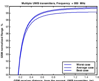
Let us study the case of multiple UWB transmitters affecting the GSM-900 system. Fig. 5 shows the GSM
normalized downlink range Rn as a function of the
distance between the GSM-900 mobile and the nearest UWB transmitter, when the UWB power density is -93.5 dBm/MHz. It can be noticed that for the worst
case, Rn has a value of 99% which produces an
acceptable macrocell range reduction (1%).
Let us study the case of multiple UWB transmitters affecting the GSM-900 system, assuming that the outdoor propagation exponent for the GSM macrocell is 4. Fig. 6 shows the GSM normalized downlink range Rn as a function of the distance between the GSM-900 mobile and the nearest UWB transmitter when the UWB power density is -93.0 dBm/MHz. It can be noticed that for the worst case, Rn has a value of 99% which produces an acceptable macrocell range reduction (1%).
0 0.2 0.4 0.6 0.8 1 1.2 1.4 1.6 90
91 92 93 94 95 96 97 98 99 100
GSM receiver distance from the nearest UWB transmitter (m)
G
S
M
norm
a
li
z
e
d
R
a
nge
%
Multiple UWB transmitters, Frequency = 950 MHz
Worst case Average case Best case
Fig. 5: GSM-900 normalized macrocell range as a function of distances between the GSM-900 mobile receiver and the nearest UWB transmitter for (PUWB = -93.5 dBm/MHz and 16 UWB transmitters).
B
0 0.2 0.4 0.6 0.8 1 1.2 1.4 1.6 90
91 92 93 94 95 96 97 98 99 100
GSM receiver distance from the nearest UWB transmitter (m)
G
S
M
n
o
rm
al
iz
ed
R
an
g
e
%
Multiple UWB transmitters, Frequency = 950 MHz
Worst case Average case Best case
Fig. 6: GSM-900 normalized macrocell range as a
function of distances between the GSM-900 mobile receiver and the nearest UWB transmitter for (PUWB = -93 dBm/MHz, 16 UWB transmitters and α = 4.0).
B
Thus, form the results of Figs. 5 and 6, it can be noticed that the effect of the outdoor propagation exponent is very small (The recommended UWB power
density when α = 4 is only 0.5 dB higher than the
recommended UWB power density when α = 3.5).
Finally, we study the case of GSM-900 microcells assuming that α is equal to α2 which is the second propagation exponent valid after the break point in the two-slope propagation loss model. The propagation exponent α2 has a typical value betwenn 4 and 5. Fig. 7
shows the GSM microcell normalized downlink range Rn as a function of the distance between the GSM-900 mobile and the nearest UWB transmitter, when the UWB power density is -92.5 dBm/MHz and α2 = 4.5. It can be noticed that for the worst case, Rn has a value of 99% which produces an acceptable macrocell range reduction (1%). Thus, it can be concluded that, the recommended UWB power density for microcells is 1 dB higher than the recommended UWB power density for macrocells.
If the critical distance is reduced from 1.0 to 0.5 m, then the recommended power density of the UWB system should be 6 dB lower than the previously given values.
0 0.2 0.4 0.6 0.8 1 1.2 1.4 1.6 95
95.5 96 96.5 97 97.5 98 98.5 99 99.5 100
GSM receiver distance from the nearest UWB transmitter (m)
G
S
M
m
ic
ro
c
el
l n
o
rm
al
iz
ed
R
an
g
e
%
Multiple UWB transmitters, Frequency = 950 MHz
Worst case Average case Best case
Fig. 7: GSM-900 microcell normalized range as a function of distances between the GSM-900 mobile receiver and the nearest UWB transmitter for (PUWB =
-92.5 dBm/MHz, 16 UWB transmitters and α
B
2= 4.5).
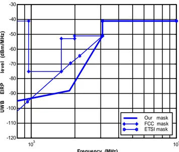
Fig. 8 shows the FCC, ETSI and our recommended radiation mask for indoor applications, resulting from this work. For a frequency greater than or equal to 3.1 GHz, the three masks have the same values of the UWB accepted power density.
103 104 -120
-110 -100 -90 -80 -70 -60 -50 -40 -30
Frequency (MHz)
U
W
B
E
IR
P
le
v
e
l (
d
B
m
/M
H
z
)
Our mask FCC mask ETSI mask
Fig. 8: The FCC, ETSI and our recommended radiation masks.
4- Conclusions
We have studied the effect of the UWB transmitters on the DCS-1800 and GSM-900 downlink for different UWB power density values. For high UWB power density (-60 dBm/MHz), the effect of the UWB signals is very high when the distance between the UWB transmitter and the DCS-1800 receiver is less than 1 m. Also the same conclusion is valid for the GSM-900 system. For low UWB power density (-90.5 dBm/MHz) or less, the effect of the UWB signals is very low even when the distance between the UWB transmitter and the DCS-1800 receiver is less than 1 m. For low UWB power density (-97 dBm/MHz or less), the effect of the UWB signals is very low even when the distance between the UWB transmitter and the GSM-900 receiver is lower than 1 m.
REFERENCES
[1] M. Hamalainen, V. Hovinrn, R. Tesi, J. Iinatti, and M. Latava-aho, “ On the UWB System Coexistance with GSM900, UMTS/WCDMA, and GPS”, IEEE Journal on Selected Areas in Communications, Vol. 20, No. 9, pp. 1712-1721, Dec. 2002.
[2] M. Hamalinen, R. Tesi., J. Iinatti, ” UWB
co-existence with IEEE802.11a and UMTS in
modified Saleh-Valenzuela channel”, Ultra
Wideband Systems, 2004. Joint with Conference on Ultrawideband Systems and Technologies. 2004 International Workshop on Joint UWBST & IWUWBS., pp:45 – 49, May 18-21, 2004.
[3] R. Giuliano, , F. Mazzenga, ,F. Vatalaro, “On the interference between UMTS and UWB systems”, pp: 339 – 343, Ultra Wideband Systems and Technologies, 2003 IEEE Conference on , 16-19 Nov. 2003.
[4] M. Hamalinen, V. Hovinen, J. Iinatti, M.
Latva-aho: "In-band Interference Power Caused by Different Kinds of UWB Signals at UMTS/WCDMA Frequency Bands", , the 2001 IEEE Radio and Wireless Conference, RAWCON 2001, pp. 97-100,Waltham-Boston, Massachusetts, USA, Aug. , 2001.
[5] M. Hamalinen, J. Iinatti, V. Hovinen, M.
Latva-aho:" In-band Interference of Three Kind of UWB Signals in GPS L1 Band and GSM900 Uplink
Band", the 12th International Symposium on
Personal, Indoor and Mobile Radio Communications, PIMRC2001, pp. D 76-80, USA, Sep - Oct , 2001.
[6] B. Taha-Ahmed, M. Calvo-Ramon, and L.
Haro-Ariet, “Impact of Ultra Band (UWB) on Macrocell Downlink of DCS-1800 and GSM-900 Systems”, Radioenginnering, Vol. 14, No.1, pp. 51-55, April 2005.
[7] W. Ciccoganini, A. Durantini, and D. Cassioli,