EVALUACION FINAL
PRUEBA DE HABILIDADES PRACTICAS CISCO CCNP
MIGUEL ANGEL IBARGUEN GIRALDO
UNIVERSIDAD NACIONAL ABIERTA Y A DISTANCIA INGENIERIA ELECTRÓNICA
DIPLOMADO CISCO CCNP BOGOTÁ
EVALUACION PRUEBA DE HABILIDADES PRACTICAS CCNP
MIGUEL ANGEL IBARGUEN GIRALDO
Diplomado de profundización cisco CCNP prueba de Habilidades prácticas
Gerardo Granados Acuña Magíster en Telemática
UNIVERSIDAD NACIONAL ABIERTA Y A DISTANCIA INGENIERIA ELECTRÓNICA
DIPLOMADO CISCO CCNP BOGOTÁ
NOTA DE ACEPTACION
______________________________ ______________________________ ______________________________ ______________________________ ______________________________ ______________________________ ______________________________
______________________________ Presidente del jurado
______________________________ Jurado
______________________________ Jurado
4
TABLA DE CONTENIDO
Pág.
INTRODUCCIÓN ... 10
1. DESARROLLO DE ESCENARIOS ... 11
1.1 Escenario 1 ... 11
2.1 Escenario 2 ... 22
3.1 Escenario 3 ... 36
2. CONCLUSIONES ... 56
5
LISTA DE TABLAS
Pág.
Tabla 1. Direccionamiento IP Escenario 2 ... 22
Tabla 2. Asociación de puertos a VLAN ... 47
6
LISTA DE FIGURAS
Pág.
Figura 1. Escenario 1 ... 11
Figura 2. Analisis comando show ip route en R3 ... 18
Figura 3. Verificación de enrutamiento en R1 ... 20
Figura 4. Verificación de enrutamiento en R5 ... 21
Figura 5. Escenario 2 ... 22
Figura 6. Comando show ip route en R1 ... 28
Figura 7. Comando show ip route en R2 ... 29
Figura 8. Comando show ip route en R2 ... 30
Figura 9. Comando show ip route en R3 ... 31
Figura 10. Comando show ip route en R4 ... 33
Figura 11. Comando show ip route en R3 ... 34
Figura 12. Comando show ip route en R1 ... 35
Figura 13. Escenario 3 ... 36
Figura 14. Comando show vtp status en SWT2 ... 39
Figura 15. Comando show vtp status en SWT1 ... 40
Figura 16. Comando show vtp status en SWT3 ... 41
Figura 17. Comando show interface trunk SWT2 ... 42
Figura 18. Comando show interface trunk SWT1 ... 43
Figura 19. Comando show interface trunk SWT1 ... 44
7
Figura 21. Comando show vlan en SWT2 ... 46
Figura 22. Comando show vlan en SWT3 ... 47
Figura 23. Verificación de ping desde PC1 ... 53
Figura 24. Verificación de ping desde SWT1 ... 54
8 GLOSARIO
CCNP: (Cisco Certified Network Professional) es un curso de profundización en redes de Cisco que pretende desarrollar todas las habilidades en el diseño de redes y solución de problemas en los módulos Switching y Routing.
Packet Tracer: Simulador de red diseñado por Cisco que permite desarrollar
arquitecturas de red empresariales complejas mejorando el tiempo de desarrollo y la solución de problemas sin estar limitados a entornos y equipos físicos.
Switching: El termino switching se enfoca en los dispositivo Switch y como este
toma la información y la reenvía a través de sus puertos de comunicación utilizando una serie de protocolos como VLAN, VTP, RSTP y PVSTP para optimizar y mejorar el flujo de datos de las redes LAN.
Routing: El termino Routing se enfoca en los dispositivo Router y su función principal es la de encaminar paquetes a través de las redes incluso estando estas redes en diferentes países comúnmente denomina como redes WAN y para realizar el envió de esta información los Router utilizan los siguientes protocolos de enrutamiento dinámico OSPF, RIP y EIGRP.
9 RESUMEN
Este trabajo busca evaluar el desempeño obtenido en el curso de profundización de cisco CCNP con la solución de tres escenarios propuestos donde se deberá evidenciar la utilización de los protocolos de Switching y Routing aprendidos durante el curso.
El primer escenario abordara los protocolos de enrutamiento OSPF y EIGRP asociados a Routing y se deberá enlazar las redes pertenecientes al área 0 de OSPF y al sistema autónomo AS 0 de EIGRP.
El segundo escenario se deberá configurar los router utilizando el protocolo de enrutamiento EBGP y mediante pantallazos evidenciar el correcto funcionamiento.
Por último el tercer escenario se enfocara en los protocolos de Switching y en la creación de VLAN y enlaces troncales entre los dispositivos propuestos en la arquitectura de red.
10
INTRODUCCIÓN
Este trabajo evaluara el desempeño del estudiante durante el curso y las habilidades adquiridas en la configuración de dispositivos capa dos y capa tres como lo son los Switch y Router en los módulos de CCNP SWITCH y CCNP ROUTE del curso de profundización de cisco, para esto se proponen tres escenarios en el que se deben configurar los protocolos de enrutamiento OSPF, EIGRP, EBGP y el protocolo de administración de VLANs VTP.
11
1. DESARROLLO DE ESCENARIOS
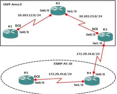
1.1 Escenario 1
Figura 1. Escenario 1
1. Aplique las configuraciones iniciales y los protocolos de enrutamiento para los routers R1, R2, R3, R4 y R5 según el diagrama. No asigne passwords en los routers. Configurar las interfaces con las direcciones que se muestran en la topología de red.
Configuración Inicial en los Router
Router>enable
Router#configure terminal
Enter configuration commands, one per line. End with CNTL/Z. Router(config)#hostname R1
R1(config)#no ip domain-lookup R1(config)#line con 0
12 Router>enable
Router#configure terminal
Enter configuration commands, one per line. End with CNTL/Z. Router(config)#hostname R2
R2(config)#no ip domain-lookup R2(config)#line con 0
R2(config-line)#logging syn R2(config-line)#exec-timeout 0 0 R2(config-line)#exit
R2(config)# Router>
Router>enable
Router#configure terminal
Enter configuration commands, one per line. End with CNTL/Z. Router(config)#hostname R3
R3(config)#no ip domain-lookup R3(config)#line con 0
R3(config-line)#logging syn R3(config-line)#exec-timeout 0 0 R3(config-line)#exit
R3(config)# Router>enable
Router#configure terminal
Enter configuration commands, one per line. End with CNTL/Z. Router(config)#no ip domain-lookup
Router(config)#line con 0 Router(config-line)#logging syn Router(config-line)#exec-timeout 0 0 Router(config-line)#exit
Router(config)#hostname R4 R4(config)#
Router>enable
Router#configure terminal
Enter configuration commands, one per line. End with CNTL/Z. Router(config)#hostname R5
R5(config)#no ip domain-lookup R5(config)#line con 0
R5(config-line)#exec-timeout 0 0 R5(config-line)#exit
13
Configuración de direcciones en R1 según topología
R1(config)#interface s0/0/0
R1(config-if)#ip address 10.103.12.1 255.255.255.0 R1(config-if)#clock rate 128000
Unknown clock rate
R1(config-if)#no shutdown
Configuración de direcciones en R2 según topología
R2(config)#interface s0/0/0
R2(config-if)#ip address 10.103.12.2 255.255.255.0 R2(config-if)#no shutdown
R2(config)#interface s0/0/1
R2(config-if)#ip address 10.103.23.1 255.255.255.0 R2(config-if)#no shutdown
R3(config)#interface s0/0/0
R3(config-if)#ip address 10.103.23.2 255.255.255.0 R3(config-if)#clock rate 128000
R3(config-if)#no shutdown
Configuración de direcciones en R3 según topología
R3(config)#interface s0/0/1
R3(config-if)#ip address 172.29.34.1 255.255.255.0 R3(config-if)#no shutdown
Configuración de direcciones en R4 según topología R4(config)#interface s0/0/0
R4(config-if)#ip address 172.29.34.2 255.255.255.0 R4(config-if)#no shutdown
R4(config-if)#exit
R4(config)#interface s0/0/1
R4(config-if)#ip address 172.29.45.1 255.255.255.0 R4(config-if)#no shutdown
Configuración de direcciones en R5 según topología
R5(config)#interface s0/0/0
14 R5(config-if)#no shutdown
Configuración de Protocolos de enrutamientos en R1 R1(config)#router ospf 1
R1(config-router)#router-id 1.1.1.1
R1(config-router)#network 10.103.12.0 0.0.0.255 area 0 R1(config-router)#
Configuración de Protocolos de enrutamientos en R2 R2(config)#router ospf 1
R2(config-router)#router-id 2.2.2.2
R2(config-router)#network 10.103.12.0 0.0.0.255 area 0 R2(config-router)#network
00:52:50: %OSPF-5-ADJCHG: Process 1, Nbr 1.1.1.1 on Serial0/0/0 from LOADING to FULL, Loading Done
R2(config-router)#network 10.103.23.0 0.0.0.255 area 0 R2(config-router)#
Configuración de Protocolos de enrutamientos en R3 R3(config)#router ospf 1
R3(config-router)#router-id 3.3.3.3
R3(config-router)#network 10.103.23.0 0.0.0.255 area 0 R3(config-router)#
00:55:00: %OSPF-5-ADJCHG: Process 1, Nbr 2.2.2.2 on Serial0/0/0 from LOADING to FULL, Loading Done
R3(config)#router eigrp 10
R3(config-router)#network 172.29.34.0 0.0.0.255 R3(config-router)#
Configuración de Protocolos de enrutamientos en R4
R4(config)#router eigrp 10
15
R4(config-router)#network 172.29.34.0 0.0.0.255 R4(config-router)#
Configuración de Protocolos de enrutamientos en R5 R5(config)#router eigrp 10
R5(config-router)#network 172.29.45.0 0.0.0.255 R5(config-router)#
%DUAL-5-NBRCHANGE: IP-EIGRP 10: Neighbor 172.29.45.1 (Serial0/0/0) is up: new adjacency
2. Cree cuatro nuevas interfaces de Loopback en R1 utilizando la
asignación de direcciones 10.1.0.0/22 y configure esas interfaces para participar en el área 0 de OSPF.
Creación de loopback1
R1#configure terminal
Enter configuration commands, one per line. End with CNTL/Z. R1(config)#interface loopback1
R1(config-if)#
%LINK-5-CHANGED: Interface Loopback1, changed state to up
%LINEPROTO-5-UPDOWN: Line protocol on Interface Loopback1, changed state to up
R1(config-if)#ip address 10.1.1.1 255.255.252.0 R1(config-if)#exit
Creación de la loopback2
R1(config)#interface loopback2 R1(config-if)#
%LINK-5-CHANGED: Interface Loopback2, changed state to up
%LINEPROTO-5-UPDOWN: Line protocol on Interface Loopback2, changed state to up
R1(config-if)#ip address 10.1.2.1 255.255.255.0 % 10.1.2.0 overlaps with Loopback1
16 R1(config-if)#exit
Creación de la loopback3
R1(config)#interface loopback3 R1(config-if)#
%LINK-5-CHANGED: Interface Loopback3, changed state to up
%LINEPROTO-5-UPDOWN: Line protocol on Interface Loopback3, changed state to up
R1(config-if)#ip address 10.1.9.1 255.255.252.0 R1(config-if)#exit
Creación de la loopback4
R1(config)#interface loopback4 R1(config-if)#
%LINK-5-CHANGED: Interface Loopback4, changed state to up
%LINEPROTO-5-UPDOWN: Line protocol on Interface Loopback4, changed state to up
R1(config-if)#ip address 10.1.13.1 255.255.252.0 R1(config-if)#exit
R1(config)#
Configuración de la participación de las interfaces loopback en el área 0 de ospf
R1(config)#router ospf 1
R1(config-router)#router-id 1.1.1.1
R1(config-router)#network 10.1.0.0 0.0.3.255 % Incomplete command.
R1(config-router)#network 10.1.0.0 0.0.3.255 area 0 R1(config-router)#
17 Creación de la loopback5
R5(config-router)#exit
R5(config)#interface loopback5
R5(config-if)#
%LINK-5-CHANGED: Interface Loopback5, changed state to up
%LINEPROTO-5-UPDOWN: Line protocol on Interface Loopback5, changed state to up
R5(config-if)#ip address 172.5.1.1 255.255.252.0 R5(config-if)#exit
Creación de la loopback6
R5(config)#interface loopback6 R5(config-if)#
%LINK-5-CHANGED: Interface Loopback6, changed state to up
%LINEPROTO-5-UPDOWN: Line protocol on Interface Loopback6, changed state to up
R5(config-if)#ip address 172.5.5.1 255.255.252.0 R5(config-if)#exit
Creación de la loopback7
R5(config)#interface loopback7 R5(config-if)#
%LINK-5-CHANGED: Interface Loopback7, changed state to up
%LINEPROTO-5-UPDOWN: Line protocol on Interface Loopback7, changed state to up
R5(config-if)#ip address 172.5.9.1 255.255.252.0 R5(config-if)#exit
Creación de la loopback8
R5(config)#interface loopback8 R5(config-if)#
%LINK-5-CHANGED: Interface Loopback8, changed state to up
%LINEPROTO-5-UPDOWN: Line protocol on Interface Loopback8, changed state to up
18 R5(config)#
Configuración de la participación de las interfaces loopback en el AS 10 de EIGRP
R5(config)#route eigrp 10
R5(config-router)#auto-summary R5(config-router)#
%DUAL-5-NBRCHANGE: IP-EIGRP 10: Neighbor 172.29.45.1 (Serial0/0/0) resync: summary configured
R5(config-router)#network 172.5.0.0 0.0.3.255 R5(config-router)#exit
R5(config)#
4. Analice la tabla de enrutamiento de R3 y verifique que R3 está aprendiendo las nuevas interfaces de Loopback mediante el comando show ip route.
19
5. Configure R3 para redistribuir las rutas EIGRP en OSPF usando el costo de 50000 y luego redistribuya las rutas OSPF en EIGRP usando un ancho de banda T1 y 20,000 microsegundos de retardo.
Configuración y redistribución de ospf en eigrp
R3(config)#router ospf 1
R3(config-router)#network 172.29.34.0 0.0.0.255 area 0 R3(config-router)#redistribute eigrp 10 subnets
R3(config-router)#log-adjacency-changes
R3(config-router)#network 172.29.45.0 0.0.0.255 area 0
Configuración y redistribución de eigrp en ospf R3(config-router)#router eigrp 10
R3(config-router)#redistribute ospf 1 metric 50000 200 255 1 1500 R3(config-router)#auto-summary
R3(config-router)#exit
20
21
22 2.1 Escenario 2
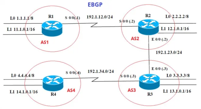
Figura 5. Escenario 2
Tabla 1. Direccionamiento IP Escenario 2
R1 Interfaz Dirección IP Máscara
Loopback 0 1.1.1.1 255.0.0.0
Loopback 1 11.1.0.1 255.255.0.0
S 0/0 192.1.12.1 255.255.255.0
R2 Interfaz Dirección IP Máscara
Loopback 0 2.2.2.2 255.0.0.0
Loopback 1 12.1.0.1 255.255.0.0
S 0/0 192.1.12.2 255.255.255.0
23
R3 Interfaz Dirección IP Máscara
Loopback 0 3.3.3.3 255.0.0.0
Loopback 1 13.1.0.1 255.255.0.0
E 0/0 192.1.23.3 255.255.255.0
S 0/0 192.1.34.3 255.255.255.0
R4 Interfaz Dirección IP Máscara
Loopback 0 4.4.4.4 255.0.0.0
Loopback 1 14.1.0.1 255.255.0.0
S 0/0 192.1.34.4 255.255.255.0
1. Configure una relación de vecino BGP entre R1 y R2. R1 debe estar en AS1 y R2 debe estar en AS2. Anuncie las direcciones de Loopback en BGP. Codifique los ID para los routers BGP como 11.11.11.11 para R1 y como 22.22.22.22 para R2. Presente el paso a con los comandos utilizados y la salida del comando show ip route.
Configuración Inicial en los Router Router>enable
Router#configure terminal
Enter configuration commands, one per line. End with CNTL/Z. Router(config)#hostname R1_AS1
R1_AS1(config)#no ip domain-lookup R1_AS1(config)#line con 0
R1_AS1(config-line)#logging syn R1_AS1(config-line)#exec-timeout 0 0 R1_AS1(config-line)#exit
R1_AS1(config)#
Router>enable
Router#configure terminal
Enter configuration commands, one per line. End with CNTL/Z. Router(config)#hostname R2_AS2
R2_AS2(config)#no ip domain-lookup R2_AS2(config)#line con 0
24 R2_AS2(config-line)#exit
R2_AS2(config)#
Router>enable
Router#configure terminal
Enter configuration commands, one per line. End with CNTL/Z. Router(config)#hostname R3_AS3
R3_AS3(config)#no ip domain-lookup R3_AS3(config)#line con 0
R3_AS3(config-line)#logging syn R3_AS3(config-line)#exec-timeout 0 0 R3_AS3(config-line)#exit
R3_AS3(config)#
Router>enable
Router#configure terminal
Enter configuration commands, one per line. End with CNTL/Z. Router(config)#hostname R4_AS4
R4_AS4(config)#no ip domain-lookup R4_AS4(config)#line con 0
R4_AS4(config-line)#logging syn R4_AS4(config-line)#exec-timeout 0 0 R4_AS4(config-line)#exit
R4_AS4(config)#
Creación de loopback y asignación de direcciones IP según tabla de configuración en R1
R1_AS1(config)#interface loopback0 R1_AS1(config-if)#
%LINK-5-CHANGED: Interface Loopback0, changed state to up
%LINEPROTO-5-UPDOWN: Line protocol on Interface Loopback0, changed state to up
R1_AS1(config-if)#ip address 1.1.1.1 255.0.0.0 R1_AS1(config-if)#exit
R1_AS1(config)#interface loopback1 R1_AS1(config-if)#
%LINK-5-CHANGED: Interface Loopback1, changed state to up
%LINEPROTO-5-UPDOWN: Line protocol on Interface Loopback1, changed state to up
25 R1_AS1(config-if)#exit
R1_AS1(config)#interface s0/0/0
R1_AS1(config-if)#ip address 192.1.12.1 255.255.255.0 R1_AS1(config-if)#no shutdown
%LINK-5-CHANGED: Interface Serial0/0/0, changed state to down R1_AS1(config-if)#
Creación de loopback y asignación de direcciones IP según tabla de configuración en R2
R2_AS2(config)#interface loopback0 R2_AS2(config-if)#
%LINK-5-CHANGED: Interface Loopback0, changed state to up
%LINEPROTO-5-UPDOWN: Line protocol on Interface Loopback0, changed state to up
R2_AS2(config-if)#ip address 2.2.2.2 255.0.0.0 R2_AS2(config-if)#exit
R2_AS2(config)#interface loopback1 R2_AS2(config-if)#
%LINK-5-CHANGED: Interface Loopback1, changed state to up
%LINEPROTO-5-UPDOWN: Line protocol on Interface Loopback1, changed state to up
R2_AS2(config-if)#ip address 12.1.0.1 255.255.0.0 R2_AS2(config-if)#exit
R2_AS2(config)#interface s0/0/0
R2_AS2(config-if)#ip address 192.1.12.2 255.255.255.0 R2_AS2(config-if)#no shutdown
R2_AS2(config-if)#
%LINK-5-CHANGED: Interface Serial0/0/0, changed state to up R2_AS2(config-if)#
%LINEPROTO-5-UPDOWN: Line protocol on Interface Serial0/0/0, changed state to up
R2_AS2(config-if)#exit
R2_AS2(config)#interface g0/0
R2_AS2(config-if)#ip address 192.1.23.2 255.255.255.0 R2_AS2(config-if)#no shutdown
R2_AS2(config-if)#
%LINK-5-CHANGED: Interface GigabitEthernet0/0, changed state to up R2_AS2(config-if)#exit
R2_AS2(config)# R2_AS2#
26
Creación de loopback y asignación de direcciones IP según tabla de configuración en R3
R3_AS3(config)#interface loopback0 R3_AS3(config-if)#
%LINK-5-CHANGED: Interface Loopback0, changed state to up
%LINEPROTO-5-UPDOWN: Line protocol on Interface Loopback0, changed state to up
R3_AS3(config-if)#ip address 3.3.3.3 255.0.0.0 R3_AS3(config-if)#exit
R3_AS3(config)#interface lookback1 ^
% Invalid input detected at '^' marker. R3_AS3(config)#interface loopback1 R3_AS3(config-if)#
%LINK-5-CHANGED: Interface Loopback1, changed state to up
%LINEPROTO-5-UPDOWN: Line protocol on Interface Loopback1, changed state to up
R3_AS3(config-if)#ip address 13.1.0.1 255.255.0.0 R3_AS3(config-if)#exit
R3_AS3(config)#interface g0/0
R3_AS3(config-if)#ip address 192.1.23.3 255.255.255.0 R3_AS3(config-if)#no shutdwon
^
% Invalid input detected at '^' marker. R3_AS3(config-if)#no shutdown R3_AS3(config-if)#
%LINK-5-CHANGED: Interface GigabitEthernet0/0, changed state to up %LINEPROTO-5-UPDOWN: Line protocol on Interface GigabitEthernet0/0, changed state to up
R3_AS3(config-if)#exit
R3_AS3(config)#interface s0/0/0
R3_AS3(config-if)#ip address 192.1.34.3 255.255.255.0 R3_AS3(config-if)#no shutdown
%LINK-5-CHANGED: Interface Serial0/0/0, changed state to down R3_AS3(config-if)#
Creación de loopback y asignación de direcciones IP según tabla de configuración en R4
R4_AS4(config)#interface loopback0 R4_AS4(config-if)#
27
%LINEPROTO-5-UPDOWN: Line protocol on Interface Loopback0, changed state to up
R4_AS4(config-if)#ip address 4.4.4.4 255.0.0.0 R4_AS4(config-if)#exit
R4_AS4(config)#interface loopback1 R4_AS4(config-if)#
%LINK-5-CHANGED: Interface Loopback1, changed state to up
%LINEPROTO-5-UPDOWN: Line protocol on Interface Loopback1, changed state to up
R4_AS4(config-if)#ip address 14.1.0.1 255.255.0.0 R4_AS4(config-if)#exit
R4_AS4(config)#interface s0/0/0
R4_AS4(config-if)#ip address 192.1.34.4 255.255.255.0 R4_AS4(config-if)#no shutdown
R4_AS4(config-if)#
%LINK-5-CHANGED: Interface Serial0/0/0, changed state to up R4_AS4(config-if)#
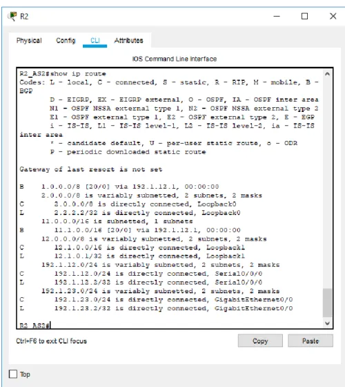
2. Configure una relación de vecino BGP entre R1 y R2. R1 debe estar en AS1 y R2 debe estar en AS2. Anuncie las direcciones de Loopback en BGP. Codifique los ID para los routers BGP como 11.11.11.11 para R1 y como 22.22.22.22 para R2. Presente el paso a con los comandos utilizados y la salida del comando show ip route.
Configuración de BGP en R1 R1_AS1(config-if)#exit
R1_AS1(config)#router bgp 1
R1_AS1(config-router)#bgp router-id 11.11.11.11
R1_AS1(config-router)#neighbor 192.1.12.2 remote-as 2 R1_AS1(config-router)#network 1.1.1.1 mask 255.0.0.0 R1_AS1(config-router)#network 11.1.0.1 mask 255.255.0.0 R1_AS1(config-router)#exit
R1_AS1(config)#end R1_AS1#
Configuración de BGP en R2 R2_AS2#configure terminal
28
R2_AS2(config-router)#bgp router-id 22.22.22.22
R2_AS2(config-router)#neighbor 192.1.12.1 remote-as 1
R2_AS2(config-router)#%BGP-5-ADJCHANGE: neighbor 192.1.12.1 Up
R2_AS2(config-router)#network 2.2.2.2 mask 255.0.0.0 R2_AS2(config-router)#network 12.1.0.1 mask 255.255.0.0 R2_AS2(config-router)#exit
R2_AS2(config)#
29
Figura 7. Comando show ip route en R2
3. Configure una relación de vecino BGP entre R2 y R3. R2 ya debería estar configurado en AS2 y R3 debería estar en AS3. Anuncie las direcciones de Loopback de R3 en BGP. Codifique el ID del router R3 como 33.33.33.33. Presente el paso a con los comandos utilizados y la salida del comando show ip route.
Configuración de BGP en R2
R2_AS2#configure terminal
30 R2_AS2(config)#router bgp 2
R2_AS2(config-router)#neighbor 192.1.23.3 remote-as 3 R2_AS2(config-router)#
R3_AS3(config-if)#exit
Configuración de BGP en R3 R3_AS3(config)#router bgp 3
R3_AS3(config-router)#bgp router-id 33.33.33.33
R3_AS3(config-router)#neighbor 192.1.23.2 remote-as 2
R3_AS3(config-router)#%BGP-5-ADJCHANGE: neighbor 192.1.23.2 Up R3_AS3(config-router)#network 3.3.3.3 mask 255.0.0.0
R3_AS3(config-router)#network 13.1.0.1 mask 255.255.0.0 R3_AS3(config-router)#
31
Figura 9. Comando show ip route en R3
32 Configuración de BGP en R3
R3_AS3#configure terminal
Enter configuration commands, one per line. End with CNTL/Z. R3_AS3(config)#router bgp 3
R3_AS3(config-router)#neighbor 192.1.34.4 remote-as 4 R3_AS3(config-router)#
Configuración de BGP en R3 R4_AS4(config-if)#exit
R4_AS4(config)#router bgp 4
R4_AS4(config-router)#network 4.4.4.4 mask 255.0.0.0 R4_AS4(config-router)#network 14.1.0.1 mask 255.255.0.0 R4_AS4(config-router)#bgp router-id 44.44.44.44
R4_AS4(config-router)#neigbor 3.3.3.3 remote-as 3 ^
% Invalid input detected at '^' marker.
R4_AS4(config-router)#neighbor 3.3.3.3 remote-as 3 R4_AS4(config-router)#neighbor 2.2.2.2 remote-as 2 R4_AS4(config-router)#neighbor 1.1.1.1 remote-as 1 R4_AS4(config-router)#neighbor 192.1.34.3 remote-as 3
R4_AS4(config-router)#%BGP-5-ADJCHANGE: neighbor 192.1.34.3 Up
R4_AS4(config-router)#%BGP-5-ADJCHANGE: neighbor 3.3.3.3 Up
R4_AS4(config-router)#%BGP-5-ADJCHANGE: neighbor 192.1.34.3 Up
R4_AS4(config-router)#exit
R4_AS4(config)#access-list 1 permit 14.1.0.0 0.0.255.255 R4_AS4(config)#end
33
34
35
36 3.1 Escenario 3
Figura 13. Escenario 3
A. Configurar VTP
1. Todos los switches se configurarán para usar VTP para las actualizaciones de VLAN. El switch SWT2 se configurará como el servidor. Los switches SWT1 y SWT3 se configurarán como clientes. Los switches estarán en el dominio VPT llamado CCNP y usando la contraseña cisco.
Configuración inicial Switches Switch>enable
Switch#configure terminal
Enter configuration commands, one per line. End with CNTL/Z. Switch(config)#hostname SWT1
37 SWT1(config)#line con 0
SWT1(config-line)#logging syn SWT1(config-line)#exec-timeout 0 0 SWT1(config-line)#exit
Switch>enable
Switch#configure terminal
Enter configuration commands, one per line. End with CNTL/Z. Switch(config)#hostname SWT2
SWT2(config)#no ip domain-lookup SWT2(config)#line con 0
SWT2(config-line)#logging syn SWT2(config-line)#exec-timeout 0 0 SWT2(config-line)#exit SWT2(config)# SWT2# Switch>enable Switch#configure termnial ^
% Invalid input detected at '^' marker. Switch#configure terminal
Enter configuration commands, one per line. End with CNTL/Z. Switch(config)#hostname SWT3
SWT3(config)#no ip domain-lookup SWT3(config)#line con 0
SWT3(config-line)#logging syn SWT3(config-line)#exec-timeout 0 0 SWT3(config-line)#exit
SWT3(config)#
Configuración VTP SWT2 como server
SWT2#configure terminal
Enter configuration commands, one per line. End with CNTL/Z. SWT2(config)#vtp domain CCNP
Changing VTP domain name from NULL to CCNP SWT2(config)#vtp version 2
SWT2(config)#vtp mode server Device mode already VTP SERVER. SWT2(config)#vtp password cisco
38 Configuración VTP SWT1 como cliente
SWT1#configure terminal
Enter configuration commands, one per line. End with CNTL/Z. SWT1(config)#vtp mode client
Setting device to VTP CLIENT mode. SWT1(config)#vtp domain CCNP
Changing VTP domain name from NULL to CCNP SWT1(config)#vtp password cisco
Setting device VLAN database password to cisco SWT1(config)#end
SWT1#
Configuración VTP SWT3 como cliente SWT3(config)#vtp mode client
Setting device to VTP CLIENT mode. SWT3(config)#vtp domain CCNP
Changing VTP domain name from NULL to CCNP SWT3(config)#vtp password cisco
Setting device VLAN database password to cisco SWT3(config)#end
39
40
41
Figura 16. Comando show vtp status en SWT3
B. Configurar DTP (Dynamic Trunking Protocol)
1. Configure un enlace troncal ("trunk") dinámico entre SWT1 y SWT2. Debido a que el modo por defecto es dynamic auto, solo un lado del enlace debe configurarse como dynamic desirable.
Configurando enlace troncal del SWT2 como dynamic desirable
SWT2#configure terminal
Enter configuration commands, one per line. End with CNTL/Z. SWT2(config)#interface fa0/1
SWT2(config-if)#switchport mode dynamic desirable SWT2(config-if)#
42
%LINEPROTO-5-UPDOWN: Line protocol on Interface FastEthernet0/1, changed state to down
%LINEPROTO-5-UPDOWN: Line protocol on Interface FastEthernet0/1, changed state to up
SWT2(config-if)#
2. Verifique el enlace "trunk" entre SWT1 y SWT2 usando el comando show interfaces trunk.
43
Figura 18. Comando show interface trunk SWT1
3. Entre SWT1 y SWT3 configure un enlace "trunk" estático utilizando el comando switchport mode trunk en la interfaz F0/3 de SWT1
SWT1#configure terminal
Enter configuration commands, one per line. End with CNTL/Z. SWT1(config)#interfaces fa0/3
^
% Invalid input detected at '^' marker. SWT1(config)#interface fa0/3
SWT1(config-if)#switchport mode trunk SWT1(config-if)#
%LINEPROTO-5-UPDOWN: Line protocol on Interface FastEthernet0/3, changed state to down
%LINEPROTO-5-UPDOWN: Line protocol on Interface FastEthernet0/3, changed state to up
44
4. Verifique el enlace "trunk" el comando show interfaces trunk en SWT1.
Figura 19. Comando show interface trunk SWT1
5. Configure un enlace "trunk" permanente entre SWT2 y SWT3.
SWT2#configure terminal
Enter configuration commands, one per line. End with CNTL/Z. SWT2(config)#interface fa0/3
SWT2(config-if)#switchport mode trunk
SWT2(config-if)#
%LINEPROTO-5-UPDOWN: Line protocol on Interface FastEthernet0/3, changed state to down
%LINEPROTO-5-UPDOWN: Line protocol on Interface FastEthernet0/3, changed state to up
45 SWT3#configure terminal
Enter configuration commands, one per line. End with CNTL/Z. SWT3(config)#interface fa0/1
SWT3(config-if)#switchport mode trunk SWT3(config-if)#
C. Agregar VLANs y asignar puertos.
1. En STW1 agregue la VLAN 10. En STW2 agregue las VLANS Compras (10), Mercadeo (20), Planta (30) y Admon (99)
Se intenta configurar Vlan 10 en SWT1, pero rechaza el comando por estar configurado en modo cliente del VTP
SWT1#configure terminal
Enter configuration commands, one per line. End with CNTL/Z. SWT1(config)#vlan 10
VTP VLAN configuration not allowed when device is in CLIENT mode. SWT1(config)#
Creación de VLAN en SWT2
SWT2(config-if)#exit SWT2(config)#vlan 10 SWT2(config-vlan)#name COMPRAS SWT2(config-vlan)#vlan 20 SWT2(config-vlan)#name MERCADEO SWT2(config-vlan)#vlan 30 SWT2(config-vlan)#name PLANTA SWT2(config-vlan)#vlan 99 SWT2(config-vlan)#name ADMON SWT2(config-vlan)#end SWT2#
46
Figura 20. Comando show vlan en SWT1
47
Figura 22. Comando show vlan en SWT3
3. Asocie los puertos a las VLAN y configure las direcciones IP de acuerdo con la siguiente tabla.
Tabla 2. Asociación de puertos a VLAN
Interfaz VLAN Direcciones IP de los PCs
F0/10 VLAN 10 190.108.10.X / 24 F0/15 VLAN 20 190.108.20.X /24 F0/20 VLAN 30 190.108.30.X /24
X = número de cada PC particular
Configuración de VLANs en SWT1
SWT1#configure terminal
48 SWT1(config-if)#
%LINK-5-CHANGED: Interface Vlan10, changed state to up
%LINEPROTO-5-UPDOWN: Line protocol on Interface Vlan10, changed state to up
SWT1(config-if)#ip address 190.108.10.11 255.255.255.0 SWT1(config-if)#interface vlan 20
SWT1(config-if)#
%LINK-5-CHANGED: Interface Vlan20, changed state to up
%LINEPROTO-5-UPDOWN: Line protocol on Interface Vlan20, changed state to up
SWT1(config-if)#ip address 190.108.20.21 255.255.255.0 SWT1(config-if)#interface vlan 30
SWT1(config-if)#
%LINK-5-CHANGED: Interface Vlan30, changed state to up
%LINEPROTO-5-UPDOWN: Line protocol on Interface Vlan30, changed state to up
SWT1(config-if)#ip address 190.108.30.31 255.255.255.0 SWT1(config-if)#end
SWT1#
%SYS-5-CONFIG_I: Configured from console by console
Configuración de VLANs en SWT2
SWT2# configure terminal
Enter configuration commands, one per line. End with CNTL/Z. SWT2(config)#interface vlan 10
SWT2(config-if)#
%LINK-5-CHANGED: Interface Vlan10, changed state to up
%LINEPROTO-5-UPDOWN: Line protocol on Interface Vlan10, changed state to up
SWT2(config-if)#ip address 190.108.10.12 255.255.255.0 SWT2(config-if)#interface vlan 20
SWT2(config-if)#
%LINK-5-CHANGED: Interface Vlan20, changed state to up
49
SWT2(config-if)#ip address 190.108.20.22 255.255.255.0 SWT2(config-if)#interface vlan 30
SWT2(config-if)#
%LINK-5-CHANGED: Interface Vlan30, changed state to up
%LINEPROTO-5-UPDOWN: Line protocol on Interface Vlan30, changed state to up
SWT2(config-if)#ip address 190.108.30.32 255.255.255.0 SWT2(config-if)#end
SWT2#
%SYS-5-CONFIG_I: Configured from console by console
Configuración de VLANs en SWT3
SWT3#configure terminal
Enter configuration commands, one per line. End with CNTL/Z. SWT3(config)#interface vlan 10
SWT3(config-if)#
%LINK-5-CHANGED: Interface Vlan10, changed state to up
%LINEPROTO-5-UPDOWN: Line protocol on Interface Vlan10, changed state to up
SWT3(config-if)#ip address 190.108.10.13 255.255.255.0 SWT3(config-if)#interface vlan 20
SWT3(config-if)#
%LINK-5-CHANGED: Interface Vlan20, changed state to up
%LINEPROTO-5-UPDOWN: Line protocol on Interface Vlan20, changed state to up
SWT3(config-if)#ip address 190.108.20.23 255.255.255.0 SWT3(config-if)#interface vlan 30
SWT3(config-if)#
%LINK-5-CHANGED: Interface Vlan30, changed state to up
%LINEPROTO-5-UPDOWN: Line protocol on Interface Vlan30, changed state to up
50
4. Configure el puerto F0/10 en modo de acceso para SWT1, SWT2 y SWT3 y asígnelo a la VLAN 10.
SWT1#configure terminal
Enter configuration commands, one per line. End with CNTL/Z. SWT1(config)#interface fa0/10
SWT1(config-if)#switchport mode access SWT1(config-if)#switchport access vlan 10 SWT1(config-if)#end
SWT1#
SWT2#configure terminal
Enter configuration commands, one per line. End with CNTL/Z. SWT2(config)#interface fa0/10
SWT2(config-if)#switchport mode access SWT2(config-if)#switchport access vlan 10 SWT2(config-if)#end
SWT3#configure terminal
Enter configuration commands, one per line. End with CNTL/Z. SWT3(config)#interface fa0/10
SWT3(config-if)#switchport mode access SWT3(config-if)#switchport access vlan 10 SWT3(config-if)#end
5. Repita el procedimiento para los puertos F0/15 y F0/20 en SWT1, SWT2 y SWT3. Asigne las VLANs y las direcciones IP de los PCs de acuerdo con la tabla de arriba.
SWT1#configure terminal
Enter configuration commands, one per line. End with CNTL/Z. SWT1(config)#interface fa0/15
SWT1(config-if)#switchport mode access SWT1(config-if)#switchport access vlan 20 SWT1(config-if)#exit
SWT1(config)#interface fa0/20
51 SWT2#configure terminal
Enter configuration commands, one per line. End with CNTL/Z. SWT2(config)#interface fa0/15
SWT2(config-if)#switchport mode access SWT2(config-if)#switchport access vlan 20 SWT2(config-if)#exit
SWT2(config)#interface fa0/20
SWT2(config-if)#switchport mode access SWT2(config-if)#switchport access vlan 30 SWT2(config-if)#
SWT3#configure terminal
Enter configuration commands, one per line. End with CNTL/Z. SWT3(config)#interface fa0/15
SWT3(config-if)#switchport mode access SWT3(config-if)#switchport access vlan 20 SWT3(config-if)#exit
SWT3(config)#interface fa0/20
SWT3(config-if)#switchport mode access SWT3(config-if)#switchport access vlan 30 SWT3(config-if)#
D. Configurar las direcciones IP en los Switches.
1. En cada uno de los Switches asigne una dirección IP al SVI (Switch Virtual
Interface) para VLAN 99 de acuerdo con la siguiente tabla de direccionamiento
y active la interfaz.
Tabla 3. Asignación de IP a SVI para VLAN 99
Equipo Interfaz Dirección IP Máscara
SWT1 VLAN 99 190.108.99.1 255.255.255.0 SWT2 VLAN 99 190.108.99.2 255.255.255.0 SWT3 VLAN 99 190.108.99.3 255.255.255.0
Configuración de IP SVI en SWT1
SWT1#configure terminal
Enter configuration commands, one per line. End with CNTL/Z. SWT1(config)#interface vlan 99
52
%LINK-5-CHANGED: Interface Vlan99, changed state to up
%LINEPROTO-5-UPDOWN: Line protocol on Interface Vlan99, changed state to up
SWT1(config-if)#ip address 190.108.99.1 255.255.255.0 SWT1(config-if)#end
Configuración de IP SVI en SWT2
SWT2#configure terminal
Enter configuration commands, one per line. End with CNTL/Z. SWT2(config)#interface vlan 99
SWT2(config-if)#
%LINK-5-CHANGED: Interface Vlan99, changed state to up
%LINEPROTO-5-UPDOWN: Line protocol on Interface Vlan99, changed state to up
SWT2(config-if)#ip address 190.108.99.2 255.255.255.0 SWT2(config-if)#end
Configuración de IP SVI en SWT3
SWT3#configure terminal
Enter configuration commands, one per line. End with CNTL/Z. SWT3(config)#interface vlan 99
SWT3(config-if)#
%LINK-5-CHANGED: Interface Vlan99, changed state to up
%LINEPROTO-5-UPDOWN: Line protocol on Interface Vlan99, changed state to up
SWT3(config-if)#ip address 190.108.99.3 255.255.255.0 SWT3(config-if)#end
E. Verificar la conectividad Extremo a Extremo
1. Ejecute un Ping desde cada PC a los demás. Explique por qué el ping tuvo o no tuvo éxito.
53
Figura 23. Verificación de ping desde PC1
2. Ejecute un Ping desde cada Switch a los demás. Explique por qué el ping tuvo o no tuvo éxito.
54
Figura 24. Verificación de ping desde SWT1
3. Ejecute un Ping desde cada Switch a cada PC. Explique por qué el ping tuvo o no tuvo éxito.
55
56
2. CONCLUSIONES
Las vlan nos permiten reducir el dominio de difusión y administrar de una mejor forma nuestras redes y utilizando el protocolo VTP podemos centralizar la creación de las vlan desde un solo dispositivo que actúa como servidor y los demás swtiches de la red podrán tomar la configuración de este ya que en redes muy grandes se dificulta la creación de vlan individuales por dispositivos.
Implementar múltiples protocolos de ruteo es necesario ya que en la práctica es difícil conseguir que las compañías manejen el mismo protocolo, por esta razón es necesario implementar en la configuración de los dispositivos que las rutas que sean aprendidas por un protocolo sean enviadas por otro y en el desarrollo del escenario 1 pudimos evidenciar el funcionamiento de esta condición configurando los comando de redistribución en los router cisco para los protocolos OSPF y EIGRP.
57
REFERENCIAS BIBLIOGRÁFICAS
Teare, D., Vachon B., Graziani, R. (2015). CISCO Press (Ed). EIGRP Implementation. Implementing Cisco IP Routing (ROUTE) Foundation Learning Guide CCNP ROUTE 300-101. Recuperado de https://1drv.ms/b/s!AmIJYei-NT1IlnMfy2rhPZHwEoWx
Teare, D., Vachon B., Graziani, R. (2015). CISCO Press (Ed). OSPF Implementation. Implementing Cisco IP Routing (ROUTE) Foundation Learning Guide CCNP ROUTE 300-101. Recuperado de https://1drv.ms/b/s!AmIJYei-NT1IlnMfy2rhPZHwEoWx
Teare, D., Vachon B., Graziani, R. (2015). CISCO Press (Ed). Implementing a Border Gateway Protocol (BGP) Solution for ISP Connectivity. Implementing Cisco IP Routing (ROUTE) Foundation Learning Guide CCNP ROUTE
300-101. Recuperado de
https://1drv.ms/b/s!AmIJYei-NT1IlnMfy2rhPZHwEoWx
Froom, R., Frahim, E. (2015). CISCO Press (Ed). Campus Network Design Fundamentals. Implementing Cisco IP Switched Networks (SWITCH) Foundation Learning Guide CCNP SWITCH 300-115. Recuperado
de https://1drv.ms/b/s!AmIJYei-NT1IlnWR0hoMxgBNv1CJ