DIPLOMADO DE PROFUNDIZACIÓN CISCO (DISEÑO E IMPLEMENTACIÓN DE SOLUCIONES INTEGRADAS LAN / WAN) (OPCI - (203092A_612)
TAREA 11 - PRUEBA DE HABILIDADES PRÁCTICAS (PLATAFORMA CISCO)
GILDER DÍAZ CRUZ
Trabajo presentado como requisito para optar el título de Ingeniero de Sistemas.
Tutor:
JOSÉ IGNACIO CARDONA Ingeniero de Telecomunicaciones
Grupo: 203092_12
UNIVERSIDAD NACIONAL ABIERTA Y A DISTANCIA - UNAD ESCUELA DE CIENCIAS BÁSICAS, TECNOLOGÍA E INGENIERÍA
PROGRAMA INGENIERÍA DE SISTEMAS CEAD- YOPAL, CASANARE
CONTENIDO
Pág.
INTRODUCCIÓN ... 4
1. ESCENARIOS PROPUESTOS PARA LA PRUEBA DE HABILIDADES ... 5
1.1 ESCENARIO 1 ... 5
1.1.1. Parte 1: Configuración del enrutamiento ... 14
1.1.2. Parte 2: Tabla de Enrutamiento. ... 18
1.1.3. Parte 3: Deshabilitar la propagación del protocolo RIP. ... 19
1.1.4. Parte 4: Verificación del protocolo RIP. ... 20
1.1.5. Parte 5: Configurar encapsulamiento y autenticación PPP. ... 20
1.1.6. Parte 6: Configuración de PAT. ... 22
1.1.7. Parte 7: Configuración del servicio DHCP. ... 24
1.2. ESCENARIO 2 ... 29
1.2.1. OSPFv2 area 0 ... 41
1.2.2. Verificar información de OSPF ... 42
CONCLUSIONES ... 49
LISTA DE FIGURAS
Pág.
Figura N°. 1 Topología de red- Escenario 1 ... 5
Figura N°. 2 conexión fisica de los equipos ... 8
Figura N°. 3 Verificando enrutamiento ...18
Figura N°. 4 Verificando redes conectadas directamente ...19
Figura N°. 5 Verificando conectividad-PC0 ...23
Figura N°. 6 Verificando conectividad- PC2 ...24
Figura N°. 7 Configuracion DHCP PC0 ...25
Figura N°. 8 Configuración DHCP- PC1 ...26
Figura N°. 9 Configuración DHCP- PC2 ...27
Figura N°. 10 Configuración DHCP-PC3 ...28
Figura N°. 11 Topología de Red- Escenario 2 ...29
Figura N°. 12 Conexión física de los dispositivos ...30
Figura N°. 13 Configuración IP- Internet-PC ...31
Figura N°. 14 Direccionamiento Web Server ...39
Figura N°. 15 Ping desde S1 a VLANs ...41
Figura N°. 16 Configuración PC-A ...47
Figura N°. 17 Configuración PC-C ...47
LISTA DE TABLAS Pág. Tabla N°. 1 Direccionamiento IP - Routers ... 7
Tabla N°. 2 Interfaces de los Routers ... 20
Tabla N°. 3 Tabla de VLANS -Dependencias ... 33
4
INTRODUCCIÓN
En este informe sobre la aplicación de las habilidades adquiridas en el Diplomado de
profundización CISCO, diseño e implementación de soluciones integradas LAN / WLAN. Se evidencia la solución a situaciones de la vida real en donde se prueba a los nuevos Ingenieros de Sistemas de la Universidad Nacional Abierta y a Distancia.
En estos casos de estudio, se trata las respectivas técnicas para la comprensión y solución de problemas conexos con diversos aspectos de Networking. Tales como inicialización de dispositivos de red, configuración básica de Routers, Servidores, Switches; seguridad en dispositivos de comunicación, aplicación de routing, Vlans, configuración OSPF, implementación DHCP, NAT, configuración y verificación de ACL. Evidenciando el paso a paso del desarrollo de dicho problema.
5
1. ESCENARIOS PROPUESTOS PARA LA PRUEBA DE HABILIDADES 1.1 ESCENARIO 1
Una empresa posee sucursales distribuidas en las ciudades de Bogotá y Medellín, en donde el estudiante será el administrador de la red, el cual deberá configurar e interconectar entre sí cada uno de los dispositivos que forman parte del escenario, acorde con los lineamientos establecidos para el direccionamiento IP, protocolos de enrutamiento y demás aspectos que forman parte de la topología de red.
Topología de red
Figura N°. 1 Topología de red- Escenario 1
Este escenario plantea el uso de RIP como protocolo de enrutamiento, considerando que se tendran rutas por defecto redistribuidas; asimismo, habilitar el encapsulamiento PPP y su autenticación.
Debe configurar PPP en los enlaces hacia el ISP, con autenticación.
Los routers Bogota2 y medellin2 proporcionan el servicio DHCP a su propia red LAN y a los routers 3 de cada ciudad.
6
Debe habilitar NAT de sobrecarga en los routers Bogota1 y medellin1.
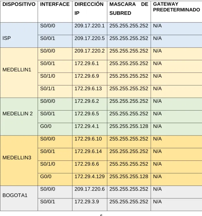
TABLA DE DIRECCIONAMIENTO IP
DISPOSITIVO INTERFACE DIRECCIÓN IP
MASCARA DE SUBRED
GATEWAY
PREDETERMINADO
ISP
S0/0/0 209.17.220.1 255.255.255.252 N/A
S0/0/1 209.17.220.5 255.255.255.252 N/A
MEDELLIN1
S0/0/0 209.17.220.2 255.255.255.252 N/A
S0/0/1 172.29.6.1 255.255.255.252 N/A
S0/1/0 172.29.6.9 255.255.255.252 N/A
S0/1/1 172.29.6.13 255.255.255.252 N/A
MEDELLIN 2
S0/0/0 172.29.6.2 255.255.255.252 N/A
S0/0/1 172.29.6.5 255.255.255.252 N/A
G0/0 172.29.4.1 255.255.255.128 N/A
MEDELLIN3
S0/0/0 172.29.6.10 255.255.255.252 N/A
S0/0/1 172.29.6.14 255.255.255.252 N/A
S0/1/0 172.29.6.6 255.255.255.252 N/A
G0/0 172.29.4.129 255.255.255.128 N/A
BOGOTA1
S0/0/0 209.17.220.6 255.255.255.252 N/A
7 Desarrollo
Como trabajo inicial se debe realizar lo siguiente:
• Realizar las rutinas de diagnóstico y dejar los equipos listos para su configuración (asignar nombres de equipos, asignar claves de seguridad, etc).
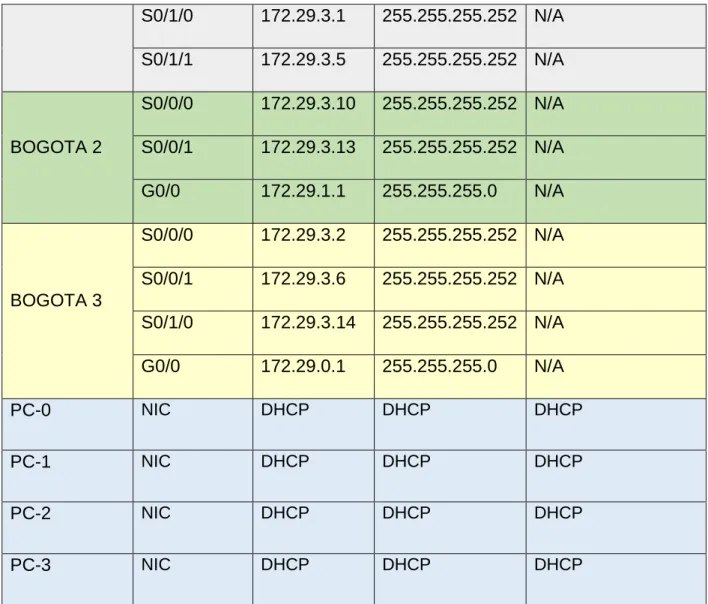
S0/1/0 172.29.3.1 255.255.255.252 N/A
S0/1/1 172.29.3.5 255.255.255.252 N/A
BOGOTA 2
S0/0/0 172.29.3.10 255.255.255.252 N/A
S0/0/1 172.29.3.13 255.255.255.252 N/A
G0/0 172.29.1.1 255.255.255.0 N/A
BOGOTA 3
S0/0/0 172.29.3.2 255.255.255.252 N/A
S0/0/1 172.29.3.6 255.255.255.252 N/A
S0/1/0 172.29.3.14 255.255.255.252 N/A
G0/0 172.29.0.1 255.255.255.0 N/A
PC-0 NIC DHCP DHCP DHCP
PC-1 NIC DHCP DHCP DHCP
PC-2 NIC DHCP DHCP DHCP
PC-3 NIC DHCP DHCP DHCP
8
• Realizar la conexión fisica de los equipos con base en la topología de red
Figura N°. 2 conexión fisica de los equipos
Router(config)#hostname ISP ISP(config)#enable se
% Incomplete command.
ISP(config)#enable secret cisco
ISP(config)#service password-encryption
ISP(config)#banner motd "solo acceso autorizado" ISP(config)#line console 0
ISP(config-line)#password class ISP(config-line)#password class ISP(config-line)#login
ISP(config-line)#exit ISP(config)#line vty 0 15
ISP(config-line)#password class ISP(config-line)#login
ISP(config-line)#exit ISP(config)#
ISP r(config)#int s0/0/0
9 ISP (config-if)#no shutdown
%LINK-5-CHANGED: Interface Serial0/0/0, changed state to down ISP (config-if)#int s0/0/1
ISP (config-if)#ip address 209.17.220.5 255.255.255.252 ISP (config-if)#clock rate 4000000
ISP (config-if)#no shutdown
%LINK-5-CHANGED: Interface Serial0/0/1, changed state to down ISP (config-if)#
Router>enable
Router#configure terminal
Enter configuration commands, one per line. End with CNTL/Z. Router(config)#hostname MEDELLIN1
MEDELLIN1(config)#enable secret cisco
MEDELLIN1(config)#service password-encryption
MEDELLIN1(config)#banner motd "solo acceso autorizado" MEDELLIN1(config)#line console 0
MEDELLIN1(config-line)#password class MEDELLIN1(config-line)#password class MEDELLIN1(config-line)#login
MEDELLIN1(config-line)#exit MEDELLIN1(config)#line vty 0 15
MEDELLIN1(config-line)#password class MEDELLIN1(config-line)#login
MEDELLIN1(config-line)#exit MEDELLIN1(config)#int s0/0/0
MEDELLIN1(config-if)#ip address 209.17.220.2 255.255.255.252 MEDELLIN1(config-if)#no shutdown
MEDELLIN1(config-if)#
%LINK-5-CHANGED: Interface Serial0/0/0, changed state to up
%LINEPROTO-5-UPDOWN: Line protocol on Interface Serial0/0/0, changed state to up MEDELLIN1(config-if)#int s0/0/1
MEDELLIN1(config-if)#ip address 172.29.6.1 255.255.255.252 MEDELLIN1(config-if)#clock rate 4000000
MEDELLIN1(config-if)#no shutdown
%LINK-5-CHANGED: Interface Serial0/0/1, changed state to down MEDELLIN1(config-if)#int s0/1/0
MEDELLIN1(config-if)#ip address 172.29.6.9 255.255.255.252 MEDELLIN1(config-if)#clock rate 4000000
MEDELLIN1(config-if)#no shutdown
10 MEDELLIN1(config-if)#int s0/1/1
MEDELLIN1(config-if)#ip address 172.29.6.13 255.255.255.252 MEDELLIN1(config-if)#clock rate 4000000
MEDELLIN1(config-if)#no shutdown
%LINK-5-CHANGED: Interface Serial0/1/1, changed state to down MEDELLIN1(config-if)#
Router>enable
Router#configure terminal
Enter configuration commands, one per line. End with CNTL/Z. Router(config)#hostname MEDELLIN2
MEDELLIN2(config)#enable secret cisc0 MEDELLIN2(config)#enable secret cisco
MEDELLIN2(config)#service password-encryption
MEDELLIN2(config)#banner motd "solo acceso autorizado" MEDELLIN2(config)#line console 0
MEDELLIN2(config-line)#password class MEDELLIN2(config-line)#password class MEDELLIN2(config-line)#login
MEDELLIN2(config-line)#exit MEDELLIN2(config)#line vty 0 15
MEDELLIN2(config-line)#password class MEDELLIN2(config-line)#login
MEDELLIN2(config-line)#exit MEDELLIN2(config)#int s0/0/0
MEDELLIN2(config-if)#ip address 172.29.6.2 255.255.255.252 MEDELLIN2(config-if)#no shutdown
MEDELLIN2(config-if)#
%LINK-5-CHANGED: Interface Serial0/0/0, changed state to up
%LINEPROTO-5-UPDOWN: Line protocol on Interface Serial0/0/0, changed state to up MEDELLIN2(config-if)#int s0/0/1
MEDELLIN2(config-if)#ip address 172.29.6.5 255.255.255.252 MEDELLIN2(config-if)#clock rate 4000000
MEDELLIN2(config-if)#no shutdown MEDELLIN2(config-if)#
%LINK-5-CHANGED: Interface Serial0/0/0, changed state to up MEDELLIN2(config-if)#int g0/0
MEDELLIN2(config-if)#ip address 172.29.4.1 255.255.255.128 MEDELLIN2(config-if)#no shutdown
MEDELLIN2(config-if)#
11 Router>enable
Router#configure terminal
Enter configuration commands, one per line. End with CNTL/Z. Router(config)#hostname MEDELLIN3
MEDELLIN3(config)#enable secret cisco
MEDELLIN3(config)#service password-encryption
MEDELLIN3(config)#banner motd "solo acceso autorizado" MEDELLIN3(config)#line console 0
MEDELLIN3(config-line)#password class MEDELLIN3(config-line)#password class MEDELLIN3(config-line)#login
MEDELLIN3(config-line)#exit MEDELLIN3(config)#line vty 0 15
MEDELLIN3(config-line)#password class MEDELLIN3(config-line)#login
MEDELLIN3(config-line)#exit MEDELLIN3(config)#int s0/0/0
MEDELLIN3(config-if)#ip address 172.29.6.10 255.255.255.252 MEDELLIN3(config-if)#no shutdown
MEDELLIN3(config-if)#
%LINK-5-CHANGED: Interface Serial0/0/0, changed state to up
%LINEPROTO-5-UPDOWN: Line protocol on Interface Serial0/0/0, changed state to up
MEDELLIN3(config-if)#int s0/0/1
MEDELLIN3(config-if)#ip address 172.29.6.14 255.255.255.252 MEDELLIN3(config-if)#no shutdown
MEDELLIN3(config-if)#
%LINK-5-CHANGED: Interface Serial0/0/1, changed state to up
%LINEPROTO-5-UPDOWN: Line protocol on Interface Serial0/0/1, changed state to up MEDELLIN3(config-if)#int s0/1/0
MEDELLIN3(config-if)#ip address 172.29.6.6 255.255.255.252 MEDELLIN3(config-if)#no shutdown
%LINK-5-CHANGED: Interface Serial0/1/0, changed state to down MEDELLIN3(config-if)#int g0/0
MEDELLIN3(config-if)#ip address 172.29.4.129 255.255.255.128 MEDELLIN3(config-if)#no shutdown
MEDELLIN3(config-if)#
12
%LINEPROTO-5-UPDOWN: Line protocol on Interface GigabitEthernet0/0, changed state to up
Router>enable
Router#configure terminal
Enter configuration commands, one per line. End with CNTL/Z. Router(config)#hostname BOGOTA1
BOGOTA1(config)#enable secret cisco
BOGOTA1(config)#service password-encryption
BOGOTA1(config)#banner motd "solo acceso autorizado" BOGOTA1(config)#line console 0
BOGOTA1(config-line)#password class BOGOTA1(config-line)#password class BOGOTA1(config-line)#login
BOGOTA1(config-line)#exit BOGOTA1(config)#line vty 0 15
BOGOTA1(config-line)#password class BOGOTA1(config-line)#login
BOGOTA1(config-line)#exit BOGOTA1(config)#int s0/0/0
BOGOTA1(config-if)#ip address 209.17.220.6 255.255.255.252 BOGOTA1(config-if)#no shutdown
BOGOTA1(config-if)#
%LINK-5-CHANGED: Interface Serial0/0/0, changed state to up
%LINEPROTO-5-UPDOWN: Line protocol on Interface Serial0/0/0, changed state to up BOGOTA1(config-if)#int s0/0/1
BOGOTA1(config-if)#ip address 172.29.3.9 255.255.255.252 BOGOTA1(config-if)#clock rate 4000000
BOGOTA1(config-if)#no shutdown
%LINK-5-CHANGED: Interface Serial0/0/1, changed state to down BOGOTA1(config-if)#int s0/1/0
BOGOTA1(config-if)#ip address 172.29.3.1 255.255.255.252 BOGOTA1(config-if)#clock rate 4000000
BOGOTA1(config-if)#no shutdown
%LINK-5-CHANGED: Interface Serial0/1/0, changed state to down BOGOTA1(config-if)#
BOGOTA1(config-if)#int s0/1/1
BOGOTA1(config-if)#ip address 172.29.3.5 255.255.255.252 BOGOTA1(config-if)#clock rate 4000000
BOGOTA1(config-if)#no shutdown
13 Router>enable
Router#configure terminal
Enter configuration commands, one per line. End with CNTL/Z. Router(config)#hostname BOGOTA2
BOGOTA2(config)#enable secret cisco
BOGOTA2(config)#service password-encryption
BOGOTA2(config)#banner motd "solo acceso autorizado" BOGOTA2(config)#line console 0
BOGOTA2(config-line)#password class BOGOTA2(config-line)#password class BOGOTA2(config-line)#login
BOGOTA2(config-line)#exit BOGOTA2(config)#line vty 0 15
BOGOTA2(config-line)#password class BOGOTA2(config-line)#login
BOGOTA2(config-line)#exit BOGOTA2(config)#int s0/0/0
BOGOTA2(config-if)#ip address 172.29.3.10 255.255.255.252 BOGOTA2(config-if)#no shutdown
BOGOTA2(config-if)#
%LINK-5-CHANGED: Interface Serial0/0/0, changed state to up
%LINEPROTO-5-UPDOWN: Line protocol on Interface Serial0/0/0, changed state to up BOGOTA2(config-if)#int s0/0/1
BOGOTA2(config-if)#ip address 172.29.3.13 255.255.255.252 BOGOTA2(config-if)#clock rate 4000000
BOGOTA2(config-if)#no shutdown
%LINK-5-CHANGED: Interface Serial0/0/1, changed state to down BOGOTA2(config-if)#int g0/0
BOGOTA2(config-if)#ip address 172.29.1.1 255.255.255.0 BOGOTA2(config-if)#no shutdown
BOGOTA2(config-if)#
%LINK-5-CHANGED: Interface GigabitEthernet0/0, changed state to up
%LINEPROTO-5-UPDOWN: Line protocol on Interface GigabitEthernet0/0, changed state to up
Router>enable
Router#configure terminal
14 BOGOTA3(config)#enable secret cisco
BOGOTA3(config)#service password-encryption
BOGOTA3(config)#banner motd "solo acceso autorizado" BOGOTA3(config)#line console 0
BOGOTA3(config-line)#password class BOGOTA3(config-line)#password class BOGOTA3(config-line)#login
BOGOTA3(config-line)#exit BOGOTA3(config)#line vty 0 15
BOGOTA3(config-line)#password class BOGOTA3(config-line)#login
BOGOTA3(config-line)#exit BOGOTA3(config)#int s0/0/0
BOGOTA3(config-if)#ip address 172.29.3.2 255.255.255.252 BOGOTA3(config-if)#no shutdown
BOGOTA3(config-if)#
%LINK-5-CHANGED: Interface Serial0/0/0, changed state to up
%LINEPROTO-5-UPDOWN: Line protocol on Interface Serial0/0/0, changed state to up BOGOTA3(config-if)#int s0/0/1
BOGOTA3(config-if)#ip address 172.29.3.6 255.255.255.252 BOGOTA3(config-if)#no shutdown
BOGOTA3(config-if)#
%LINK-5-CHANGED: Interface Serial0/0/1, changed state to up
%LINEPROTO-5-UPDOWN: Line protocol on Interface Serial0/0/1, changed state to up BOGOTA3(config-if)#int g0/0
BOGOTA3(config-if)#ip address 172.29.0.1 255.255.255.0 BOGOTA3(config-if)#no shutdown
BOGOTA3(config)#int s0/1/0
BOGOTA3(config-if)#ip address 172.29.3.14 255.255.255.252 BOGOTA3(config-if)#no shutdown
Configurar la topología de red, de acuerdo con las siguientes especificaciones.
1.1.1. Parte 1: Configuración del enrutamiento
a. Configurar el enrutamiento en la red usando el protocolo RIP versión 2, declare la red principal, desactive la sumarización automática.
15 Password:
Password:
MEDELLIN1#configure terminal
Enter configuration commands, one per line. End with CNTL/Z. MEDELLIN1(config)#router rip
MEDELLIN1(config-router)#version 2
MEDELLIN1(config-router)#no auto-summaryl
MEDELLIN1(config-router)#do show ip route connected C 172.29.6.0/30 is directly connected, Serial0/0/1
C 172.29.6.8/30 is directly connected, Serial0/1/0 C 172.29.6.12/30 is directly connected, Serial0/1/1 C 209.17.220.0/30 is directly connected, Serial0/0/0
MEDELLIN1(config-router)#network 172.29.6.0 MEDELLIN1(config-router)#network 172.29.6.8 MEDELLIN1(config-router)#network 172.29.6.12 MEDELLIN1(config-router)#passive-interface s0/0/0 MEDELLIN1(config-router)# MEDELLIN2(config)#router rip MEDELLIN2(config-router)#version 2 MEDELLIN2(config-router)#no auto-summary
MEDELLIN2(config-router)#do show ip route connected C 172.29.4.0/25 is directly connected, GigabitEthernet0/0 C 172.29.6.0/30 is directly connected, Serial0/0/0
C 172.29.6.4/30 is directly connected, Serial0/0/1
MEDELLIN2(config-router)#network 172.29.4.0 MEDELLIN2(config-router)#network 172.29.6.0 MEDELLIN2(config-router)#network 172.29.6.4 MEDELLIN2(config-router)#passive-interface g0/0 MEDELLIN2(config-router)#exit MEDELLIN2(config)# MEDELLIN3(config)#router rip MEDELLIN3(config-router)#version 2 MEDELLIN3(config-router)#no auto-summary
MEDELLIN3(config-router)#do show ip route connected C 172.29.4.128/25 is directly connected, GigabitEthernet0/0 C 172.29.6.4/30 is directly connected, Serial0/1/0
16 MEDELLIN3(config-router)#network 172.29.4.128 MEDELLIN3(config-router)#network 172.29.6.4 MEDELLIN3(config-router)#network 172.29.6.8 MEDELLIN3(config-router)#network 172.29.6.12 MEDELLIN3(config-router)#passive-interface g0/0 MEDELLIN3(config-router)#exit MEDELLIN3(config)# BOGOTA1(config)#router rip BOGOTA1(config-router)#router rip BOGOTA1(config-router)#version 2 BOGOTA1(config-router)#no auto-summary
BOGOTA1(config-router)#do show ip route connected C 172.29.3.0/30 is directly connected, Serial0/1/0 C 172.29.3.4/30 is directly connected, Serial0/1/1 C 172.29.3.8/30 is directly connected, Serial0/0/1 C 209.17.220.4/30 is directly connected, Serial0/0/0
BOGOTA1(config-router)#network 172.29.3.0 BOGOTA1(config-router)#network 172.29.3.4 BOGOTA1(config-router)#network 172.29.3.8 BOGOTA1(config-router)#passive-interface s0/0/0 BOGOTA1(config-router)# BOGOTA2#configure terminal
Enter configuration commands, one per line. End with CNTL/Z. BOGOTA2(config)#router rip
BOGOTA2(config-router)#version 2
BOGOTA2(config-router)#no auto-summary
BOGOTA2(config-router)#do show ip route connected C 172.29.1.0/24 is directly connected, GigabitEthernet0/0 C 172.29.3.8/30 is directly connected, Serial0/0/0
C 172.29.3.12/30 is directly connected, Serial0/0/1
17
Enter configuration commands, one per line. End with CNTL/Z. BOGOTA3(config)#router rip
BOGOTA3(config-router)#version 2
BOGOTA3(config-router)#no auto-summary
BOGOTA3(config-router)#do show ip route connected C 172.29.0.0/24 is directly connected, GigabitEthernet0/0 C 172.29.3.0/30 is directly connected, Serial0/0/0
C 172.29.3.4/30 is directly connected, Serial0/0/1 C 172.29.3.12/30 is directly connected, Serial0/1/0
BOGOTA3(config-router)#network 172.29.0.0 BOGOTA3(config-router)#network 172.29.3.0 BOGOTA3(config-router)#network 172.29.3.4 BOGOTA3(config-router)#network 172.29.3.12 BOGOTA3(config-router)#passive-interface g0/0 BOGOTA3(config-router)#
b. Los routers Bogota1 y Medellín deberán añadir a su configuración de enrutamiento una ruta por defecto hacia el ISP y, a su vez, redistribuirla dentro de las publicaciones de RIP.
MEDELLIN1(config)#ip route 0.0.0.0 0.0.0.0 209.17.220.1 MEDELLIN1(config)#router rip
MEDELLIN1(config-router)#default-information originate MEDELLIN1(config-router)#
BOGOTA1#configure terminal
Enter configuration commands, one per line. End with CNTL/Z. BOGOTA1(config)#ip route 0.0.0.0 0.0.0.0 209.17.220.5
BOGOTA1(config)#default-information originate BOGOTA1(config)#router rip
18
c. El router ISP deberá tener una ruta estática dirigida hacia cada red interna de Bogotá y Medellín para el caso se sumarizan las subredes de cada uno a /22.
ISP#configure terminal
Enter configuration commands, one per line. End with CNTL/Z. ISP(config)#ip route 172.29.4.0 255.255.252.0 209.17.220.2 ISP(config)#ip route 172.29.0.0 255.255.252.0 209.17.220.6 ISP(config)#
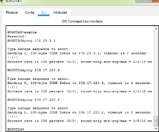
1.1.2. Parte 2: Tabla de Enrutamiento.
a. Verificar la tabla de enrutamiento en cada uno de los routers para comprobar las redes y sus rutas.
Figura N°. 3 Verificando enrutamiento
19
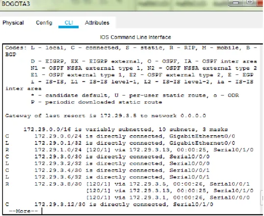
c. Obsérvese en los routers Bogotá1 y Medellín1 cierta similitud por su ubicación, por tener dos enlaces de conexión hacia otro router y por la ruta por defecto que manejan.
d. Los routers Medellín2 y Bogotá2 también presentan redes conectadas directamente y recibidas mediante RIP.
e. Las tablas de los routers restantes deben permitir visualizar rutas redundantes para el caso de la ruta por defecto.
f. El router ISP solo debe indicar sus rutas estáticas adicionales a las directamente conectadas.
Figura N°. 4 Verificando redes conectadas directamente
20
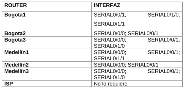
a. Para no propagar las publicaciones por interfaces que no lo requieran se debe deshabilitar la propagación del protocolo RIP, en la siguiente tabla se indican las interfaces de cada router que no necesitan desactivación.
ROUTER INTERFAZ
Bogota1 SERIAL0/0/1; SERIAL0/1/0;
SERIAL0/1/1
Bogota2 SERIAL0/0/0; SERIAL0/0/1
Bogota3 SERIAL0/0/0; SERIAL0/0/1;
SERIAL0/1/0
Medellín1 SERIAL0/0/0; SERIAL0/0/1;
SERIAL0/1/1
Medellín2 SERIAL0/0/0; SERIAL0/0/1
Medellín3 SERIAL0/0/0; SERIAL0/0/1;
SERIAL0/1/0
ISP No lo requiere
Tabla N°. 2 Interfaces de los Routers
1.1.4. Parte 4: Verificación del protocolo RIP.
a. Verificar y documentar las opciones de enrutamiento configuradas en los routers, como el passive interface para la conexión hacia el ISP, la versión de RIP y las interfaces que participan de la publicación entre otros datos.
b. Verificar y documentar la base de datos de RIP de cada router, donde se informa de manera detallada de todas las rutas hacia cada red.
1.1.5. Parte 5: Configurar encapsulamiento y autenticación PPP.
a. Según la topología se requiere que el enlace Medellín1 con ISP sea configurado con autenticación PAT.
21 Password:
ISP#configure terminal
Enter configuration commands, one per line. End with CNTL/Z. ISP(config)#username MEDELLIN1 password cisco
ISP(config)#interface s0/0/0 ISP(config-if)#
%LINEPROTO-5-UPDOWN: Line protocol on Interface Serial0/0/0, changed state to down
ISP(config-if)#encapsulation ppp ISP(config-if)#ppp authentication pap
ISP(config-if)#ppp pap sent-username ISP password cisco ISP(config-if)#end
ISP#
%SYS-5-CONFIG_I: Configured from console by console
MEDELLIN1#configure terminal
Enter configuration commands, one per line. End with CNTL/Z. MEDELLIN1(config)#username ISP password cisco
MEDELLIN1(config)#int s0/0/0
MEDELLIN1(config-if)#encapsulation ppp MEDELLIN1(config-if)#ppp authentication pap
MEDELLIN1(config-if)#ppp pap sent-username MEDELLIN1 password cisco MEDELLIN1(config-if)#end
MEDELLIN1#
%SYS-5-CONFIG_I: Configured from console by console
b. El enlace Bogotá1 con ISP se debe configurar con autenticación CHAT.
ISP#configure terminal
Enter configuration commands, one per line. End with CNTL/Z. ISP(config)#username BOGOTA1 password cisco
ISP(config)#int s0/0/0 ISP(config-if)#exit ISP(config)#int s0/0/1
ISP(config-if)#encapsulation ppp ISP(config-if)#
%LINEPROTO-5-UPDOWN: Line protocol on Interface Serial0/0/1, changed state to down
22 ISP(config)#
BOGOTA1#configure terminal
Enter configuration commands, one per line. End with CNTL/Z. BOGOTA1(config)#username ISP password cisco
BOGOTA1(config)#int s0/0/0
BOGOTA1(config-if)#encapsulation ppp BOGOTA1(config-if)#ppp authentication chap BOGOTA1(config-if)#exit
BOGOTA1(config)#
1.1.6. Parte 6: Configuración de PAT.
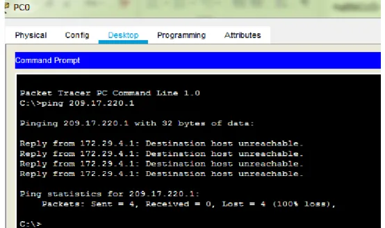
a. En la topología, si se activa NAT en cada equipo de salida (Bogotá1 y Medellín1), los routers internos de una ciudad no podrán llegar hasta los routers internos en el
otro extremo, sólo existirá comunicación hasta los routers Bogotá1, ISP y Medellín1.
b. Después de verificar lo indicado en el paso anterior proceda a configurar el NAT en el router Medellín1. Compruebe que la traducción de direcciones indique las interfaces de entrada y de salida. Al realizar una prueba de ping, la dirección debe ser traducida automáticamente a la dirección de la interfaz serial 0/1/0 del router Medellín1, cómo diferente puerto.
c. Proceda a configurar el NAT en el router Bogotá1. Compruebe que la traducción de direcciones indique las interfaces de entrada y de salida. Al realizar una prueba de ping, la dirección debe ser traducida automáticamente a la dirección de la interfaz serial 0/1/0 del router Bogotá1, cómo diferente puerto.
MEDELLIN1#configure terminal
Enter configuration commands, one per line. End with CNTL/Z.
23 MEDELLIN1(config)#int s0/0/0
MEDELLIN1(config-if)#ip nat outside MEDELLIN1(config-if)#int s0/0/1 MEDELLIN1(config-if)#ip nat inside MEDELLIN1(config-if)#int s0/1/0 MEDELLIN1(config-if)#ip nat inside MEDELLIN1(config-if)#int s0/1/1 MEDELLIN1(config-if)#ip nat inside MEDELLIN1(config-if)#
BOGOTA1#configure terminal
Enter configuration commands, one per line. End with CNTL/Z.
BOGOTA1(config)#ip nat inside source list 1 interface s0/0/0 overload BOGOTA1(config)#access-list 1 permit 172.29.0.0 0.0.3.255
BOGOTA1(config)#int s0/0/0 BOGOTA1(config-if)#ip nat outside BOGOTA1(config-if)#int s0/0/1 BOGOTA1(config-if)#ip nat inside BOGOTA1(config-if)#int s0/1/0 BOGOTA1(config-if)#ip nat inside BOGOTA1(config-if)#int s0/1/1 BOGOTA1(config-if)#ip nat inside BOGOTA1(config-if)#
24 Figura N°. 6 Verificando conectividad- PC2
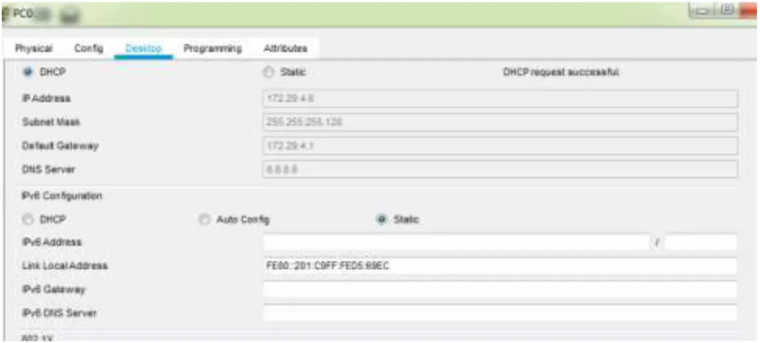
1.1.7. Parte 7: Configuración del servicio DHCP.
a. Configurar la red Medellín2 y Medellín3 donde el router Medellín 2 debe ser el servidor DHCP para ambas redes LAN.
MEDELLIN2#configure terminal
Enter configuration commands, one per line. End with CNTL/Z. MEDELLIN2(config)#ip dhcp excluded-address
% Incomplete command.
25
MEDELLIN2(config)#ip dhcp excluded-address 172.29.4.129 172.29.4.133 MEDELLIN2(config)#ip dhcp pool MEDELLLIN2
MEDELLIN2(dhcp-config)#network 172.29.4.0 255.255.255.128 MEDELLIN2(dhcp-config)#default-router 172.29.4.1
MEDELLIN2(dhcp-config)#dns-server 8.8.8.8 MEDELLIN2(dhcp-config)#exit
MEDELLIN2(config)#
MEDELLIN2(config)#ip dhcp pool MEDELLLIN3
MEDELLIN2(dhcp-config)#network 172.29.4.128 255.255.255.128 MEDELLIN2(dhcp-config)#default-router 172.29.4.129
MEDELLIN2(dhcp-config)#dns-server 8.8.8.8 MEDELLIN2(dhcp-config)#exit
MEDELLIN2(config)#
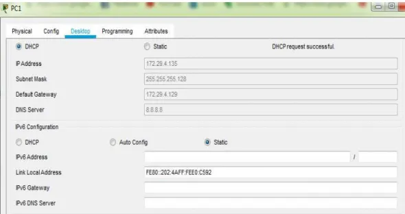
b. El router Medellín3 deberá habilitar el paso de los mensajes broadcast hacia la IP del router Medellín2.
c. Configurar la red Bogotá2 y Bogotá3 donde el router Medellín2 debe ser el servidor DHCP para ambas redes LAN.
d. Configure el router Bogotá1 para que habilite el paso de los mensajes Broadcast hacia la IP del router Bogotá2.
26 MEDELLIN3#configure terminal
Enter configuration commands, one per line. End with CNTL/Z. MEDELLIN3(config)#int g0/0
MEDELLIN3(config-if)#ip helper-address 172.29.6.5 MEDELLIN3(config-if)#
Figura N°. 8 Configuración DHCP- PC1
BOGOTA2#configure terminal
Enter configuration commands, one per line. End with CNTL/Z. BOGOTA2(config)#ip dhcp excluded-address 172.29.1.1 172.29.1.5 BOGOTA2(config)#ip dhcp excluded-address 172.29.0.1 172.29.0.5 BOGOTA2(config)#ip dhcp pool BOGOTA2
BOGOTA2(dhcp-config)#network 172.29.1.0 255.255.255.0 BOGOTA2(dhcp-config)#default-router 172.29.1.1
BOGOTA2(dhcp-config)#dns-server 8.8.8.8 BOGOTA2(dhcp-config)#ip dhcp pool BOGOTA3
BOGOTA2(dhcp-config)#network 172.29.0.0 255.255.255.0 BOGOTA2(dhcp-config)#default-router 172.29.0.1
BOGOTA2(dhcp-config)#dns-server 8.8.8.8 BOGOTA2(dhcp-config)#exit
27 BOGOTA3#configure terminal
Enter configuration commands, one per line. End with CNTL/Z. BOGOTA3(config)#int g0/0
BOGOTA3(config-if)#ip helper-address 172.29.3.13 BOGOTA3(config-if)#
29
1.2. ESCENARIO 2
Una empresa de Tecnología posee tres sucursales distribuidas en las ciudades de Miami, Bogotá y Buenos Aires, en donde el estudiante será el administrador de la red, el cual deberá configurar e interconectar entre sí cada uno de los dispositivos que forman parte del escenario, acorde con los lineamientos establecidos para el direccionamiento IP, protocolos de enrutamiento y demás aspectos que forman parte de la topología de red.
Figura N°. 11 Topología de Red- Escenario 2
30 Figura N°. 12 Conexión física de los dispositivos Tabla de Direccionamiento IP
CONFIGURACIÓN BÁSICA -R1
Dispositivo Interfaz Dirección IP Máscara de
subred
Gateway
predeterminado
R1 G0/1 192.168.99.1 255.255.255.0 N/A
S0/0/0 172.31.21.1 255.255.255.252 N/A
R2
S0/0/1 172.31.21.2 255.255.255.252 N/A S/0/0/0 172.31.23.1 255.255.255.252 N/A Lo0 10.10.10.10 255.255.255.255 N/A
R3
S0/0/1 172.31.23.2 255.255.255.252 N/A Lo4 192.168.4.1 255.255.255.0 N/A Lo5 192.168.5.1 255.255.255.0 N/A Lo6 192.168.6.1 255.255.255.0 N/A
PC-A NIC DHCP DHCP DHCP
PC-C NIC DHCP DHCP DHCP
31 Figura N°. 13 Configuración IP- Internet-PC
Router>enable Router#configure ter
Enter configuration commands, one per line. End with CNTL/Z. Router(config)#no ip domain-lookup
Router(config)#hostname BOGOTA BOGOTA (config)#enable secret class BOGOTA (config)#line console 0 BOGOTA (config-line)#password cisco BOGOTA (config-line)#login
BOGOTA (config-line)#line vty 0 15 BOGOTA (config-line)#password cisco BOGOTA (config-line)#login
BOGOTA (config-line)#service password-encryption BOGOTA (config)#banner motd "solo acceso autorizado"
BOGOTA (config)#
BOGOTA (config)#interface s0/0/0
BOGOTA (config-if)#ip address 172.31.21.1 255.255.255.252 BOGOTA (config-if)#clock rate 128000
BOGOTA (config-if)#no shutdown
%LINK-5-CHANGED: Interface Serial0/0/0, changed state to down BOGOTA (config-if)#description Bogota
CONFIGURACIÓN BÁSICA -R2 Router>enable
32
Enter configuration commands, one per line. End with CNTL/Z. Router(config)#no ip domain-lookup
Router(config)#hostname MIAMI MIAMI (config)#enable secret class MIAMI (config)#line console 0 MIAMI (config-line)#password cisco MIAMI (config-line)#login
MIAMI (config-line)#line vty 0 15 MIAMI (config-line)#password cisco MIAMI (config-line)#login
MIAMI (config-line)#service password-encryption MIAMI (config)#banner motd "solo acceso autorizado" MIAMI (config)#
CONFIGURACIÓN BÁSICA -R3
Router(config)#hostname BUENOSAIRES BUENOSAIRES(config)#enable secret class BUENOSAIRES(config)#line console 0 BUENOSAIRES(config-line)#password cisco BUENOSAIRES(config-line)#login
BUENOSAIRES(config-line)#line vty 0 15 BUENOSAIRES(config-line)#password cisco BUENOSAIRES(config-line)#login
BUENOSAIRES(config-line)#service password-encryption BUENOSAIRES(config)#banner motd "solo acceso autorizado" BUENOSAIRES(config)#
CONFIGURACIÓN BÁSICA -S1
Switch>enable Switch#conf ter
Enter configuration commands, one per line. End with CNTL/Z. Switch(config)#no ip domain-lookup
Switch(config)#hostname S1 S1(config)#enable secret class S1(config)#line console 0 S1(config-line)#password cisco S1(config-line)#login
S1(config-line)#exit
33 S1(config)#banner motd "solo acceso autorizado"
S1(config)#
CONFIGURACIÓN BÁSICA -S3 Switch>enable
Switch#conf ter
Enter configuration commands, one per line. End with CNTL/Z. Switch(config)#no ip domain-lookup
Switch(config)#hostname S3 S3(config)#enable secret class S3(config)#line console 0 S3(config-line)#password cisco S3(config-line)#login
S3(config)#service password-encryption
S3(config)#banner motd "solo acceso autorizado" S3(config)#
Tabla de VLANs
VLAN DIRECCIONAMIENTO NOMBRE
30 192.168.30.0/24 Administración
40 192.168.40.0/24 Mercadeo
200 192.168.200.0/24 Mantenimiento
Tabla N°. 3 Tabla de VLANS -Dependencias
VLANS S1
Enter configuration commands, one per line. End with CNTL/Z. S1(config)#vlan 30
S1(config-vlan)#name Administracion S1(config-vlan)#vlan 40
S1(config-vlan)#name Mercadeo S1(config-vlan)#vlan 200
34 S1(config-vlan)#
Mode Trunk S1 F0/3 S1(config-vlan)#int f0/3
S1(config-if)#switchport mode trunk S1(config-if)#
%LINEPROTO-5-UPDOWN: Line protocol on Interface FastEthernet0/3, changed state to down
%LINEPROTO-5-UPDOWN: Line protocol on Interface FastEthernet0/3, changed state to up
S1(config-if)#switchport trunk native vlan 1 S1(config-if)#
Mode Trunk S1 F0/24
S1(config)#int f0/24
S1(config-if)#switchport mode trunk
S1(config-if)#switchport trunk native vlan 1 S1(config-if)#no shutdown
S1(config-if)#
Puertos en mode Access S1 S1(config)#int f0/1
S1(config-if)#switchport trunk native vlan 1 S1(config-if)#int range fa0/1-2, fa0/4-24, g0/1-2 S1(config-if-range)#switchport mode access S1(config-if-range)#
Asignación F0/1 y apagados puertos S3
S1(config-if-range)#switchport access vlan 30 S1(config-if-range)#int range fa0/2, fa0/4-24, g0/1-2 S1(config-if-range)#shutdown
35 S1(config-if-range)#int vlan 200
S1(config-if)#
%LINK-5-CHANGED: Interface Vlan200, changed state to up
%LINEPROTO-5-UPDOWN: Line protocol on Interface Vlan200, changed state to up
S1(config-if)#ip address 192.168.99.2 255.255.255.0 S1(config-if)#no shutdown
S1(config-if)# VLANs S3 S3(config)#vlan 30
S3(config-vlan)#name Administracion S3(config-vlan)#vlan 40
S3(config-vlan)#name Mercadeo S3(config-vlan)#vlan 200
S3(config-vlan)#name Mantenimiento S3(config-vlan)#
VLAN Mantenimiento S3
S3(config-vlan)#int vlan 200 S3(config-if)#
%LINK-5-CHANGED: Interface Vlan200, changed state to up
%LINEPROTO-5-UPDOWN: Line protocol on Interface Vlan200, changed state to up
S3(config-if)#ip address 192.168.99.3 255.255.255.0 S3(config-if)#no shutdown
S3(config-if)#
Puerta de enlace predeterminada S3 – VLAN Mantenimiento
S3(config-if)#exit
S3(config)#ip default-gateway 192.168.99.1 S3(config)#
36 S3(config)#int f0/3
S3(config-if)#switchport mode trunk
S3(config-if)#switchport trunk native vlan 1 S3(config-if)#no shutdown
S3(config-if)#
Puertos en mode Access S3
S3(config-if)#int range fa0/1-2, fa0/4-24, g0/1-2 S3(config-if-range)#switchport mode access S3(config-if-range)#no shutdown
Asignación F0/1 y apagados puertos S3
S3(config)#int f0/1
S3(config-if)#switchport mode access S3(config-if)#switchport access vlan 40 S3(config-if)#int range fa0/2, fa0/4-24, g0/1-2 S3(config-if-range)#shutdown
%LINK-5-CHANGED: Interface FastEthernet0/2, changed state to administratively down
Configurar en “BOGOTÁ” la conexión hacía MIAMI
S0/0/0 – R1
BOGOTA(config)#int s0/0/0
BOGOTA(config-if)#description connection a MIAMI BOGOTA(config-if)#description connection to MIAMI
BOGOTA(config-if)#ip address 172.31.21.1 255.255.255.252 BOGOTA(config-if)#clock rate 128000
BOGOTA(config-if)#no shutdown BOGOTA(config-if)#
Ruta de salida S0/0/0 – R1
37 BOGOTA(config)#
Configurar en “MIAMI” las siguientes interfaces
✓ Configurar conexión hacía BOGOTA
✓ Configurar conexión hacía BUENOS AIRES
✓ Establecer conexión hacia PC-Internet
✓ Establecer conexión hacía Web Server
Interface S0/0/1 – R2 MIAMI#confi ter
Enter configuration commands, one per line. End with CNTL/Z. MIAMI(config)#int s0/0/1
MIAMI(config-if)#description connection to Bogota
MIAMI(config-if)#ip address 172.31.21.2 255.255.255.252 MIAMI(config-if)#no shutdown
MIAMI(config-if)#
%LINK-5-CHANGED: Interface Serial0/0/1, changed state to up
%LINEPROTO-5-UPDOWN: Line protocol on Interface Serial0/0/1, changed state to up
Interface S0/0/0 – R2
MIAMI(config-if)#int s0/0/0
MIAMI(config-if)#description connection to Buenos Aires MIAMI(config-if)#ip address 172.31.23.1 255.255.255.252 MIAMI(config-if)#clock rate 128000
This command applies only to DCE interfaces MIAMI(config-if)#no shutdown
%LINK-5-CHANGED: Interface Serial0/0/0, changed state to down MIAMI(config-if)#
38 MIAMI(config-if)#int f0/0
MIAMI(config-if)#ip address 209.165.200.225 255.255.255.248 MIAMI(config-if)#no shutdown
MIAMI(config-if)#
%LINK-5-CHANGED: Interface FastEthernet0/0, changed state to up
Interface F0/1 – R2
MIAMI(config-if)#int f0/1
MIAMI(config-if)#ip address 10.10.10.10 255.255.255.0 MIAMI(config-if)#no shutdown
MIAMI(config-if)#
%LINK-5-CHANGED: Interface FastEthernet0/0, changed state to up
Configurar en “Buenos Aires” los siguientes parámetros:
✓ Configurar la conexión hacia “MIAMI”
✓ Configurar loopbacks 4 – 5 – 6
Interface S0/0/1 – R3
BUENOSAIRES(config)#int s0/0/1
BUENOSAIRES(config-if)#description connection to MIAMI
BUENOSAIRES(config-if)#ip address 172.31.23.2 255.255.255.252 BUENOSAIRES(config-if)#no shutdown
BUENOSAIRES(config-if)#
%LINK-5-CHANGED: Interface Serial0/0/1, changed state to up
%LINEPROTO-5-UPDOWN: Line protocol on Interface Serial0/0/1, changed state to up
Loopback 4
BUENOSAIRES(config-if)#int lo4 BUENOSAIRES(config-if)#
%LINK-5-CHANGED: Interface Loopback4, changed state to up
%LINEPROTO-5-UPDOWN: Line protocol on Interface Loopback4, changed state to up BUENOSAIRES(config-if)#ip address 192.168.4.1 255.255.255.0
BUENOSAIRES(config-if)#no shutdown BUENOSAIRES(config-if)#
39 BUENOSAIRES(config-if)#int lo5
BUENOSAIRES(config-if)#
%LINK-5-CHANGED: Interface Loopback5, changed state to up
%LINEPROTO-5-UPDOWN: Line protocol on Interface Loopback5, changed state to up BUENOSAIRES(config-if)#ip address 192.168.5.1 255.255.255.0
BUENOSAIRES(config-if)#no shutdown BUENOSAIRES(config-if)#
Loopback 6
BUENOSAIRES(config-if)#int lo6 BUENOSAIRES(config-if)#
%LINK-5-CHANGED: Interface Loopback6, changed state to up
%LINEPROTO-5-UPDOWN: Line protocol on Interface Loopback6, changed state to up BUENOSAIRES(config-if)#ip address 192.168.6.1 255.255.255.0
BUENOSAIRES(config-if)#no shutdown BUENOSAIRES(config-if)#
Realizar la configuración del direccionamiento del Web Server ✓ Direccionamiento Web Server
Figura N°. 14 Direccionamiento Web Server
Configuración de seguridad Switch, VLANs, Inter-VLANs Routing
40
✓ Configure 802.1Q subinterface .30 || descripción de la conexión, asignar VLAN
Administración, asignación de la primera dirección viable a esta interface.
✓ Configure 802.1Q subinterface .40 || descripción de la conexión, asignar VLAN
Mercadeo, asignación de la primera dirección viable a esta interface.
✓ Configure 802.1Q subinterface .200 || descripción de la conexión, asignar VLAN
Mantenimiento, asignación de la primera dirección viable a esta interface. ✓ Activar la conexión hacia S1
802.1Q – R1
BOGOTA(config)#int f0/0.30
BOGOTA(config-subif)#description accounting LAN BOGOTA(config-subif)#encapsulation dot1q 30
BOGOTA(config-subif)#ip address 192.168.30.1 255.255.255.0 BOGOTA(config-subif)#int f0/0.40
BOGOTA(config-subif)#description accounting LAN BOGOTA(config-subif)#encapsulation dot1q 40
BOGOTA(config-subif)#ip address 192.168.40.1 255.255.255.0 BOGOTA(config-subif)#int f0/0.200
BOGOTA(config-subif)#description accounting LAN BOGOTA(config-subif)#encapsulation dot1q 200
BOGOTA(config-subif)#ip address 192.168.200.1 255.255.255.0 BOGOTA(config-subif)#
Interface F0/0
BOGOTA(config-subif)#int f0/0 BOGOTA(config-if)#no shutdown BOGOTA(config-if)#
%LINK-5-CHANGED: Interface FastEthernet0/0, changed state to up
%LINEPROTO-5-UPDOWN: Line protocol on Interface FastEthernet0/0, changed state to up
41
%LINEPROTO-5-UPDOWN: Line protocol on Interface FastEthernet0/0.30, changed state to up
%LINK-5-CHANGED: Interface FastEthernet0/0.40, changed state to up
%LINEPROTO-5-UPDOWN: Line protocol on Interface FastEthernet0/0.40, changed state to up
%LINK-5-CHANGED: Interface FastEthernet0/0.200, changed state to up
%LINEPROTO-5-UPDOWN: Line protocol on Interface FastEthernet0/0.200, changed state to up
Verificar Conectividad
42
Configuration Item or Task Specification
Router ID R1 1.1.1.1
Router ID R2
5.5.5.5 Router ID R3
8.8.8.8 Configurar todas las interfaces LAN como pasivas
Establecer el ancho de banda para enlaces seriales
en 256 Kb/s
Ajustar el costo en la métrica de S0/0 a 9500 Tabla N°. 4 Elementos de Configuración
1.2.2. Verificar información de OSPF
• Visualizar tablas de enrutamiento y routers conectados por OSPFv2
• Visualizar lista resumida de interfaces por OSPF en donde se ilustre el costo de cada interface
• Visualizar el OSPF Process ID, Router ID, Address summarizations, Routing Networks, and passive interfaces configuradas en cada router.
2. Configurar VLANs, Puertos troncales, puertos de acceso, encapsulamiento, Inter-VLAN Routing y Seguridad en los Switches acorde a la topología de red establecida.
3. En el Switch 3 deshabilitar DNS lookup
4. Asignar direcciones IP a los Switches acorde a los lineamientos.
5. Desactivar todas las interfaces que no sean utilizadas en el esquema de red.
6. Implement DHCP and NAT for IPv4
43
8. Reservar las primeras 30 direcciones IP de las VLAN 30 y 40 para configuraciones estáticas.
Configurar DHCP pool para VLAN 30
Name: ADMINISTRACION DNS-Server: 10.10.10.11 Domain-Name: ccna-unad.com Establecer default gateway.
Configurar DHCP pool para VLAN 40
Name: MERCADEO DNS-Server: 10.10.10.11 Domain-Name: ccna-unad.com Establecer default gateway.
9. Configurar NAT en R2 para permitir que los host puedan salir a internet
10. Configurar al menos dos listas de acceso de tipo estándar a su criterio en para restringir o permitir tráfico desde R1 o R3 hacia R2.
11. Configurar al menos dos listas de acceso de tipo extendido o nombradas a su criterio en para restringir o permitir tráfico desde R1 o R3 hacia R2.
12. Verificar procesos de comunicación y redireccionamiento de tráfico en los routers mediante el uso de Ping y Traceroute.
Configuración OPSF y Protocolo Routing Dinámico
Realizar la siguiente configuración en Bogotá
OSPF área 0 – R1
BOGOTA(config)#router ospf 1
BOGOTA(config-router)#no router-id 1.1.1. BOGOTA(config-router)#no router-id 1.1.1.1
44 BOGOTA(config-router)#
Interfaces LAN pasivas – R1
BOGOTA(config-router)#passive-interface f0/0.30 BOGOTA(config-router)#passive-interface f0/0.40 BOGOTA(config-router)#passive-interface f0/0.200 BOGOTA(config-router)#
Ancho de banda y costo en la métrica – R1 BOGOTA(config)#int s0/0/0
BOGOTA(config-if)#bandwidth 256 BOGOTA(config-if)#ip ospf cost 9500 BOGOTA(config-if)#
Realizar la siguiente configuración en MIAMI
OSPF área 0 – R2
MIAMI(config)#router ospf 1
MIAMI(config-router)#router-id 5.5.5.5
MIAMI(config-router)#network 172.31.21.0 0.0.0.3 area 0 MIAMI(config-router)#
03:08:58: %OSPF-5-ADJCHG: Process 1, Nbr 192.168.200.1 on Serial0/0/1 from LOADING to FULL, Loading Done
MIAMI(config-router)#network 172.31.23.0 0.0.0.3 area 0 MIAMI(config-router)#network 172.31.23.0 0.0.0.3 area 0 MIAMI(config-router)#network 10.10.10.0 0.0.0.255 area 0 MIAMI(config-router)#
Interfaces LAN pasivas – R2/ Ancho de banda y costo en la métrica – R2 MIAMI(config-router)#passive-interface f0/1
45
Realizar la siguiente configuración en BUENOS AIRES
OSPF área 0 – R3
BUENOSAIRES#config ter
Enter configuration commands, one per line. End with CNTL/Z. BUENOSAIRES(config)#router ospf 1
BUENOSAIRES(config-router)#router-id 8.8.8.8
BUENOSAIRES(config-router)#network 172.31.23.0 0.0.0.3 area 0 BUENOSAIRES(config-router)#
03:17:29: %OSPF-5-ADJCHG: Process 1, Nbr 2.2.2.2 on Serial0/0/1 from LOADING to FULL, Loading Done
BUENOSAIRES(config-router)#network 192.168.4.0 0.0.3.255 area 0 BUENOSAIRES(config-router)#passive-interface lo4
BUENOSAIRES(config-router)#passive-interface lo5 BUENOSAIRES(config-router)#passive-interface lo6 BUENOSAIRES(config-router)#exit
BUENOSAIRES(config)#int s0/0/1
BUENOSAIRES(config-if)#bandwidth 256 BUENOSAIRES(config-if)#
Reservar VLAN 30 y VLAN 40 las primeras 30 direcciones
BOGOTA(config)#ip dhcp excluded-address 192.168.30.1 192.168.30.30 BOGOTA(config)#ip dhcp excluded-address 192.168.40.1 192.168.40.30 BOGOTA(config)#
DHCP pool VLAN 30
BOGOTA(config)#ip dhcp pool ADMINISTRACION BOGOTA(dhcp-config)#dns-server 10.10.10.11
BOGOTA(dhcp-config)#domain-name ccna-unad.com BOGOTA(dhcp-config)#default-router 192.168.30.1
46
DHCP pool VLAN 40
BOGOTA(dhcp-config)#ip dhcp pool MERCADEO BOGOTA(dhcp-config)#dns-server 10.10.10.11 BOGOTA(dhcp-config)#defautl-router 192.168.40.1 BOGOTA(dhcp-config)#default-router 192.168.40.1
BOGOTA(dhcp-config)#network 192.168.40.0 255.255.255.0 BOGOTA(dhcp-config)#
NAT en R2
BOGOTA(config)#ip nat inside source static 10.10.10.10 209.165.200.229 BOGOTA(config)#int f0/0
BOGOTA(config-if)#ip nat outside BOGOTA(config-if)#int f0/1
BOGOTA(config-if)#ip nat inside
BOGOTA(config-if)#access-list 1 permit 192.168.30.0 0.0.0.255 BOGOTA(config)#access-list 1 permit 192.168.40.0 0.0.0.255 BOGOTA(config)#access-list 1 permit 192.168.4.0 0.0.3.255
BOGOTA(config)#ip nat pool INTERNET 209.165.200.225 209.165.200.229 netmask 255.255.255.248
BOGOTA(config)#
47 Figura N°. 16 Configuración PC-A
Figura N°. 17 Configuración PC-C
48 BOGOTA(config)#ip access-list standard ADMIN BOGOTA(config-std-nacl)#permit host 172.31.21.1 BOGOTA(config-std-nacl)#exit
BOGOTA(config)#line vty 0 15
BOGOTA(config-line)#access-class ADMIN in BOGOTA(config-line)#
ACL Estándar
Configurar al menos dos listas de acceso de tipo extendido o nombradas a su criterio en para restringir tráfico desde R1 o R3 hacia R2.
BOGOTA(config)#access-list 100 permit tcp any host 209.165.200.229 eq www BOGOTA(config)#access-list 100 permit icmp any any echo-reply
49
CONCLUSIONES
✓ Con la resolución del estudio de los casos planteados como trabajo final del
diplomado de profundización Diseño y Solución de problemas WAN / LAN, se adquirió mucho más conocimiento y habilidades necesarias en la configuración de dispositivos, cumpliendo con direccionamiento adecuado que satisfaga las especificaciones de la problemática planteada. Se adquirió dominio en la utilización del software de simulación Packet Tracer, para el modelamiento y la conectividad LAN, comprobados con los comandos ping y tracert.
✓ Muy enriquecedor para los estudiantes de ingeniería de sistemas dar solución a
50
REFERENCIAS BIBLIOGRÁFICAS
➢ CISCO. (2014). Enrutamiento Dinámico. Principios de Enrutamiento y
Conmutación. Recuperado de https://static-course
assets.s3.amazonaws.com/RSE50ES/module7/index.html#7.0.1.1
➢ CISCO. (2014). OSPF de una sola área. Principios de Enrutamiento y
Conmutación. Recuperado de
https://static-course-assets.s3.amazonaws.com/RSE50ES/module8/index.html#8.0.1.1
➢ CISCO. (2014). Listas de control de acceso. Principios de Enrutamiento y
Conmutación. Recuperado de
https://static-course-assets.s3.amazonaws.com/RSE50ES/module9/index.html#9.0.1.1
➢ CISCO. (2014). DHCP. Principios de Enrutamiento y Conmutación. Recuperado
de
https://static-course-assets.s3.amazonaws.com/RSE50ES/module10/index.html#10.0.1.1
➢ CISCO. (2014). Traducción de direcciones IP para IPv4. Principios de
Enrutamiento y Conmutación. Recuperado de
https://static-course-assets.s3.amazonaws.com/RSE50ES/module11/index.html#11.0.1.1
➢ Lucas, M. (2009). Cisco Routers for the Desperate : Router and Switch
Management, the Easy Way. San Francisco: No Starch Press. Recuperado