Theoretical Study of Iron Filled Carbon Nanotubes
8
0
0
Texto completo
(2) PHYSICAL REVIEW B 73, 125435 共2006兲. WEISSMANN et al.. wires, and also a few systems containing both C and Fe atoms, verifying that the agreement is excellent, as will be shown below. III. MODEL GEOMETRIES AND RESULTS A. Free standing Fe nanowires. FIG. 1. 共Color online兲 Nanowires with 6 Fe atoms per layer arranged in two crystal structures, hcp 共0001兲 and bcc 共110兲, are illustrated in the top and bottom panels, respectively. The top and lateral view of the initial, or unrelaxed, system is on the left and the top view of the relaxed structure is on the right. The darker and lighter circles correspond to the different layers in the unit cell.. For the relaxation of the structures we found it more convenient to use the Siesta code,24–26 which is also a DFT code31,32 but replaces the core electrons by nonlocal normconserving pseudopotentials and describes the valence electrons by a linear combination of numerical pseudoatomic orbitals. The pseudopotential and the basis set for Fe atoms are the same as in Fu et al.33,34 The cutoff radius for the pseudopotential of C is set to 0.66 Å, and its basis set consists of localized functions with a cutoff radius of 2.22 Å for the two functions, and 2.64 Å for the six functions representing, respectively, the 2s and the 2p states. The 3d state is included as polarized orbitals in order to increase angular flexibility. The charge density is represented on a regular real space grid of 2400 points/ Å3. Relaxation of the structure by the conjugate gradient method was performed until the forces on each atom were less than 0.04 eV/ Å. A large number of k points along the periodic axis was used for bare nanowires, but for the encapsulated ones the unit cell contains many more atoms, so that only a few k points were calculated. In our previous paper4 we used the Wien code without relaxing the geometries, but in the present calculations we use larger unit cells, of up to 60 atoms, and structural relaxation. For this purpose the Siesta code is more convenient and faster. We therefore recalculated the bare Fe. To make significant comparisons we start by considering free standing iron nanowires. Two structures were adopted: the Fe hcp 共0001兲 and the Fe bcc 共110兲 crystal structures illustrated in Fig. 1. For them we adopted a unit cell size, along the tube axis, of 4.06 Å, which is the experimental separation between layers in fcc and hcp iron along the 共111兲 direction and also that between layers in bcc iron along the 共110兲 direction. All the results we report in this contribution are obtained without relaxing the cell in the axis direction. For hcp 共0001兲 iron nanowires we computed configurations with 3, 6, 12, and 18 atoms per layer, both ordered FM and AP. Instead, for the bcc 共110兲 iron case only FM ordered wires were considered. The bcc 共110兲 iron nanowire is a cylindrical cut of iron bcc, that repeats periodically along the wire axis. We consider bilayers of 9 共4 + 5兲, 11 共5 + 6兲, 12 共6 + 6兲, 20 共10+ 10兲, 24 共12+ 12兲, and 27 共13+ 14兲 atoms, where the number of Fe atoms in each of the two layers of the bilayer is indicated in parentheses. The differences between the cohesive energy of Fe in hcp 共0001兲 nanowires 共NW兲, and that of bulk bcc Fe obtained with the same type of calculation, ⌬ENW, are given in Table I. Analytically they are given by ⌬ENW =. ENW − EB , NFe. 共1兲. where ENW is the total energy of the unit cell containing NFe iron atoms. Our calculations yield for bulk bcc iron a cohesive energy of EB = 6.5 eV/ atom. It is clear from Table I that FM order is always favorable, since for the nanowires R R ⬎ ⌬EFM , and we also find that the nanowire is stable ⌬EAP against dissociation into atoms. The relaxation of the structure to minimize its energy, which implies an increase of the wire diameter, is seen to be more important in the FM cases. The particular case of 6 Fe atoms per layer was also calculated with the Wien2k code, both for the unrelaxed and the relaxed configurations. The ferromagnetic configuration is also preferred and the difference between FM and AP ener-. TABLE I. Energy differences per atom, relative to bulk bcc Fe for freestanding hcp 共0001兲 iron nanowires of N atoms per layer, or 2N per unit cell. NR stands for unrelaxed and R for relaxed. FM stands for ferromagnetic and AP for antiparallel alignment. NC denotes nonconvergence of the calculation. The magnetic moments at of the peripheral 共P兲 and interior 共I兲 Fe atoms are also shown. N. NR 共eV兲 ⌬EFM. R ⌬EFM 共eV兲. NR ⌬EAP 共eV兲. R ⌬EAP 共eV兲. atP 共B兲. Iat 共B兲. 3 6 12 18 ⬁. 1.86 1.54 1.06 0.97 NC. 1.84 1.48 0.99 0.89 0.04. 2.02 1.64 1.07 0.99 NC. 2.01 1.61 1.04 0.97 0.02. 3.0 3.2 2.9 3.1. 3.0 2.6 2.6 2.5. 125435-2.
(3) THEORETICAL STUDY OF IRON-FILLED CARBON NANOTUBES. PHYSICAL REVIEW B 73, 125435 共2006兲. TABLE II. Per atom energy differences, relative to the Fe bcc bulk value, for FM ordered bcc 共110兲 iron nanowires. Here, in contrast with Table I, N is number of atoms per bilayer. NR and R stand for relaxed and unrelaxed, respectively. The magnetic moments at of the peripheral 共P兲 and interior 共I兲 Fe atoms are also shown. N. NR 共eV兲 ⌬EFM. R ⌬EFM 共eV兲. atP 共B兲. Iat 共B兲. 9 11 12 20 24 27. 1.60 1.58 1.35 1.01 0.91 0.91. 1.54 1.51 1.31 0.98 0.89 0.87. 3.0 3.1 3.0 3.0 3.0 3.0. 2.1 2.3 2.5 2.5 2.5 2.5. gies is 0.09 eV for the unrelaxed case, the magnetic moments being 2.5 and 3.0 B for the internal and peripheral atoms, respectively. The energy difference between the relaxed and unrelaxed ferromagnetic cases is 0.7 eV, very close to that obtained with the Siesta code. In Table II we provide the energy differences for bcc 共110兲 FM iron nanowires, relative to the bulk value. Comparison of the rows corresponding to N = 12 of Tables I and II shows a slight preference for the bcc structure. However, the difference is small enough to conjecture that encapsulating these nanowires in a CNT might change the outcome and allow for metastable coexistence of hcp/bcc, or eventually even fcc/bcc, arrangements. We mention that the interlayer separation of hcp 共0001兲 and bcc 共110兲 is identical if the nearest-neighbor distance is kept constant. B. Fe nanowires encapsulated in SWCNT. To integrate this study with our previous work on carbon coated nanowires4 we recalculated the same structures with the SIESTA code. The purpose is twofold: to confirm consistency between the methods, and to study the relaxation of the geometrical structures. We found that the lowest energy configuration is also AP and that the energy difference between FM and AP alignment is also of the order of 0.01 eV per atom. The magnetic moments and the charge transfers are also very similar. However, when the structure is allowed to relax the geometry changes significantly, the carbon atoms move towards the axis and intercalate with the peripheral irons. Again the lowest energy configuration is AP, but the interior Fe atoms carry a lower magnetic moment than the peripheral ones, contrary to what happened in the unrelaxed case. The large changes due to relaxation are a consequence of the low coordination of C atoms in these systems. We do not expect this to carry on to iron encapsulated in carbon nanotubes, since in that case the covalency between Fe and C is much smaller. Now we specify the structure of the iron wires encapsulated in single wall carbon nanotubes 共SWCNT兲. It is important to keep in mind that the Fe wire and the SWCNT must share a unit cell of reasonable size, which is repeated periodically along the system axis, with a misfit of only a few. FIG. 2. 共Color online兲 Iron hcp 共0001兲 nanowire, with 6 atoms per layer, encapsulated in a carbon 共12,0兲 zig-zag nanotube. The smaller peripheral atoms depict carbon, the larger interior atoms depict Fe, darker and lighter ones correspond to the different layers in the unit cell. We show the initial or unrelaxed system, in top and lateral viewpoints on the left and the top view of the relaxed structure on the right. The arrows indicate the direction of displacement of the atoms as the system relaxes.. percent. The fact that the hcp 共0001兲 structure can be obtained with a two iron layer unit cell that is compatible with the periodicity of the SWCNT, and the fact that the hcp structure could give an AP solution, are the reasons to justify the calculation using wires with hcp structure. On the other hand, the fcc iron structure has a minimal three layer unit cell and to fit it to the nanotube periodicity at least six layers are required. For the bare SWCNT, and also for the encapsulated iron cases, we adopted the experimental distance of 4.26 Å, which implies a misfit of around 5% with the previous unit cell of the bare Fe nanowires. We have verified that Fe nanowires calculated with an expanded unit cell of 4.26 Å do not change appreciably their electronic or magnetic properties. For the SWCNT we have chosen the zig-zag structures denoted35 as 共n , 0兲. In particular, we limit our attention to nanotubes with 9 艋 n 艋 15. An illustration of the 共12,0兲 case is given in Fig. 2. We have considered the following arrangements: 共1兲 Encapsulated Fe hcp 共0001兲 wires of 6 atoms per layer in zig-zag nanotubes 共n , 0兲 with n ranging from 9 to 15. 共2兲 Encapsulated Fe bcc共110兲 wires of 6 atoms per layer in zig-zag nanotubes 共12,0兲. 共3兲 Encapsulated Fe hcp 共0001兲 wires, with 12 atoms per layer, in 共13,0兲 and 共15,0兲 carbon nanotubes. Our strategy is to keep the NW structure fixed 共6 and 12 Fe per layer兲 and vary the value of n of the SWCNT to study the effects of encapsulation on the electronic and magnetic properties of the composite system. In order to determine the stability of iron encapsulated in the various SWCNT that are studied, we calculate the interaction energies E by subtracting the energy of the bare SWCNT plus that of the free standing relaxed Fe nanowire from the energy of the 共CNT+ Fe兲 system, that is E = ECNT+Fe − ECNT − ENW. For the calculation of these encapsulated cases we use the unit cell size of the bare SWCNT, assuming that the strong bonding of the nanotube prevails. We have confirmed this for one particular case, by allowing the cell size to relax along the wire axis. The results are displayed in Table III. For the six iron per layer wire, in the hcp 共0001兲 structure, the 共12,0兲, 共13,0兲, and 共15,0兲 encapsulated systems are attractive and FM. Relaxation of the structures increases slightly the diameter of the SWCNT and the Fe atoms move away from C and closer to each other. This is. 125435-3.
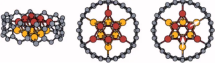
(4) PHYSICAL REVIEW B 73, 125435 共2006兲. WEISSMANN et al.. TABLE III. Interaction energies E, magnetic moments at, and electronic charges q, of Fe encapsulated in R 共n , 0兲 single wall carbon nanotubes. NR indicates nonrelaxed and R relaxed systems. ⌬E = ECNT+Fe NR − ECNT+Fe. The superindices P and I stand for peripheral and interior iron atoms, respectively. The last two rows show the results for free standing iron wires with 6 and 12 atoms per layer, for comparison. Type 共9 , 0兲-6Fe 共10, 0兲-6Fe 共11, 0兲-6Fe 共12, 0兲-6Fe 共13, 0兲-6Fe 共15, 0兲-6Fe 共13, 0兲-12Fe 共15, 0兲-12Fe 6Fe 12Fe. ENR 共eV兲. ER 共eV兲. ⌬E 共eV兲. atP 共B兲. Iat 共B兲. qP. qI. 332.0 115.9 19.4 −1.4 −3.6 −1.9 91.9 −2.4. 13.9 5.6 −3.8 −4.3 −4.6 −2.4 2.4 −6.9. −318.1 −110.3 −23.2 −2.9 −1.0 −0.5 −89.5 −4.5. 0.4 1.9 2.6 2.7 2.9 3.2 −1.1 2.8 3.2 2.9. 1.9 2.2 2.6 2.7 2.7 2.7 2.1 2.6 2.6 2.6. 7.95 7.95 8.00 8.00 7.99 8.01 7.95 7.99 8.05 7.98. 7.98 8.00 8.00 8.00 8.01 7.97 7.98 8.00 7.95 8.02. shown in Fig. 2 using arrows to indicate the displacements of the Fe atoms. For the 共11,0兲 system the relaxed encapsulated structure is attractive, but the unrelaxed one is repulsive. For thinner SWCNT the interaction is repulsive, but relaxation of the structure decreases considerably to this repulsion. We remark that the initial configuration chosen is arbitrary, as the Fe wire may be rotated with respect to the SWCNT which, if the Fe and C atoms are close, may change the interaction energy and even the magnetic configuration. In fact, for the 共9,0兲 case we found two possible relaxed structures depending on the initial configuration. One is stabilized as FM, although the magnetic moments of the Fe atoms close to C are very small, while the other is AP. The general tendency is that the encapsulated nanowires are stable and FM unless the Fe atoms are positioned too close to the carbons, at which point the system becomes unstable and the AP structure may be preferred. In many cases both FM and AP structures could be stabilized as the energy difference between them was small. Thus, one could expect them to coexist at finite temperatures, with the implications for the exchange bias phenomenon5,20,21 we mentioned before. Apart from hcp 共0001兲 encapsulated wires we also computed the energies and magnetic moments of an iron bcc 共110兲 nanowire of 6 Fe atoms per layer, in the FM structure, encapsulated in a 共12,0兲 SWCNT. The magnetic moment is 2.6 B per iron atom. The energy of this system is only 0.1 eV per Fe atom lower than that of the hcp 共0001兲 nanowire with 6 Fe atoms per layer. The AP solution was also found but it has a much larger energy. For the 12-Fe per layer wires we studied only two encapsulated cases, in 共13,0兲 and 共15,0兲 SWCNT; the larger diameter 共15,0兲 case turns out to be stable 共attractive兲, but the 共13,0兲 is weakly repulsive. The unrelaxed and relaxed structures are illustrated in Fig. 3. In the 共13,0兲 SWCNT the optimized geometry of the nanowire is slightly distorted relative to the unrelaxed one 共see the upper panel of Fig. 3兲. The average diameter of the nanotube increases from 10.33 Å to 11.04 Å, and the width of the wire shrinks from 7.37 to 7.26 Å. As far as the magnetism is concerned a striking. change takes effect: we cannot stabilize the FM structure and a special AP ordering appears. The average magnetic moment of the interior iron atoms is opposite to that of the peripheral ones, which amounts to a qualitative reordering of the magnetic structure. The average magnetic moment of the carbon atoms is less than 0.1 B. The magnetic moments and charges of the Fe atoms are shown in Table III. The nanowire encapsulated in the 共15,0兲 SWCNT after relaxation may change its structure from hcp to bcc. Both situations are stable and their energies differ by 1 eV per unit cell, or 0.04 eV per Fe atom, favoring the bcc 共001兲 structure. In that case the initial wire diameter of 7.47 Å stretches to 8.04 Å. FIG. 3. 共Color online兲 Iron hcp 共0001兲 nanowire, with 12 Fe atoms per layer, encapsulated in a carbon nanotube system. The top illustrations correspond to the 共13,0兲 SWCNT, and the bottom ones to the 共15,0兲 nanotube. The unrelaxed configurations are shown on the left and relaxed configurations on the right. The atoms are represented in the same way as in Fig. 2.. 125435-4.
(5) THEORETICAL STUDY OF IRON-FILLED CARBON NANOTUBES. PHYSICAL REVIEW B 73, 125435 共2006兲. FIG. 4. 共Color online兲 Isocurves of the difference between the spin up and the spin down charge densities for one layer of the 12 Fe-atom per layer wire encapsulated in a 共13,0兲 carbon nanotube. The darker color represents a net spin up and the lighter color a net spin down charge. 共a.u.兲 stands for atomic units.. FIG. 5. 共Color online兲 Isocurves of the difference between the spin up and the spin down charge densities for one layer of the 12 Fe-atoms per layer wire encapsulated in a 共15,0兲 carbon nanotube. All the Fe atoms show a net spin up charge. 共a.u.兲 stands for atomic units.. after relaxation and the nanotube also increases its diameter from 11.85 Å to about 12.2 Å. If the structure remains as hcp 共0001兲 the change in the dimensions is much smaller 共7.59 Å and 11.94 Å兲. The isocurves of the spin density distribution for the 12Fe per layer wire encapsulated in 共13,0兲 and 共15,0兲 SWCNT are shown in Figs. 4 and 5, where the darker 共lighter兲 color represent the net spin up 共down兲 charge. As mentioned before, in the more tightly encapsulated 共13,0兲 nanowire the charge densities of the outermost iron atoms polarize opposite to the inner ones. Associated with this polarization is a charge transfer from the Fe to the C atoms as seen in Table III. The average magnetic moment of the innermost iron atoms is 2.1B, while for the outermost it is −1.2 B. The situation is quite different for the wire encapsulated in the 共15,0兲 SWCNT since all the iron atoms are polarized in the same direction, with almost the same charge, and also a negligible charge transfer. For the 共15,0兲 SWCNT all the iron atoms have a magnetic moment of ⬇2.6B. The densities of states of the relaxed structures for the 12-Fe atoms per layer wire encapsulated in 共13,0兲 and 共15,0兲 SWCNT, for the majority and minority bands, are shown in Fig. 6. The density of states at the Fermi level for the 共15,0兲 SWCNT greatly differs for the spin up and the spin down bands. Although zig-zag carbon nanotubes 共n , 0兲 can be semiconductors or metals according to the value of n, those filled with Fe are always metallic. The interesting parameter is the spin polarization of the electrons at the Fermi level. When the diameter of the nanotube is large, the spin polarization is also large, as for the bare nanowires. These systems could be of interest for the use in electron spin injection.. It also is interesting to compare the effect of encapsulating hcp 共0001兲 nanowires 共which are FM when freestanding兲 with hcp 共0001兲 slabs 共which are layered AF when freestanding兲. For this reason we computed the energies and magnetic configurations of a system built as a “sandwich,” with two graphene layers on the “outside” and three iron layers, hcp like ordered 共ABA兲, “inside.” The lowest energy configuration corresponds to the A type iron atoms located on top of the nearest carbon atom of the graphene layer. The magnetic structure of the three iron layers is AP-like, that is up-downup, for stable ABA configurations 共attraction between the iron slab and the graphene layers兲. As we have seen, encapsulated iron nanowires are always FM unless the Fe atoms are very close to the C atoms, in which case AP order may appear. In fact, the case of a 12-Fe per layer wire inside a 共13,0兲 SWCNT is only slightly repulsive, and thus one could expect that thicker wires could be attractive and with concentric layers ordered AP. It had been suggested by Prados et al.5 that inside the CNT there may be a core of bcc iron surrounded by antiferromagnetic fcc iron, which seems similar to this situation. Also, this magnetic structure can be imagined as the “rolling up” of the previous slab along its axis. C. Fe nanowires encapsulated in defective SWCNT. We have also considered nanowires encapsulated in defective SWCNT, hereafter denoted as dCNTs. Our purpose is to explore the structural and magnetic effects of vacancies or vacancy clusters, represented as abundant defects in carbon nanotubes. Also, to analyze the possibility that the inclusion of an excess of inserted iron may break the SWCNT or pre-. 125435-5.
(6) PHYSICAL REVIEW B 73, 125435 共2006兲. WEISSMANN et al.. FIG. 6. Densities of states of wires with 12 Fe atoms per layer, encapsulated in a 共13,0兲 nanotube 共left兲 and in a 共15,0兲 nanotube 共right兲 for the majority 共positive兲 and the minority 共negative兲 spins. Notice the significant difference between majority and minority densities at the Fermi level for the nanowire in the 共15,0兲 nanotube.. vent self-healing. Due to the size of the unit cell used in the present calculations the defects we studied remove a whole row of atoms along the nanotube. Although there is no experimental evidence for this type of defect we believe that the local structure and magnetic moments close to the vacant sites will, in general, be adequately described. Unfortunately not much experimental data on the structure of the most frequent defect is available, and in this respect we mention that large defects have been recently proposed to reconcile the discrepancy between experimental36 and calculated37,38 fracture strengths of unfilled carbon nanotubes. The type of defect studied here is illustrated in Fig. 7 and consists of removing 2 or 3 carbon atoms from the unit cell. The examples we show below remove 3 carbon atoms from the 共11,0兲 SWCNT and 2 carbon atoms from the 共12,0兲 one. To create such a defect in the SWCNT has a large energy cost which can be estimated as EdCNT − ECNT + NCE共C兲, where NC is the number of C atoms that is removed 关3 and 2 for the d共11, 0兲 and d共12, 0兲, respectively兴, and E共C兲 is the energy of the C atom calculated in the same way as for the nanotube and the encapsulated system. The values we obtained are 32.7 eV and 20.5 eV for the d共11, 0兲 and d共12, 0兲, respectively. However, in fullerenes it was observed that C2 molecules, instead of single C atoms, are generated. Thus, it is more realistic to reduce these values by 9.5 eV, the formation energy of C2. For the iron wire encapsulated in a defective nanotube we calculate the interaction energy as E = EdCNT+Fe − EdCNT − ENW. For the 共11,0兲 nanotube the interaction energy is −7.3 eV, while for the 共12,0兲 case it is −5.4 eV. We notice that in both cases this implies that these structures are more favorable than the same iron wire encapsulated in a perfect SWCNT. However, it is not easy to generate this type of defect in a nanotube due to the large energy required. The magnetic moments of the carbon atoms in the bare defective SWCNT are negligible, except for some C atoms on the edge of the nanotube opening where at ⬇ 0.7B, a behavior that is consistent with recent reports.39,40 For the. total magnetic moment of the 共11,0兲 and 共12,0兲 dCNT we obtain 0.8 and 0.0 B per unit cell, respectively. It is worth mentioning that the 共12,0兲 defective SWCNT “heals” the defect upon relaxation, by closing the gap between carbon atoms on opposite edges of the defect. The 共11,0兲 dCNT+ Fe instead remains open along the cut as illustrated in Fig. 7. These results are similar to those of fullerene molecules, that eject C2 molecules and rebond when excited by laser radiation. When these dCNT are filled with an Fe hcp 共0001兲 NW with 6 atoms per layer all the magnetic moments change. For. FIG. 7. 共Color online兲 Iron hcp 共0001兲 nanowire, with 6 atoms per layer, encapsulated in defective carbon 共11,0兲 共upper panel兲 and 共12,0兲 zig-zag 共lower panel兲 nanotubes. The atoms are represented the same way as in Fig. 2. The left 共right兲 illustration corresponds to the unrelaxed 共relaxed兲 case.. 125435-6.
(7) THEORETICAL STUDY OF IRON-FILLED CARBON NANOTUBES. the d共11, 0兲 case the moment of the C atom close to the defect decreases considerably and orders antiparallel to that of the nearest Fe atom, which is also very small, 1.3B. However, the interior Fe atoms have moments of 2.8B. For the d共12, 0兲 case the effect subsists but it is smaller, again the Fe atoms close to the defect have a smaller magnetic moment than the interior ones, 2.2B versus 2.8B. It is interesting to compare this with the previous results for perfect SWCNT, where the magnetic moment of all the Fe atoms was the same. It is clear that defects in the nanotube structure influence the magnetic properties of the composite system. IV. SUMMARY AND CONCLUSIONS. We have examined the properties of iron nanowires encapsulated in SWCNT, through the study of several specific examples. We started considering free standing iron nanowires to precisely determine the changes brought about by the Fe-C interaction. The Fe nanowire geometries we adopted consist of an increasing number of iron atoms per layer, and two layers per unit cell, arranged in hcp 共0001兲 and bcc 共011兲 structures repeated periodically parallel to the wire axis. In all cases the ferromagnetic structure was lower in energy, in spite of the fact that bulk hcp iron and hcp 共0001兲 slabs are antiferromagnetic. Next we computed the variations due to the encapsulation of nanowires with 6 and 12 Fe atoms per layer into zig-zag SWCNT of varying diameter, both with and without defects. In the small diameter SWCNT, where the iron wire fits very tightly, the encapsulated system is unstable and the iron may order AP. In these cases the magnetic moment of the Fe close. Monthioux, Carbon 40, 1809 共2002兲. Svensson, H. Olin, and E. Olsson, Phys. Rev. Lett. 93, 145901 共2004兲. 3 N. Y. Jin-Phillipp and M. Ruhle, Phys. Rev. B 70, 245421 共2004兲. 4 M. Weissmann, G. García, M. Kiwi, and R. Ramírez, Phys. Rev. B 70, 201401共R兲 共2004兲. 5 C. Prados, P. Crespo, J. M. Gonzalez, A. Hernando, J. F. Marco, R. Gancedo, N. Grobert, M. Terrones, R. M. Walton, and H. W. Kroto, Phys. Rev. B 65, 113405 共2002兲. 6 S. Karmakar, S. M. Sharma, M. D. Mukadam, S. M. Yusuf, and A. K. Sood, J. Appl. Phys. 97, 054306 共2005兲. 7 M. S. Ferreira and S. Sanvito, J. Magn. Magn. Mater. 290-291, 286 共2005兲. 8 N. Demoncy, O. Stéphan, N. Brun, C. Colliex, A. Loiseaux, and H. Pascard, Eur. Phys. J. B 4, 147 共1998兲. 9 J. B. Wang, X. Z. Zhou, Q. F. Liu, D. S. Xue, F. S. Li, B. Li, H. P. Kunkel, and G. Williams, Nanotechnology 15, 485 共2004兲. 10 G. Bilalbegović, Vacuum 71, 165 共2003兲. 11 C.-K. Yang, Appl. Phys. Lett. 85, 2923 共2004兲. 12 S. Karmakar, S. M. Sharma, P. V. Teredesai, and A. K. Sood, Phys. Rev. B 69, 165414 共2004兲. 13 T. Muhl, D. Elefant, A. Graff, R. Kozhuharova, A. Leonhardt, I. Monch, M. Ritschel, P. Simon, S. Groudeva-Zotova, and C. M. Schneider, J. Appl. Phys. 93, 7894 共2003兲. 1 M. 2 K.. PHYSICAL REVIEW B 73, 125435 共2006兲. to the C is small and there is a transfer of electrons from Fe to C. As one may expect, the repulsive interaction between the NW and the SWCNT, per Fe atom, is smaller for thicker wires and it may even change sign for the large diameter wires used experimentally. As the diameter of the CNT increases the internal and peripheral magnetic moments tend to equalize, the charge transfer tends to disappear and a binding energy between the wire and CNT appears. The maximum attractive interaction amounts to about 0.3 eV per Fe atom. If the diameter of the SWCNT is large the binding energy decreases, the Fe-C orbital hybridization is small and the magnetism of the system is almost equal to the free standing nanowire, peripheral Fe atoms having larger magnetic moments. Single wall carbon nanotubes with a linear defect were also investigated. While the stability and energetics of the system is only slightly altered, the magnetization of the iron atoms close to the defect are substantially reduced. The fact that the AP and FM arrangements, especially in the case of tight encapsulation, have energies that differ only slightly points to their likely coexistence in real systems at finite temperatures. Thus, this may constitute an explanation for the observation of the exchange bias phenomenon in some systems that has recently been reported.5,6 ACKNOWLEDGMENTS. This work was supported by the Fondo Nacional de Investigaciones Científicas y Tecnológicas 共FONDECYT, Chile兲 under Grants Nos. 1030957 共M.K.兲 and 1040356 共R.R.兲 and by MECESUP 共G.G.兲.. 14 B.. C. Satishkumara, A. Govindaraja, P. V. Vanithaa, A. K. Raychaudhuric, and C. N. R. Rao, Chem. Phys. Lett. 362, 301 共2002兲. 15 C.-K. Yang, J. Zhao, and J. P. Lu, Phys. Rev. Lett. 90, 257203 共2003兲. 16 Y. Yagi, T. M. Briere, M. H. F. Sluiter, V. Kumar, A. A. Farajian, and Y. Kawazoe, Phys. Rev. B 69, 075414 共2004兲. 17 S. B. Fagan, R. Mota, A. J. R. da Silva, and A. Fazzio, Phys. Rev. B 67, 205414 共2003兲. 18 Y.-J. Kang, J. Choi, C.-Y. Moon, and K. J. Chang, Phys. Rev. B 71, 115441 共2005兲. 19 T. Nautiyal, T. H. Rho, and K. S. Kim, Phys. Rev. B 69, 193404 共2004兲. 20 J. Nogués and I. K. Schuller, J. Magn. Magn. Mater. 192, 203 共1999兲. 21 M. Kiwi, J. Magn. Magn. Mater. 234, 584 共2001兲. 22 B. Dieny, V. S. Speriosu, S. Metin, S. S. P. Parkin, B. A. Gurney, P. Baumgart, and D. R. Wilhoit, J. Appl. Phys. 69, 4774 共1991兲. 23 B. Dieny, V. S. Speriosu, S. S. P. Parkin, B. A. Gurney, D. R. Wilhoit, and D. Mauri, Phys. Rev. B 43, R1297 共1991兲. 24 P. Ordejón, E. Artacho, and J. M. Soler, Phys. Rev. B 53, R10441 共1996兲. 25 J. M. Soler, E. Artacho, J. D. Gale, A. García, J. Junquera, P. Ordejón, and D. Sánchez-Portal, J. Phys.: Condens. Matter 14,. 125435-7.
(8) PHYSICAL REVIEW B 73, 125435 共2006兲. WEISSMANN et al. 2745 共2002兲. J. M. Soler, M. R. Beltran, K. Michaelian, I. L. Garzon, P. Ordejón, D. Sánchez-Portal, and E. Artacho, Phys. Rev. B 61, 5771 共2000兲. 27 P. Blaha, K. Schwarz, G. K. H. Madsen, D. Kvasnicka, and J. Luitz, An Augmented Plane Wave ⫹ Local Orbitals Program for Calculating Crystal Properties 共Karlheinz Schwarz, Techn. Universität Wien, Austria, 2001兲, isbn 3-9501031-1-2. 28 J. P. Perdew and A. Zunger, Phys. Rev. B 23, 5048 共1981兲. 29 J. P. Perdew, K. Burke, and M. Ernzerhof, Phys. Rev. Lett. 77, 3865 共1996兲. 30 J. P. Perdew, K. Burke, and M. Ernzerhoff, J. Chem. Phys. 105, 9982 共1996兲. 31 P. Hohenberg and W. Kohn, Phys. Rev. 136, B864 共1964兲. 32 W. Kohn, Rev. Mod. Phys. 71, 1253 共1999兲. 33 C. C. Fu, F. Willaime, and P. Ordejon, Phys. Rev. Lett. 92, 26. 175503 共2004兲. C. Fu, J. D. Torre, F. Willaime, J. L. Bocquet, and A. Barbu, Nat. Mater. 4, 68 共2005兲. 35 R. Saito, G. Dreselhaus, and M. S. Dreselhaus, Physical Properties of Carbon Nanotubes 共Imperial College, London, 1998兲. 36 M.-F. Yu, O. Lourie, M. J. Dyer, K. Moloni, T. F. Kelly, and R. S. Ruoff, Science 287, 637 共2000兲. 37 S. Zhang, S. L. Mielke, R. Khare, D. Troya, R. S. Ruoff, G. C. Schatz, and T. Belytschko, Phys. Rev. B 71, 115403 共2005兲. 38 A. V. Krasheninnikov, K. Nordlund, and J. Keinonen, Phys. Rev. B 65, 165423 共2002兲. 39 Y.-H. Kim, J. Choi, K. J. Chang, and D. Tománek, Phys. Rev. B 68, 125420 共2003兲. 40 P. O. Lehtinen, A. S. Foster, Y. Ma, A. V. Krasheninnikov, and R. M. Nieminen, Phys. Rev. Lett. 93, 187202 共2004兲. 34. 125435-8.
(9)
Figure


+2

Documento similar
The experimental molecules 共blue lines, right兲 and simulated RNAs 共cyan lines, center兲 are drawn together with the secondary structures obtained with the program MFOLD 共left兲,
16 The first general observation we make is that the values increase 共toward more positive EAs兲 with respect to the vertical magnitude, VEA, in accordance to the geometry relaxation
Apart from having conducted an extensive study of the viral life cycle of nonattenuated and attenuated vaccinia virus vectors in primary human macrophages, we performed
The function of inhibition is not just to organize a balance with excitation in order to stabilize a network but much more: 共a兲 inhibitory networks can generate rhythms, such
Wave-function-based ab initio calculations on the lowest states of the 4f n , 4f n−1 5d共t 2g 兲 1 , and 4f n−1 5d共e g 兲 1 configurations of 共LnCl 6 兲 3− clusters 共Ln=Ce
In addition, the size distribution of carbon coated iron nanoparticles is broad by using this method as shown in TEM image (a) and size distribution histogram (b) of Figure
The content of this dissertation comprises the design of two arc-discharge plasma (ADP) reactors (a conventional and a modified one); the experimental study of the different
共Received 29 July 2005; revised manuscript received 18 August 2008; published 10 February 2009 兲 The retrieval abilities of spatially uniform attractor networks can be measured by
