SMS-based optimization strategy for
ultra-compact SWIR telephoto lens design
Wang Lin,1,* Pablo Benítez,1,2 Juan C. Miñano,1,2 José M. Infante,1,3 Guillermo Biot,1 and Marta de la Fuente3
1CEDINT, Universidad Politécnica de Madrid, Spain 2LPI, 2400 Lincoln Avenue, Altadena, California 91001, USA
3Indra Sistemas SA, Spain *
Abstract: A new optical design strategy for rotational aspheres using very few parameters is presented. It consists of using the SMS method to design the aspheres embedded in a system with additional simpler surfaces (such as spheres, parabolas or other conics) and optimizing the free-parameters. Although the SMS surfaces are designed using only meridian rays, skew rays have proven to be well controlled within the optimization. In the end, the SMS surfaces are expanded using Forbes series and then a second optimization process is carried out with these SMS surfaces as a starting point. The method has been applied to a telephoto lens design in the SWIR band, achieving ultra-compact designs with an excellent performance. ©2012 Optical Society of America
OCIS codes: (080.2740) Geometric optical design; (080.3620) Lens system design; (080.4035) Mirror system design.
References and links
1. M. Born and E. Wolf, Principles of Optics (Cambridge University Press, 1999). 2. R. K. Luneburg, Mathematical Theory of Optics (University of California Press, 1964).
3. R. Winston, J. C. Miñano, and P. Benítez, with contributions of N. Shatz, J. Bortz, Nonimaging Optics, (Academic Press Elsevier, 2004), Chap. 8.
4. J. Chaves, Introduction to Nonimaging Optics (CRC Press, 2008).
5. P. Benítez and J. C. Miñano, “Ultrahigh-numerical-aperture imaging concentrator,” J. Opt. Soc. Am. A 14(8), 1988–1997 (1997).
6. J. C. Miñano, P. Benítez, W. Lin, J. Infante, F. Muñoz, and A. Santamaría, “An application of the SMS method for imaging designs,” Opt. Express 17(26), 24036–24044 (2009).
7. J.M.I Herrero, F. Muñoz, P. Benitez, J. C. Miñano, W. Lin, J. Vilaplana, G. Biot, and M. de la Fuente, “Novel fast catadioptric objective with wide field of view,” Proc. SPIE 7787, 778704 (2010).
8. G. W. Forbes, “Shape specification for axially symmetric optical surfaces,” Opt. Express 15(8), 5218–5226 (2007).
9. W. Lin, P. Benítez, J. C. Minano, J. Infante, and G. Biot “Progress in the SMS design method for imaging optics,” Proc. SPIE 8128, 81280F, 81280F-8 (2011).
10. L. Wang, P. Benítez, J. C. Minano, J. Infante, M. de la Fuente, and G. Biot, “Ultracompact SWIR telephoto lens design with SMS method,” Proc. SPIE 8129, 81290I, 81290I-10 (2011).
11. N. Orestes, Stavroudis, The mathematics of geometrical and physical optics (Wiley-VCH, 2006).
12. R. H. Shepard III and S. W. Sparrold, “Material selection for color correction in the short-wave infrared,” Proc. SPIE 7060, 70600E, 70600E-10 (2008).
13. C. Olson, T. Goodman, C. Addiego, and S. Mifsud, “Design and construction of a short-wave infrared 3.3X continuous zoom lens,” Proc. SPIE 7652, 76522A, 76522A-12 (2010).
14. F. Bociort and M. van Turnhout, “Finding new local minima in lens design landscapes by constructing saddle points,” Opt. Eng. 48(6), 063001 (2009).
15. W. Ulrich, “Freeform Surfaces: Hype or handy Design Tool?” Opening presentation at SPIE Optical Systems Design, Marseille (2011).
16. G. W. Forbes, “Robust, efficient computational methods for axially symmetric optical aspheres,” Opt. Express
1. Introduction
In imaging designs, a generalized Cartesian Oval has long been found to be effective in correcting on-axis spherical aberration [1,2]. An asphere can be constructed directly by fulfilling a constant optical path length from an on-axis image point to an on-axis object point. The SMS (Simultaneous Multiple Surface) method is a direct extension to the Cartesian Oval calculation. Given N input one-parameter bundles and N output one-parameter ray-bundles, N aspheres can be constructed directly. The SMS method was developed primarily as a design method in Non-imaging Optics during the 1990s [3,4]. The method was then extended for designing Imaging Optics. The application of the SMS method for imaging optics was first introduced for the design of an ultra-high numerical aperture RX lens made up of two aspheric surfaces [5]. More recently, the extension of up to four aspheres has been developed [6,7].
Classic imaging design methods depend heavily on multi-parametric optimization techniques. For simple optical systems with few parameters, useful solutions can be found in a short time; however when complex optical systems with many un-determined parameters are considered, a local optimizer can be easily trapped by local minimums and fail to make a significant improvement to initial designs. The SMS method provides an effective way of overcoming local minimums. The direct construction of N aspheres helps to reduce dramatically the total number of parameters, thus avoiding the appearance of many undesired local minimums.
We present here a new design strategy for combining the SMS and multi-parameter optimization. It consists of two phases. In Phase I, the SMS method is used to make a monochromatic design of several aspheres embedded in a system with additional simpler surfaces (such as spheres or conics) and the few free parameters are optimized. In Phase II, the SMS surfaces are expanded using the Forbes Q-con polynomial series [8] and a second optimization process is carried out with these SMS polynomials as a starting point. The presentation of this new design strategy is made using a particular design: an ultra-compact telephoto lens configuration for the short-wave infrared (SWIR) band (0.9µm −1.7µm).
This paper is organized as follows. In section 2, the SMS imaging algorithm used in the following sections is described. Its stability has been improved with respect to earlier versions [6]. Section 3 contains the specification for the ultra-compact telephoto lens designs and its selected architecture, called RXXR. In section 4, the results of the Phase I optimization are presented, including a partial description of the landscape of the merit function. Finally, section 5 deals with the results of two examples of the Phase II optimization: a monochromatic design, with the same RXXR architecture, and a polychromatic one, for which an additional lens with a different material has been added to permit the color correction.
2. Improved SMS-3M design algorithm
The SMS method can be implemented to design using meridian and skew ray-bundles. In this work we will used the SMS-3M, in which three meridian ray-bundles are used to design three aspheric surfaces. Although the SMS surfaces are designed using only meridian rays, the skew rays will also be very well controlled within the Phase I optimization process described in Section 4.
guaranteed. The lack of C2 smoothness will finally result either in instabilities of the algorithm or poor final fitting of the curves (represented by NURBS in the SMS calculation process) with overall polynomial aspheres, which is of interest for Phase 2 of the design.
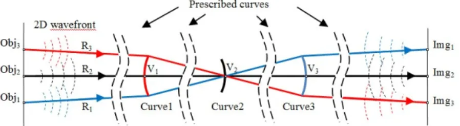
The three meridian ray bundles selected for the SMS design correspond to the rays emitted from 3 object points placed symmetrically about the optical axis, as shown in Fig. 1. V1, V2 and V3 are the central vertices of the initial curves that can be defined beforehand by the designer as a degree of freedom. Consider the rays R1, R2 and R3 shown in Fig. 1, which all pass through the vertex of Curve 2: V2. R2 is the on-axis ray emitted from the on-axis point Obj2 to reach its on-axis image point Img2. R1 is emitted from an off-axis point Obj1 to reach its prescribed off-axis image point Img1 and R3 is its symmetrical counterpart.
Fig. 1. Ray trajectories from the design object points to their corresponding image points used to design the central segments.
The trajectory of R2 from Obj2 to Img2 is guaranteed by normal incidence on all surfaces. The condition that R1 emitted from Obj1 reaches Img1 sets up a relationship between the slopes of Curve 1 and Curve 2 on their rims. Furthermore, the conditions of C2 smoothness at these edge points set up a second constraint on the curvatures of Curve 1 and Curve 2 on their rims. This second constraint is obtained by computing the propagation using a generalized ray-tracing [11] of the meridian curvature of the wave-fronts around R1 and forcing the center of curvature of that wave-front to coincide with Img1. Equation (1) [11] establishes the relationship between the curvature of the incoming wave-front ki along a meridian ray, the
curvature of the outgoing wave-front kr and the curvature of the intersected curve kc. Angles αi
and αr are incident and refracted angles with respect to the normal. A similar law for reflective
surface can be obtained by changing nr to −ni in Eq. (1). Since there are two conditions to be
fulfilled, two degrees of freedom are needed, which means that Curves 1 and 3 can be represented, for instance, as spheres, the two radii being calculated with these conditions. The solution is in general not unique. Different solutions usually represent initial curves with concave or convex shapes, which lead to different families of optical designs.
2 2
cos cos ( cos cos )
i i i r r r i i r r c
n k α −n k α = n α −n α k (1) Once these central segments are selected, the second step for progressing from them to the rim of the full aperture lenses is carried out using the Generalized Cartesian Oval method described elsewhere [6].
3. Tele-photo design specifications and the RXXR architecture
A particular example of application has being selected: a telephoto camera to be mounted on a gimbal in a UAV surveillance system. The difficulty of this design is maintaining a high performance a with small overall system length, which is very important in such a space-limited application. The design of an ultra-compact telephoto lens requires highly non-paraxial architectures. Since it is an unconventional problem, we do not know of a similar design to start with, and thus the SMS is suitable to be applied, since it does not require any previous information.
However, comparing it to the visible band, the SWIR band is almost twice as long, and the optical properties of a lot of common glass have changed significantly, which makes the glass selection very different from ordinary visible-band designs [12,13]. Particularly, glass properties like Abbe value are generally different from those in the visible band, and the number of possible crown-flint combinations is also reduced, compared to the visible band [12].
Table 1. Specifications of the Telephoto Design
Spectral band Focal Length F# Diagonal field of view Pixel size Optic dimensions
0.9-1.7µm 800mm 8 ±0.590 20µm 100mm*60mm
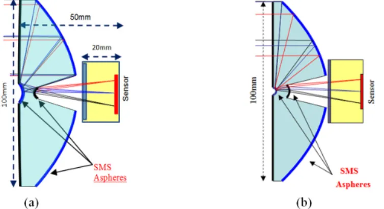
In order to achieve the low depth required, we proposed the “RXXR” architecture, of which two examples are shown in Fig. 2. In the SMS nomenclature: “R” refers to a refractive surface, and “X” refers to a reflective surface; an optical system is named by the surfaces’ optical sequence. In an RXXR, there are 4 surfaces to be designed. The first refractive surface is going to be in the shape of a parabola (shown with a slight curvature in Fig. 2, almost flat) and the other 3 surfaces can then be designed with the SMS-3M method described in Section 2.
Once the central vertices positions are fixed, there are two different unique solutions (shown in Fig. 2), which have different center curvatures. These correspond to the two solutions to the central portion equations described in Section 2. The exit refractive surface in Fig. 2(a) has a concave shape, while in Fig. 2(b) it has a convex shape. If the sign of the focal length is reversed, there are two other families (not shown in Fig. 2) in which the small mirror is convex rather than concave.
Fig. 2. RXXR designs with the same vertice positions and identical front surface with(a) concave exit refractive surface; (b) with convex exit refractive surface.
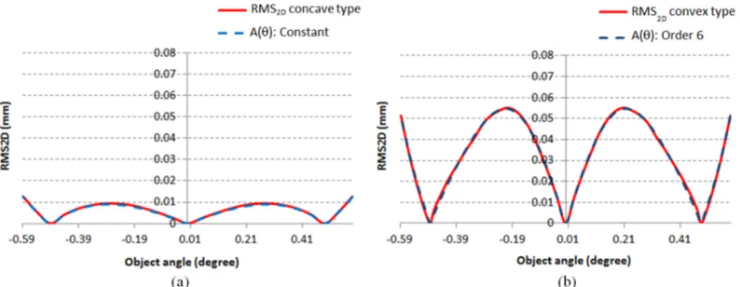
The designed object angles have been selected so that their RMS2D distribution curves (defined as the RMS spot diameter calculated with only meridian rays within the field) present a constant ripple over the field of view. Since the SMS method guarantees that the RMS2D is null at the design object angles, the general form of the function RMS2D(θ) is [6]:
(
2 2)
2D 1
RMS ( )θ = A( )θ θ −θ θ (2)
where θ1 is a designed off-axis object angle and A(θ) is an arbitrary even function. The best
performing SMS designs usually have A(θ) ≈constant [6], for which Eq. (2) is just the
constant A(θ) does not fit well, but a sixth-order approximation is needed (A(θ) =
1.78156−10.5θ2 + 34.5628θ4−36.4749θ6, θ in degrees, A in mm/deg3), as shown in Fig. 3(b). Comparing the maximum RMS2D values for both graphs in Fig. 3, the concave exit surface design has much lower value than the convex one. Therefore the concave exit surface design has a better control over all meridian rays, and thus in the following sections, only the concave exit surface type will be considered.
Fig. 3. RMS diameter of the spot produced by meridian rays only, labeled as RMS2D,for the two designs in Fig. 2: (a) concave exit refractive surface; (b) convex exit refractive surface. The absolute value of the 3rd order best fit polynomial sharing the zeros is also shown.
4. Phase I optimization
Each of the two RXXR solutions in Fig. 2 has 5 free parameters: the position of the 4 vertices on the optical axis which are defined as distance from the image plane, and the on-axis curvature of the parabola. Those parameters can therefore be optimized to minimize a certain merit function, or alternatively some of them can be fixed to guarantee certain geometrical constraints (edge thickness, percentage of obscuration, center thickness, manufacturability, etc). In this optimization, vertices 1, 2, and 3 are limited within a relative small parametric range to keep the lens compact, while vertex 4 can vary in a bigger range.
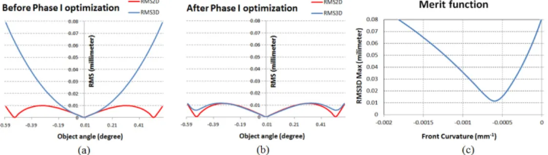
Since the design is monochromatic, we have used an artificial material with a refractive index of 1.5. Then we optimized those 5 free parameters to find a local minimum. The initial curvature of parabola is set to 0 (as a straight line). During each cycle, the other 3 aspheres are calculated using the SMS-3M algorithm. The merit function for this optimization is to minimize the largest RMS3D spot size within the field (calculated by 3D ray-tracing over the whole pupil). We have found that for a fixed set of vertices positions, varying central curvature of frontal parabola can always give a strong reduction to the merit function.
Fig. 4. SMS Phase I optimization of the central curvature of first parabola. (a) before optimization, central curvature = 0mm−1; (b) after optimization, central curvature =
−0.00055mm−1;(c) Merit function.
Up to now, we have fixed the four vertices and varied the curvature of the front parabolic surface only. However, it is interesting to visualize the local landscape of the 5-parameter space around the optimum found.
Fig. 5. Merit functions of vertices position optimization.
Figure 5 shows the cross-section of the merit function when varying only one of the 4 remaining parameters: the four vertex positions. The merit function varies smoothly within the explored parameter space. Vertices 1, 2 and 3 only exhibit one local minimum. Vertex 4 shows two local minima in its coordinate section, one of which around 30mm has been successfully overcome by the optimizer to find a better minimum. These variations of RMS3D (on Fig. 5) in the range explored are small compared to the variation given by the front central curvature (on Fig. 4(c)), as it is common to find in conventional multi-parameter optimization of the spherical optics [14].
5. Phase II optimization
In this expansion, Q-con type polynomials will be used [8], although better optimization results have been recently reported with Q-bfs polynomials [15,16].
5.1. Further optimization of the monochromatic design
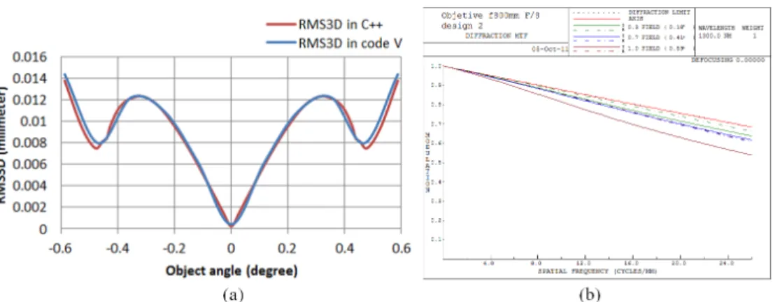
Fig. 6. Monochromatic design in Code V before optimization. (a) Comparison of RMS3D in C + + and Code V; (b) MTF performance before optimization.
In order to verify that the Q-con polynomial representation in Code V is a good approximation of the surfaces that we calculated with the SMS method, we compare their RMS3D distributions, as shown in Fig. 6(a). The two RMS3D curves are very well matched. Three designed object angles can be seen to correspond to 3 local minimum RMS3D values. In Fig. 6(b), the MTF performance for all fields of view is very close to the diffraction limit at 1,300 nm. However, further improvement for this monochromatic design is still possible, because the RMS3D distribution curve is not well balanced between the central field and the edge field.
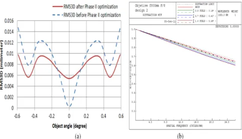
Fig. 7. Monochromatic design in code V after optimization: (a) RMS3D distribution; (b) Optimized MTF.
5.2. Polychromatic design
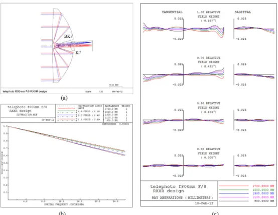
The SMS monochromatic design from the Phase I optimization can be also taken as a starting point for further full-band optimization (900-1,700 nm) with real materials, adding a lens (initially a flat one) at the exit of the RXXR. Figure 8 shows the optimization results with an overall system length of less than 60mm. The front surface of the small lens is an asphere and the back surface is a sphere. Again, during the optimization all aspheres are represented by polynomials with orders of less than 10 degrees. Further reduction to the number of the aspheres’ coefficients is still possible. The final system distortion is less than 1% and obscuration caused by central small mirror surface is less than 5%. This simple final configuration demonstrates that a good starting point cannot only make the design process more efficient, but also reduces the complexity of optical systems.
Fig. 8. RXXR achromatic design in Code V: (a) BK7 (flint) and k7 (crown) combination is used to correct chromatic aberrations; (b) MTF value is very close to the diffraction limit; (c) Ray aberrations remain small for all field angles.
6. Conclusion
In this work, we have presented an SMS-based optimization strategy, which consists of two design phases. In the first phase, the optical system is considered as monochromatic. The SMS method, which does not restrict the surface asphericty or system paraxiality, is embedded in an optimization process of the free parameters (vertex positions, etc), so that the SMS procedure is repeated in every iteration. In the second phase, the SMS monochromatic design is used as a starting point for further monochromatic or polychromatic optimization in commercial optical software.
We have applied this design strategy to an ultra-compact SWIR camera design. In order to achieve ultra-compactness, an optical architecture RXXR is proposed, which can fold the light in the small overall system length. In the monochromatic design, the SMS construction method is implemented with a prescribed parabolic front surface. Two sets of central curvatures (concave and convex) are then found as solutions to the C2 smoothness condition. A comparison between these two types of solutions reveals that the concave structure has a better performance than the convex type.
Acknowledgement