PRUEBA DE HABILIDADES PRACTICAS CISCO CCNP
PRESENTADO POR: YEBIR ALDAIR ORTIZ
GRUPO: 208014_9
PRESENTADO A:
ING. GERARDO GRANADOS ACUÑA
UNIVERSIDAD NACIONAL ABIERTA Y A DISTANCIA UNAD
TABLA DE CONTENIDO
INTRODUCCIÓN ... 3
DESARROLLO DE LA ACTIVIDAD ... 4
Escenario 1 ... 4
Escenario 2 ... 16
Escenario 3 ... 24
CONCLUSIONES ... 42
INTRODUCCIÓN
Las redes de telecomunicaciones en la actualidad juegan un papel muy importante ya que han revolucionado el comercio en el mundo y prestado al hombre una mejor vida cotidiana a la hora de hacer negocios y comunicarse con sus seres queridos en cualquier parte del mundo y transportar información en cuestión de segundos a grandes distancias.
DESARROLLO DE LA ACTIVIDAD
Descripción de escenarios propuestos para la prueba de habilidades
Escenario 1
1. Aplique las configuraciones iniciales y los protocolos de enrutamiento para los routers R1, R2, R3, R4 y R5 según el diagrama. No asigne passwords en los routers. Configurar las interfaces con las direcciones que se muestran en la topología de red.
Procedemos a hacer las configuraciones iniciales en cada uno de los router. Configuración R1
Código:
Router>enable Router#configure t
Enter configuration commands, one per line. End with CNTL/Z. Router(config)#hostname R1
R1(config)#interface serial 0/0
R1(config-if)#ip address 10.103.12.1 255.255.255.252 R1(config-if)#no sh
%LINK-5-CHANGED: Interface Serial0/0, changed state to down R1(config-if)#cl
R1(config-if)#clock rate 12500 Unknown clock rate
R1(config-if)#clock rate 125000 R1(config-if)#exit
R1(config)#exit R1#
Configuración R2 Código:
Router>enable Router#configure t
Enter configuration commands, one per line. End with CNTL/Z. Router(config)#hostname R2
R2(config)#interface serial 0/0
R2(config-if)#ip address 10.103.12.2 255.255.255.252 R2(config-if)#no sh
R2(config-if)#
%LINK-5-CHANGED: Interface Serial0/0, changed state to up R2(config-if)#
R2#configure t
Enter configuration commands, one per line. End with CNTL/Z. R2(config)#interface serial 0/1
R2(config-if)#ip address 10.103.23.1 255.255.255.252 R2(config-if)#no sh
%LINK-5-CHANGED: Interface Serial0/1, changed state to down R2(config-if)#clock rate 125000
R2(config-if)#exit R2(config)#exit R2#
%LINEPROTO-5-UPDOWN: Line protocol on Interface Serial0/0, changed state to up
R2#
%SYS-5-CONFIG_I: Configured from console by console
Router>enable Router#configure t
Enter configuration commands, one per line. End with CNTL/Z. Router(config)#hostname R3
R3(config)#interface serial 0/1
R3(config-if)#ip address 10.103.23.1 255.255.255.0 R3(config-if)#shutdown
R3(config-if)# R3#configure t
Enter configuration commands, one per line. End with CNTL/Z. R3(config)#interface serial 0/1
R3(config-if)#ip address 172.29.34.1 255.255.255.0 R3(config-if)#sh
R3(config-if)#shutdown R3(config-if)#no shutdown
%LINK-5-CHANGED: Interface Serial0/1, changed state to down R3(config-if)#clock rate 125000
R3(config-if)#exit R3(config)#
Código:
Router>enable Router#configure t
Enter configuration commands, one per line. End with CNTL/Z. Router(config)#hostname R4
R4(config)#interface serial 0/0
R4(config-if)#ip address 172.29.34.2 255.255.255.0 R4(config-if)#no sh
R4(config-if)#no shutdown R4(config-if)#
%LINK-5-CHANGED: Interface Serial0/0, changed state to up R4(config-if)#
%LINEPROTO-5-UPDOWN: Line protocol on Interface Serial0/0, changed state to up
R4(config-if)#exit
R4(config)#interface serial 0/1
R4(config-if)#ip address 172.29.45.1 255.255.255.0 R4(config-if)#no sh
R4(config-if)#no shutdown
%LINK-5-CHANGED: Interface Serial0/1, changed state to down R4(config-if)#clock rate 125000
Configuración R5 Código:
Router>enable Router#configure t
Enter configuration commands, one per line. End with CNTL/Z. Router(config)#hostname R5
R5(config)#interface serial 0/0
R5(config-if)#ip address 172.29.45.2 255.255.255.0 R5(config-if)#no sh
R5(config-if)#no shutdown R5(config-if)#
%LINK-5-CHANGED: Interface Serial0/0, changed state to up R5(config-if)#exit
R5(config)#
%LINEPROTO-5-UPDOWN: Line protocol on Interface Serial0/0, changed state to up
Ahora procedemos a agregar el protocolo OSPF área 0
Código R1: R1#configure t
R1(config)#router ospf 1 R1(config-router)#ne R1(config-router)#net
R1(config-router)#network 10.103.12.0 0.0.0.255 area 0 R1(config-router)#end
Código R2: R2#configure t
Enter configuration commands, one per line. End with CNTL/Z. R2(config)#router ospf 1
R2(config-router)#network 10.103.12.0 0.0.0.255 area 0 R2(config-router)#network 10.103.23.0 0.0.0.255 area 0 R2(config-router)#
R2#
Código R3 R3>enable R3#configure t
Enter configuration commands, one per line. End with CNTL/Z. R3(config)#router e
R3(config)#router eigrp 10 R3(config-router)#exit R3(config)#router ospf 1 R3(config-router)#net
R3(config-router)#network 10.103.23.0 0.0.0.255 area 0 R3(config-router)#end
R3#
Configuración protocolo EIGRP Código R4
R4>enable R4#configure t
Enter configuration commands, one per line. End with CNTL/Z. R4(config)#router e
R5>enable R5#configure t
Enter configuration commands, one per line. End with CNTL/Z. R5(config)#router e
R5(config)#router eigrp 10 R5(config-router)#net
R5(config-router)#network 172.29.45.0 R5(config-router)#
%DUAL-5-NBRCHANGE: IP-EIGRP 10: Neighbor 172.29.45.1 (Serial0/0) is up: new adjacency
R5(config-router)#exit R5(config)#
Ahora compartimos las rutas estáticas para que haya conectividad entre los dos protocolos de la siguiente manera:
Primero configuramos en R3 R3>enable
R3#configure t
Enter configuration commands, one per line. End with CNTL/Z. R3(config)#ip route 0.0.0.0 0.0.0.0 serial 0/1
R3(config)#router ospf 1 R3(config-router)#r R3(config-router)#re R3(config-router)#de R3(config-router)#default-information o R3(config-router)#default-information originate R3(config-router)#do wr
Luego en R4 R4>enable R4#configure t
Enter configuration commands, one per line. End with CNTL/Z. R4(config)#ip route 0.0.0.0 0.0.0.0 serial 0/0
R4(config)#router e
R4(config)#router eigrp 10 R4(config-router)#re
R4(config-router)#redistribute s R4(config-router)#redistribute static R4(config-router)#end
R4#
R4#copy running-config startup-config Destination filename [startup-config]? Building configuration...
2. Cree cuatro nuevas interfaces de Loopback en R1 utilizando la asignación de direcciones 10.1.0.0/22 y configure esas interfaces para participar en el área 0 de OSPF.
Creamos las interfaces loopback y las agregamos al OSPF área 0 Código:
R1(config-if)#ip address 10.1.0.1 255.255.255.0 R1(config-if)#ip ospf net
R1(config-if)#ip ospf network poi
R1(config-if)#ip ospf network point-to-point R1(config-if)#exit
R1(config)#interface loopback 1 R1(config-if)#
%LINK-5-CHANGED: Interface Loopback1, changed state to up
%LINEPROTO-5-UPDOWN: Line protocol on Interface Loopback1, changed state to up
R1(config-if)#ip address 10.1.0.2 255.255.255.0 R1(config-if)#ip ospf network point-to-point R1(config-if)#exit
R1(config-if)#ip address 10.1.0.3 255.255.255.0 % 10.1.0.0 overlaps with Loopback0
R1(config-if)#ip ospf network point-to-point R1(config-if)#exit
R1(config)#interface loopback 3 R1(config-if)#
%LINK-5-CHANGED: Interface Loopback3, changed state to up
%LINEPROTO-5-UPDOWN: Line protocol on Interface Loopback3, changed state to up
R1(config-if)#ip address 10.1.0.4 255.255.255.0 R1(config-if)#ip ospf network point-to-point R1(config-if)#exit
R1(config)#
Procedemos a agregar las interfaces loopback y agregarla al eigrp Código
R5>enable R5# enable R5#configure t
Enter configuration commands, one per line. End with CNTL/Z. R5(config)#interface l
R5(config)#interface loopback 0 R5(config-if)#
%LINK-5-CHANGED: Interface Loopback0, changed state to up
%LINEPROTO-5-UPDOWN: Line protocol on Interface Loopback0, changed state to up
R5(config-if)#ip adrress 172.2.5.0.0 255.255.255.0 R5(config-if)#ip address 172.2.5.0.0 255.255.255.0 R5(config-if)#ip address 172.2.5.0 255.255.255.0 Bad mask /24 for address 172.2.5.0
R5(config)#interface loopback 2 R5(config-if)#
%LINK-5-CHANGED: Interface Loopback2, changed state to up
%LINEPROTO-5-UPDOWN: Line protocol on Interface Loopback2, changed state to up
R5(config-if)#ip address 172.2.5.2 255.255.255.0 % 172.2.5.0 overlaps with Loopback1
R5(config-if)#exit
R5(config)#interface loopback 3 R5(config-if)#
%LINK-5-CHANGED: Interface Loopback3, changed state to up
%LINEPROTO-5-UPDOWN: Line protocol on Interface Loopback3, changed state to up
R5(config-if)#ip address 172.2.5.3 255.255.255.0 % 172.2.5.0 overlaps with Loopback1
R5(config-if)#
Ahora vamos a ejecutar el comando en R3 y mirar la tabla que nos arroja
5. Configure R3 para redistribuir las rutas EIGRP en OSPF usando el costo de 50000 y luego redistribuya las rutas OSPF en EIGRP usando un ancho de banda T1 y 20,000 microsegundos de retardo.
Ejecutamos el siguiente código para configurar la redistribución de eigrp en ospf R3(config-router)#exit
R3(config)#router eigrp 10
R3(config-router)#redistribute ospf m R3(config-router)#redistribute ospf me
R3(config-router)#redistribute ospf 1 metric 20000 10 255 255 1500 R3(config-router)#end
R3#
%SYS-5-CONFIG_I: Configured from console by console R3#copy running-config startup-config
Destination filename [startup-config]? Building configuration...
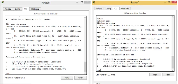
6. Verifique en R1 y R5 que las rutas del sistema autónomo opuesto existen en su tabla de enrutamiento mediante el comando show ip route.
Tabla de enrutamiento R1
Escenario 2
Configuramos los parámetros iniciales de la red.
Código
Router>enable Router#configure t
Enter configuration commands, one per line. End with CNTL/Z. Router(config)#hostname R1
R1(config)#interface serial 0/0
R1(config-if)#ip addres 192.1.12.1 255.255.255.0 R1(config-if)#no shutdown
%LINK-5-CHANGED: Interface Serial0/0, changed state to down R1(config-if)#cl
R1(config-if)#clock rate 12500 Unknown clock rate
R1(config-if)#
R1#enable R1#configure t
Enter configuration commands, one per line. End with CNTL/Z. R1(config)#interface l
R1(config)#interface loopback 0 R1(config-if)#
%LINK-5-CHANGED: Interface Loopback0, changed state to up
%LINEPROTO-5-UPDOWN: Line protocol on Interface Loopback0, changed state to up
R1(config-if)#ip address 1.1.1.1 255.0.0.0 R1(config-if)#exit
R1(config)#interface loopback 1 R1(config-if)#
%LINK-5-CHANGED: Interface Loopback1, changed state to up
%LINEPROTO-5-UPDOWN: Line protocol on Interface Loopback1, changed state to up
R1(config-if)#ip address 11.1.0.1 255.255.0.0 R1(config-if)#exit
Código
Router>enable Router#configure t
Enter configuration commands, one per line. End with CNTL/Z. Router(config)#hostname R2
R2(config)#interface s
R2(config)#interface serial 0/0
R2(config-if)#ip address 192.1.12.2 255.255.255.0 R2(config-if)#exit
R2(config)#interface f
R2(config)#interface fastEthernet 0/0
R2(config-if)#ip address 192.1.23.2 255.255.255.0 R2(config-if)#no sh
R2(config-if)#no shutdown R2(config-if)#
%LINK-5-CHANGED: Interface FastEthernet0/0, changed state to up R2(config-if)#exit
R2(config)#interface l
R2(config)#interface loopback 0 R2(config-if)#
%LINK-5-CHANGED: Interface Loopback0, changed state to up
%LINEPROTO-5-UPDOWN: Line protocol on Interface Loopback0, changed state to up
R2(config-if)#ip address 2.2.2.2 255.0.0.0 R2(config-if)#exit
R2(config)#interface loopback 1 R2(config-if)#
%LINK-5-CHANGED: Interface Loopback1, changed state to up
%LINEPROTO-5-UPDOWN: Line protocol on Interface Loopback1, changed state to up
ip address 12.2.2.2 255.0.0.0
R2(config-if)#ip address 12.1.0.1 255.255.0.0 R2(config-if)#exit
Código
Router>enable Router#configure t
Enter configuration commands, one per line. End with CNTL/Z. Router(config)#hostname R3
R3(config)#interface serial 0/0
R3(config-if)#ip address 192.1.34.3 255.255.255.0 R3(config-if)#no sh
R3(config-if)#no shutdown
%LINK-5-CHANGED: Interface Serial0/0, changed state to down R3(config-if)#
R3(config-if)#exit R3(config)#intef R3(config)#interface f
R3(config)#interface fastEthernet 0/0
R3(config-if)#ip address 192.1.23.3 255.255.255.0 R3(config-if)#no sh
R3(config-if)#no shutdown R3(config-if)#
R3(config-if)#exit R3(config)#interface l
R3(config)#interface loopback 0 R3(config-if)#
%LINK-5-CHANGED: Interface Loopback0, changed state to up
LINEPROTO-5-UPDOWN: Line protocol on Interface Loopback0, changed state to up
R3(config-if)#ip address 3.3.3.3 255.0.0.0 R3(config-if)#exit
R3(config)#interface loopback 1 R3(config-if)#
%LINK-5-CHANGED: Interface Loopback1, changed state to up
%LINEPROTO-5-UPDOWN: Line protocol on Interface Loopback1, changed state to up
R3(config-if)#ip address 13.1.0.1 255.0.0.0 R3(config-if)#exit
R3(config)#end R3#
%SYS-5-CONFIG_I: Configured from console by console R3#copy running-config startup-config
Destination filename [startup-config]? Building configuration...
[OK]
Código
Router>enable Router#configure t
Enter configuration commands, one per line. End with CNTL/Z. Router(config)#hostname R3
R3(config)#hostname R4 R4(config)#interface seria 0/0
R4(config-if)#ip addres 192.1.34.4 255.255.255.0 R4(config-if)#no sh
R4(config-if)#
%LINEPROTO-5-UPDOWN: Line protocol on Interface Serial0/0, changed state to up
R4(config)#interface loo
R4(config)#interface loopback 0 R4(config-if)#
%LINK-5-CHANGED: Interface Loopback0, changed state to up
%LINEPROTO-5-UPDOWN: Line protocol on Interface Loopback0, changed state to up
R4(config-if)#ip addres 4.4.4.4 255.0.0.0 R4(config-if)#exit
R4(config)#interface loopback 1 R4(config-if)#
%LINK-5-CHANGED: Interface Loopback1, changed state to up
%LINEPROTO-5-UPDOWN: Line protocol on Interface Loopback1, changed state to up
R4(config-if)#ip addres 14.1.0.1 255.255.0.0 R4(config-if)#exit
R4(config)#end R4#
%SYS-5-CONFIG_I: Configured from console by console R4#copy running-config startup-config
Destination filename [startup-config]? Building configuration...
[OK] R4#
1. Configure una relación de vecino BGP entre R1 y R2. R1 debe estar en AS1 y R2 debe estar en AS2. Anuncie las direcciones de Loopback en BGP.
Codifique los ID para los routers BGP como 11.11.11.11 para R1 y como 22.22.22.22 para R2. Presente el paso a con los comandos utilizados y la salida del comando show ip route.
Configuramos el BGP en los router R1 y R2 para que sean adyacentes. Código R1
R1#enable R1#configure t
Enter configuration commands, one per line. End with CNTL/Z. R1(config)#no ro
R1(config-router)#neighbor 192.1.12.2 re
R1(config-router)#neighbor 192.1.12.2 remote-as 22
R1(config-router)#%BGP-5-ADJCHANGE: neighbor 192.1.12.2 Up exit
Código R2 R2>enable R2#configure t
Enter configuration commands, one per line. End with CNTL/Z. R2(config)#no ro
R2(config)#no router bgp 7675 R2(config)#ro
R2(config)#router bgp 22 R2(config-router)#nei
R2(config-router)#neighbor 192.1.12.1 re
R2(config-router)#neighbor 192.1.12.1 remote-as % Incomplete command.
R2(config-router)#neighbor 192.1.12.1 remote-as 11 R2(config-router)#
Tabla de direccionamiento con el comando show ip route
2. Configure una relación de vecino BGP entre R2 y R3. R2 ya debería estar configurado en AS2 y R3 debería estar en AS3. Anuncie las direcciones de Loopback de R3 en BGP. Codifique el ID del router R3 como 33.33.33.33. Presente el paso a con los comandos utilizados y la salida del comando show ip route.
Código R3>enable R3#configure t
Enter configuration commands, one per line. End with CNTL/Z. R3(config)#no ro
R3(config)#no router bgp 7675 R3(config)#router bgp 33 R3(config-router)#nei
R3(config-router)#neighbor 192.1.12.2 re
R3(config-router)#neighbor 192.1.12.2 remote-as 22 R3(config-router)#
%LINEPROTO-5-UPDOWN: Line protocol on Interface FastEthernet0/0, changed state to up
R3(config-router)#exit
R3(config)#no router bgp 7675 R3(config)#router bgp 33
R3(config-router)#neighbor 192.1.23.2 remote-as 22 R3(config-router)#end
R3#
Verificamos con el comando show ip route
Establezca las relaciones de vecino con base en las direcciones de Loopback 0. Cree rutas estáticas para alcanzar la Loopback 0 del otro router. No anuncie la Loopback 0 en BGP. Anuncie la red Loopback de R4 en BGP. Presente el paso a con los comandos utilizados y la salida del comando show ip route.
Ahora procedemos a configurar en R4 y R3 el bgp Código
R4>enable R4#configure t
Enter configuration commands, one per line. End with CNTL/Z. R4(config)#no router bgp 7675
R4(config)#router bgp 44 R4(config-router)#nei
R4(config-router)#neighbor 192.1.34.3 re
R4(config-router)#neighbor 192.1.34.3 remote-as 33 R4(config-router)#exit
R4(config)#end R4#
%SYS-5-CONFIG_I: Configured from console by console R4#copy running-config startup-config
Destination filename [startup-config]? Building configuration...
[OK] R4#
R3#enable R3#configure t
Enter configuration commands, one per line. End with CNTL/Z. R3(config)#router bgp 33
R3(config-router)#nei
R3(config-router)#neighbor 192.1.34.4 re
R3(config-router)#neighbor 192.1.34.4 remote-as 44
A. Configurar VTP
1. Todos los switches se configurarán para usar VTP para las actualizaciones de VLAN. El switch SWT2 se configurará como el servidor. Los switches SWT1 y SWT3 se configurarán como clientes. Los switches estarán en el dominio VPT llamado CCNP y usando la contraseña cisco.
Partiendo de la siguiente topología iniciamos la configuración vtp en los switches
Configuración vtp swt2 servidor Código:
SWT2#enable SWT2#configure t
Enter configuration commands, one per line. End with CNTL/Z. SWT2(config)#vtp domain CCNP
Changing VTP domain name from NULL to CCNP SWT2(config)#vtp pas
SWT2(config)#vtp password cisco
Setting device VLAN database password to cisco SWT2(config)#end
SWT2#
%SYS-5-CONFIG_I: Configured from console by console SWT2#copy running-config startup-config
Destination filename [startup-config]? Building configuration...
SWT2#
Configuración vtp swt1 cliente Código:
Switch>enable Switch#configure t
Enter configuration commands, one per line. End with CNTL/Z. Switch(config)#hostname SWT1
SWT1(config)#inter
SWT1(config)#interface fas
SWT1(config)#interface fastEthernet 0/1 SWT1(config-if)#sw
SWT1(config-if)#switchport mode tr SWT1(config-if)#switchport mode trunk SWT1(config-if)#
%LINEPROTO-5-UPDOWN: Line protocol on Interface FastEthernet0/1, changed state to down
%LINEPROTO-5-UPDOWN: Line protocol on Interface FastEthernet0/1, changed state to up
SWT1(config)#vtp mode client
Setting device to VTP CLIENT mode. SWT1(config)#vtp domain CCNP Domain name already set to CCNP. SWT1(config)#vtp pa
SWT1(config)#vtp password cisco
Setting device VLAN database password to cisco SWT1(config)#exit
SWT1#
%SYS-5-CONFIG_I: Configured from console by console SWT1#
Configuración vtp swt3 cliente WT3(config)#inter
SWT3(config)#interface fa
SWT3(config)#interface fastEthernet 0/2 SWT3(config-if)#sw
SWT3(config-if)#switchport mode tr SWT3(config-if)#switchport mode trunk SWT3(config-if)#
%LINEPROTO-5-UPDOWN: Line protocol on Interface FastEthernet0/2, changed state to down
%LINEPROTO-5-UPDOWN: Line protocol on Interface FastEthernet0/2, changed state to up
Setting device to VTP CLIENT mode. SWT3(config)#vtp domain CCNP Domain name already set to CCNP. SWT3(config)#vtp p
SWT3(config)#vtp password cisco
Setting device VLAN database password to cisco SWT3(config)#exit
SWT3#
%SYS-5-CONFIG_I: Configured from console by console SWT3#copy running-config startup-config
Destination filename [startup-config]? Building configuration...
[OK] SWT3#
2. Verifique las configuraciones mediante el comando show vtp status.
3. Configurar DTP (Dynamic Trunking Protocol)
Configure un enlace troncal ("trunk") dinámico entre SWT1 y SWT2. Debido a que el modo por defecto es dynamic auto, solo un lado del enlace debe
configurarse como dynamic desirable. Configuramos la troncal.
Código:
SWT1(config)#inter
SWT1(config)#interface fas
SWT1(config)#interface fastEthernet 0/1 SWT1(config-if)#sw
SWT1(config-if)#switchport mode tr SWT1(config-if)#switchport mode trunk SWT1(config-if)#
4. Verifique el enlace "trunk" entre SWT1 y SWT2 usando el comando show interfaces trunk.
5. Entre SWT1 y SWT3 configure un enlace "trunk" estático utilizando el comando switchport mode trunk en la interfaz F0/3 de SWT1.
6. WT3(config)#inter
7. SWT3(config)#interface fa
8. SWT3(config)#interface fastEthernet 0/2 9. SWT3(config-if)#sw
10. SWT3(config-if)#switchport mode tr 11. SWT3(config-if)#switchport mode trunk 12. SWT3(config-if)#
13. %LINEPROTO-5-UPDOWN: Line protocol on Interface FastEthernet0/2, changed state to down
6. Configure un enlace "trunk" permanente entre SWT2 y SWT3. 7. WT3(config)#inter
8. SWT3(config)#interface fa
9. SWT3(config)#interface fastEthernet 0/3 10. SWT3(config-if)#sw
11. SWT3(config-if)#switchport mode tr 12. SWT3(config-if)#switchport mode trunk 13. SWT3(config-if)#
14. %LINEPROTO-5-UPDOWN: Line protocol on Interface FastEthernet0/2, changed state to down
C. Agregar VLANs y asignar puertos.
1. En STW1 agregue la VLAN 10. En STW2 agregue las VLANS Compras (10), Mercadeo (20), Planta (30) y Admon (99)
Ahora procedemos a agregar las vlan primero en cada uno de los dispositivos que tenemos.
Código:
SWT2>enable SWT2#configure t
Enter configuration commands, one per line. End with CNTL/Z. SWT2(config)#vlan 10
SWT2(config-vlan)#name compras SWT2(config-vlan)#exit
SWT2(config)#vlan 20
SWT2(config-vlan)#name mercadeo SWT2(config-vlan)#exit
SWT2(config)#vlan 30
SWT2(config-vlan)#name planta SWT2(config-vlan)#exit
SWT2(config)#vlan 99
SWT2(config-vlan)#name admon SWT2(config-vlan)#exit
SWT2(config)#end SWT2#
Destination filename [startup-config]? Building configuration...
[OK] SWT2#
2. Verifique que las VLANs han sido agregadas correctamente.
Para verificar las Vlan usamos el comando show vlan
3. Asocie los puertos a las VLAN y configure las direcciones IP de acuerdo con la siguiente tabla.
Partiendo de la tabla configuramos de la siguiente manera: Código:
SWT2#enable SWT2#configure t
Enter configuration commands, one per line. End with CNTL/Z. SWT2(config)#sw
SWT2(config)#interface f0/10 SWT2(config-if)#sw
SWT2(config-if)#switchport mode access SWT2(config-if)#sw
SWT2(config-if)#switchport access vlan 10 SWT2(config-if)#end
SWT2#
Enter configuration commands, one per line. End with CNTL/Z. SWT2(config)#interface f0/15
SWT2(config-if)#sw
SWT2(config-if)#switchport mode access SWT2(config-if)#sw
SWT2(config-if)#switchport access vlan 20 SWT2(config-if)#end
SWT2#
%SYS-5-CONFIG_I: Configured from console by console SWT2#configure t
Enter configuration commands, one per line. End with CNTL/Z. SWT2(config)#interface f0/20
SWT2(config-if)#sw| SWT2(config-if)#sw
SWT2(config-if)#switchport mode ac SWT2(config-if)#switchport mode access SWT2(config-if)#sw
SWT2(config-if)#switchport ac
SWT2(config-if)#switchport access vlan 30 SWT2(config-if)#end
SWT2#
%SYS-5-CONFIG_I: Configured from console by console SWT2#copy running-config startup-config
Destination filename [startup-config]? Building configuration...
[OK]
SWT2#
Este paso se repite con los demás switches. Configuración ip para los pc compras.
Ip para pc planta.
Este paso se realiza en los demás pcs.
4. Configure el puerto F0/10 en modo de acceso para SWT1, SWT2 y SWT3 y asígnelo a la VLAN 10.
Procedemos a realizar la operación SWT1. Código:
SWT1>enable SWT1#configure t
Enter configuration commands, one per line. End with CNTL/Z. SWT1(config)#interface f0/10
SWT1(config-if)#sw
SWT1(config-if)#switchport mode ac SWT1(config-if)#switchport mode access SWT1(config-if)#sw
SWT1(config-if)#switchport access vlan 10 SWT1(config-if)#end SWT1# Configuración STW2. Código: SWT2>enable SWT2#configure t
Enter configuration commands, one per line. End with CNTL/Z. SWT2(config)#interface f0/10
SWT2(config-if)#sw
SWT2(config-if)#switchport mode ac SWT2(config-if)#switchport mode access SWT2(config-if)#sw
SWT2(config-if)#switchport ac
SWT2(config-if)#switchport access vlan 10 SWT2(config-if)#end
SWT2#
%SYS-5-CONFIG_I: Configured from console by console SWT2#
Configuración STW3.
SWT3>enable SWT3#configure t
Enter configuration commands, one per line. End with CNTL/Z. SWT3(config)#interface f0/10
SWT3(config-if)#sw
SWT3(config-if)#switchport mode ac SWT3(config-if)#switchport mode access SWT3(config-if)#sw
SWT3(config-if)#switchport ac
SWT3(config-if)#switchport access vlan 10 SWT3(config-if)#exit
SWT3(config)# SWT3#
%SYS-
5. Repita el procedimiento para los puertos F0/15 y F0/20 en SWT1, SWT2 y SWT3. Asigne las VLANs y las direcciones IP de los PCs de acuerdo con la tabla de arriba.
SWT3#configure te
Enter configuration commands, one per line. End with CNTL/Z. SWT3(config)#interface f0/15
SWT3(config-if)#switchport mode access SWT3(config-if)#switchport access vlan 20 SWT3(config-if)#end
SWT3#
%SYS-5-CONFIG_I: Configured from console by console SWT3#configure te
Enter configuration commands, one per line. End with CNTL/Z. SWT3(config)#interface f0/20
SWT3(config-if)#switchport mode access SWT3(config-if)#switchport access vlan 20 SWT3(config-if)#end
SWT3#
%SYS-5-CONFIG_I: Configured from console by console SWT3#
SWT3#
D. Configurar las direcciones IP en los Switches.
1. En cada uno de los Switches asigne una dirección IP al SVI (Switch Virtual Interface) para VLAN 99 de acuerdo con la siguiente tabla de direccionamiento y active la interfaz.
Partiendo de la tabla de direccionamiento procedemos a realizar este pasó de la siguiente manera:
Configuración SWT1. Código:
SWT1>enable SWT1#configure t
Enter configuration commands, one per line. End with CNTL/Z. SWT1(config)#interface vlan 99
%LINK-5-CHANGED: Interface Vlan99, changed state to up
%LINEPROTO-5-UPDOWN: Line protocol on Interface Vlan99, changed state to up
SWT1(config-if)#ip ad
SWT1(config-if)#ip address 190.108.99.1 255.255.255.0 SWT1(config-if)#exit SWT1(config)#END SWT1# Configuración SWT2. Código: SWT2>enable SWT2#configure t
Enter configuration commands, one per line. End with CNTL/Z. SWT2(config)#interface vlan 99
SWT2(config-if)#
%LINK-5-CHANGED: Interface Vlan99, changed state to up
%LINEPROTO-5-UPDOWN: Line protocol on Interface Vlan99, changed state to up
SWT2(config-if)#ip ad
SWT2(config-if)#ip address 190.108.99.2 255.255.255.0 SWT2(config-if)#exit SWT2(config)# Configuración SWT3 Código: SWT3#enable SWT3#configure t
Enter configuration commands, one per line. End with CNTL/Z. SWT3(config)#interface vlan 99
SWT3(config-if)#
%LINK-5-CHANGED: Interface Vlan99, changed state to up SWT3(config-if)#ip a
SWT3(config-if)#ip address 190.108.99.3 255.255.255.0 SWT3(config-if)#end
SWT3#
E. Verificar la conectividad Extremo a Extremo
1. Ejecute un Ping desde cada PC a los demás. Explique por qué el ping tuvo o no tuvo éxito.
Procedemos a realizar los pings
2. Ejecute un Ping desde cada Switch a los demás. Explique por qué el ping tuvo o no tuvo éxito.
Ping desde swt2 a swt3.
Ping swt1 a swt2.
CONCLUSIONES
Aplique los conocimientos adquiridos en el desarrollo de las diferentes actividades
estudiadas tanto prácticas como teóricas realizadas en el transcurso de nuestro curso de cisco CCNP.
Se Realiza la Simulación de cada una de las redes propuestas en los 3 escenarios
de la guía en pakect Tracer realizando la configuración adecuada para cada caso p escenario propuesto.
.
REFERENCIAS BIBLIOGRÁFICAS
(2015)., U. ((2015).). Switch CISCO Security Management. Obtenido de https://1drv.ms/u/s!AmIJYei-NT1IlyVeVJCCezJ2QE5c
Teare, D. V. ( (2015). ). Implementing a Border Gateway Protocol (BGP) Solution for
ISP Connectivity. Obtenido de
https://1drv.ms/b/s!AmIJYei-NT1IlnMfy2rhPZHwEoWx
Teare, D. V. ( (2015).). Path Control Implementation. Obtenido de https://1drv.ms/b/s!AmIJYei-NT1IlnMfy2rhPZHwEoWx
Teare, D. V. (2015). Implementing Routing Facilities for Branch Offices and Mobile
Workers. . Obtenido de
https://1drv.ms/b/s!AmIJYei-NT1IlnMfy2rhPZHwEoWx
Unad. (s.f.). Principios de Enrutamiento. Obtenido de https://1drv.ms/u/s!AmIJYei-NT1IhgOyjWeh6timi_Tm
Amberg, E. ((2014). ). CCNA 1 Powertraining :. Obtenido de http://bibliotecavirtual.unad.edu.co:2051/login.aspx?direct=true&db=e000xw w&AN=979032&lang=es&site=ehost-live
Froom, R. F. (s.f.). Switching Features and Technologies. Implementing Cisco IP
Switched Networks. Obtenido de
https://1drv.ms/b/s!AmIJYei-NT1IlnWR0hoMxgBNv1CJ