EVALUACION PRUEBAS DE HABILIDADES PRACTICAS CCNA
VIVIANA RINCON PARDO
UNIVERSIDAD NACIONAL ABIERTA Y A DISTANCIA
ESCUELA DE CIENCIAS BASICAS, TECNOLOGIA E EINGENIERIA, ECBTI PROGRAMA DE INGENIERIA DE SISTEMAS
2
EVALUACION PRUEBAS DE HABILIDADES PRACTICAS CCNA
VIVIANA RINCON PARDO
NANCY AMPARO GUACA TUTORA
UNIVERSIDAD NACIONAL ABIERTA Y A DISTANCIA
ESCUELA DE CIENCIAS BASICAS, TECNOLOGIA E EINGENIERIA, ECBTI PROGRAMA DE INGENIERIA DE SISTEMAS
3
CONTENIDO
Pág.
RESUMEN 6
INTRODUCCION 7
OBJETIVOS 8
OBJETIVO GENERAL 8
OBJETIVOS ESPECÍFICOS 8
ESCENARIO 1 9
DISPOSITIVOS 11
DESCRIPCION DE EL ESCENARIO 1. 11
Mostrar con comando show vlan 13
ESCENARIO 2 29
DISPOSITIVOS 30
Configurar el protocolo de enrutamiento OSPFv2 bajo los siguientes criterios: 35
CONCLUSIONES 43
4
LISTA DE TABLAS
Pág.
Tabla No 1. Tabla de direccionamiento 9
Tabla No 2 De Asignación de VLAN y de Puertos 10
Tabla No 3. De Enlaces Troncales 10
5
LISTA DE IMAGENES
Pág.
Imagen No 1 Topología de Red 9
Imagen No 2. Comando show Vlan 13
Imagen No 3. Mostrar Vlan 15
Imagen No 4. Show ip interface brief 18
Imagen No 5. Configuracion NAT OUTSIDE 19
Imagen No 6. Ruta Estática Predeterminada al ISP 19
Imagen No 7. Interfaces Configuradas 20
Imagen No 8. Configuración de ROUTER 3 21
Imagen No 9. Configuración de ROUTER ISP 22
Imagen No 10. Configuracion de Pc 22
Imagen No 11. Show ip Nat Translation 24
Imagen No 12. Show ip Nat Statistics 24
Imagen No 13. Configuración de Servidor 25
Imagen No 14. Configuración de Router 1 27
Imagen No 15. Show Ip Router 28
Imagen No 16. PING para verificar conectividad 28
Imagen No 17. Escenario 2 29
Image No 18. Configuración de PCA 31
Imagen No 19. Configurar DHCP 31
Imagen No 20. Show ip Interface Brief 35
Imagen No 21. Show Ip Protocols 37
Imagen No 22. Router 2 Id 38
Imagen No 23. Router 3 Id 39
Imagen No 24. Show Ip Ospf Interface 40
6 RESUMEN
7
INTRODUCCION
En el siguiente trabajo evaluación de habilidades prácticas ccna del diplomado de profundización cisco se dará solución a 2 casos planteados en el cual colocamos en práctica los conocimientos adquiridos para configurar y administrar dispositivos.
Aplicar la administración de dispositivos Networking mediante el estudio del modelo OSI, la arquitectura TCP/IP, y el uso de recursos y herramientas en función de los protocolos y servicios, también identificar y solucionar problemas propios de subredes y direccionamiento IP, mediante el uso adecuado de estrategias basadas en comandos y estadísticas del IOS. Configurar, verificar y resolver problemas de las VLAN, los enlaces troncales de los switches Cisco, el enrutamiento entre VLAN.
8 OBJETIVOS OBJETIVO GENERAL
Aplicar y dar solución a los problemas planteados de una networking configurando los routers, swtch, servidores sus respectivas interfaces y subintefaces y proceder a comprobar que la red funcione correctamente.
OBJETIVOS ESPECÍFICOS
Explicar las características básicas y los dispositivos que conforman una pequeña o mediana red.
Asignar de forma correcta las direcciones IP, DHCP a los dispositivos de red como Router, swithc etc.
Aplicar la Configuración de un sistema operativo de red, Protocolos y comunicaciones de red.
Configurar el enrutamiento dinámico, enrutamiento Estático ingresando por du tabla de enrutamiento.
9
ESCENARIO 1
Imagen No 1 Topología de Red
Tabla de direccionamiento
Fuente: La Autora
Tabla No 1. Tabla de direccionamiento
El
administrador Interfaces Dirección IP
Máscara de subred
Gateway predeterminado
ISP S0/0/0 200.123.211.1 255.255.255.0 N/D
R1
Se0/0/0 200.123.211.2 255.255.255.0 N/D Se0/1/0 10.0.0.1 255.255.255.252 N/D Se0/1/1 10.0.0.5 255.255.255.252 N/D
R2
Fa0/0,100 192.168.20.1 255.255.255.0 N/D Fa0/0,200 192.168.21.1 255.255.255.0 N/D Se0/0/0 10.0.0.2 255.255.255.252 N/D Se0/0/1 10.0.0.9 255.255.255.252 N/D
R3
Fa0/0
192.168.30.1 255.255.255.0 N/D 2001:db8:130::9C0:80F:301 /64 N/D Se0/0/0 10.0.0.6 255.255.255.252 N/D Se0/0/1 10.0.0.10 255.255.255.252 N/D
SW2 VLAN 100 N/D N/D N/D
VLAN 200 N/D N/D N/D
SW3 VLAN1 N/D N/D N/D
10
PC21 NIC DHCP DHCP DHCP
PC30 NIC DHCP DHCP DHCP
PC31 NIC DHCP DHCP DHCP
Laptop20 NIC DHCP DHCP DHCP
Laptop21 NIC DHCP DHCP DHCP
Laptop30 NIC DHCP DHCP DHCP
Laptop31 NIC DHCP DHCP DHCP
Tabla No 2 De Asignación de VLAN y de Puertos
DISPOSITIVO VLAN NOMBRE INTERFAZ
SW2 100 LAPTOPS Fa0/2-3
SW2 200 DESTOPS Fa0/4-5
SW3 1 Todas las
interfaces
Tabla No 3. De Enlaces Troncales
Dispositivo local Interfaz Local Dispositivo Remoto
SW2 Fa0/2-3 100
Situación. En esta actividad, demostrará y reforzará su capacidad para
implementar NAT, servidor de DHCP, RIPV2 y el routing entre VLAN, incluida la configuración de direcciones IP, las VLAN, los enlaces troncales y las
subinterfaces. Todas las pruebas de alcance deben realizarse a través de ping únicamente.
1. SW1 VLAN y las asignaciones de puertos de VLAN deben cumplir con la tabla
1.
2. Los puertos de red que no se utilizan se deben deshabilitar.
3. La información de dirección IP R1, R2 y R3 debe cumplir con la tabla
4. Laptop20, Laptop21, PC20, PC21, Laptop30, Laptop31, PC30 y PC31
deben obtener información IPv4 del servidor DHCP.
5. R1 debe realizar una NAT con sobrecarga sobre una dirección IPv4 pública. Asegúrese de que todos los terminales pueden comunicarse con Internet pública (haga ping a la dirección ISP) y la lista de acceso estándar se llama INSIDE-DEVS.
6. R1 debe tener una ruta estática predeterminada al ISP que se
configuró y que incluye esa ruta en el dominio RIPv2.
7. R2 es un servidor de DHCP para los dispositivos conectados al puerto FastEthernet0/0.
11
9. El Servidor0 es sólo un servidor IPv6 y solo debe ser accesibles para los dispositivos en R3 (ping).
10. La NIC instalado en direcciones IPv4 e IPv6 de Laptop30, de Laptop31, de PC30 y obligación de configurados PC31 simultáneas (dual-stack). Las direcciones se deben configurar mediante DHCP y DHCPv6.f
11. La interfaz FastEthernet 0/0 del R3 también deben tener direcciones IPv4 e IPv6 configuradas (dual- stack).
12. R1, R2 y R3 intercambian información de routing mediante RIP versión 2.
13. R1, R2 y R3 deben saber sobre las rutas de cada uno y la ruta predeterminada desde R1.
14. Verifique la conectividad. Todos los terminales deben poder hacer ping entre sí y a la dirección IP del ISP. Los terminales bajo el R3 deberían poder hacer IPv6-ping entre ellos y el servidor.
Descripción de las actividades. Según la información brindada en el planteamiento del escenario 1, se inicia a dar solución.
DISPOSITIVOS
ROUTERS (3) CISCO 1841 SERVIDOR (1) SERVER-PT SWITCHS (2) 2950-24 LAPTOPS (4)
PC(4)
DESCRIPCION DE EL ESCENARIO 1.
1. SW2 VLAN y las asignaciones de puertos de VLAN deben cumplir con la tabla 1.
Se inicia a configurar el SW 2 de acuerdo a lo indicado en la tabla
Se ha creado la interfaz virtual VLAN 100 en el SW2 y asignado nombre
Switch>enable Switch#configure t
Enter configuration commands, one per line. End with CNTL/Z. SW2(config)#vlan 100
12
Se ha creado la interfaz virtual VLAN 200 en el SW2 y asignado nombre
SW2(config)#vlan 200
SW2(config-vlan)#name DESTOPS SW2(config-vlan)#EXIT
SW2(config)#exit SW2#
%SYS-5-CONFIG_I: Configured from console by console
SW2#copy running-config startup-config Destination filename [startup-config]? Building configuration...
[OK]
Configuración de la interfaz y puertos SW2 Fa0/2-3
SW2#enable
SW2#configure terminal
Enter configuration commands, one per line. End with CNTL/Z. SW2(config)#int range f0/2-3
SW2(config-if-range)#switchport mode access SW2(config-if-range)#switchport access vlan 100 SW2(config-if-range)#exit
SW2(config)#int range f0/4-5
SW2(config-if-range)#switchport mode access SW2(config-if-range)#switchport access vlan 200 SW2(config-if-range)#exit
SW2#copy running-config startup-config
Configuracion de mode Trunk
Configurar terminal SW2(config)#int fa0/1
SW2(config-if)#switchport mode trunk SW2(config-if)#exit
13 Mostrar con comando show vlan
Imagen No 2. Comando show Vlan
Figura
Configuración de SWITCH 3
Se configura la interfaz virtual VLAN 1 el SW3 mediante la consola clic y los puertos 1-24.
Switch>ENABLE
Switch#CONFIGURE TERMINAL
14
Switch(config)#hostname SW3 SW3(config)#vlan 1
SW3(config-vlan)#int range f0/1-24
SW3(config-if-range)#switchport mode access SW3(config-if-range)#switchport access vlan 1 SW3(config-if-range)#exit
SW3(config)#exit SW3#
%SYS-5-CONFIG_I: Configured from console by console
SW3#copy running-config startup-config Destination filename [startup-config]? Building configuration...
15
Imagen No 3. Mostrar Vlan
16
Deshabilitar los puertos que no están en uso del 6 al 23
SW3#
SW3#enable SW3#configure t
Enter configuration commands, one per line. End with CNTL/Z. SW3(config)#int range fa0/6-23
SW3(config-if-range)#shutdown
%LINK-5-CHANGED: Interface FastEthernet0/7, changed state to administratively down
%LINK-5-CHANGED: Interface FastEthernet0/8, changed state to administratively down
%LINK-5-CHANGED: Interface FastEthernet0/9, changed state to administratively down
%LINK-5-CHANGED: Interface FastEthernet0/10, changed state to administratively down
%LINK-5-CHANGED: Interface FastEthernet0/11, changed state to administratively down
%LINK-5-CHANGED: Interface FastEthernet0/12, changed state to administratively down
%LINK-5-CHANGED: Interface FastEthernet0/13, changed state to administratively down
%LINK-5-CHANGED: Interface FastEthernet0/14, changed state to administratively down
%LINK-5-CHANGED: Interface FastEthernet0/15, changed state to administratively down
%LINK-5-CHANGED: Interface FastEthernet0/16, changed state to administratively down
%LINK-5-CHANGED: Interface FastEthernet0/17, changed state to administratively down
%LINK-5-CHANGED: Interface FastEthernet0/18, changed state to administratively down
%LINK-5-CHANGED: Interface FastEthernet0/19, changed state to administratively down
%LINK-5-CHANGED: Interface FastEthernet0/20, changed state to administratively down
%LINK-5-CHANGED: Interface FastEthernet0/21, changed state to administratively down
%LINK-5-CHANGED: Interface FastEthernet0/22, changed state to administratively down
%LINK-5-CHANGED: Interface FastEthernet0/23, changed state to administratively down
17
%LINK-5-CHANGED: Interface FastEthernet0/6, changed state to administratively down
%LINEPROTO-5-UPDOWN: Line protocol on Interface FastEthernet0/6, changed state to down
SW3(config-if-range)#exit SW3(config)#exit
SW3#
%SYS-5-CONFIG_I: Configured from console by console
SW3#copy running-config startup-config Destination filename [startup-config]? Building configuration...
[OK]
Ingresamos al R1 y le realizamos las siguientes configuraciones Basicas: Nombre R1
Configurar Interfaz se0/00 Configurar Interfaz se0/00 Configurar Interfaz se0/1/1
Configuración de R1
Router>enable Router#configure t
Enter configuration commands, one per line. End with CNTL/Z. Router(config)#hotsname R1
R1(config)#int se0/0/0
R1(config-if)#ip address 200.123.211.2 255.255.255.0 R1(config)#int Se0/1/0
R1(config-if)#ip address 10.0.0.1 255.255.255.252 R1(config-if)#int Se0/1/1
R1(config-if)#ip address 10.0.0.5 255.255.255.252 R1(config-if)#exit
R1(config)#exit R1#
%SYS-5-CONFIG_I: Configured from console by console
R1#copy running-config startup-config Destination filename [startup-config]? Building configuration...
18
R1#
Comprobamos las configuraciones con el comando show ip interface brief
Ingresamos al R1 y le realizamos las siguientes configuraciones Basicas: Nombre R1
Configurar Interfaz se0/00 Configurar Interfaz se0/00 Configurar Interfaz se0/1/1
Configuración de R1
Router>enable Router#configure t
Enter configuration commands, one per line. End with CNTL/Z. Router(config)#hotsname R1
R1(config)#int se0/0/0
R1(config-if)#ip address 200.123.211.2 255.255.255.0 R1(config)#int Se0/1/0
R1(config-if)#ip address 10.0.0.1 255.255.255.252 R1(config-if)#int Se0/1/1
R1(config-if)#ip address 10.0.0.5 255.255.255.252 R1(config-if)#exit
R1(config)#exit R1#
%SYS-5-CONFIG_I: Configured from console by console
R1#copy running-config startup-config---guardar configuración Destination filename [startup-config]?
Building configuration... [OK]
R1#
Comprobamos las configuraciones con el comando show ip interface brief
19
Imagen No 5. Configuracion NAT OUTSIDE
Imagen No 6. Ruta Estática Predeterminada al ISP
Se realizan las configuraciones básicas al Router 2, las interfaces las direcciones ip, mascara de subred y Gateway predeterminado.
R2>enable R2#configure t
Enter configuration commands, one per line. End with CNTL/Z.
R2 (config)#int fa0/0.100
R2 (config-subif)#encapsulation dot1Q 100
R2 (config-subif)#ip address 192.168.20.1 255.255.255.0 R2 (config-subif)#exit
R2 (config)#int fa0/0.200
R2 (config-subif)#encapsulation dot1Q 200
R2 (config-subif)#ip address 192.168.21.1 255.255.255.0 R2 (config-subif)#exit
R2 (config-if)#int se0/0/0
R2 (config-if)#ip address 10.0.0.2 255.255.255.252 R2 (config-if)#no shutdown
R2 (config-subif)#exit
R2 (config-if)#int se0/0/1R2(config-if)#ip address 10.0.0.9 255.255.255.252 R2 (config-if)#no shutdown
20
Imagen No 7. Interfaces Configuradas
Se realizan las configuraciones básicas al Router 3, las interfaces las direcciones ip4 y ipv6,mascara de subred y Gateway predeterminado, y se guarda la configuración con el comando copy running-config startup-config.
Interface : Se0/0/0 Interface : Se0/0/1 Interface : Fa 0/0
R3>enable
R3#configure terminal
Enter configuration commands, one per line. End with CNTL/Z.
R3(config-if)#int se0/0/0
R3(config-if)#ip address 10.0.0.6 255.255.255.252
R3(config-if)#int se0/0/1
R3(config-if)#ip address 10.0.0.10 255.255.255.252 R3(config-if)#exit
R3(config)#interface FastEthernet0/0
R3 (config-if)# ip address 192.168.30.1 255.255.255.0 R3 (config-if)#ipv6 address 2001:db8:130::9c0:80f:301/64 R3(config-if)#no shutdown
R3 (config-if)#exit R3(config)#exit
21
Router#copy running-config startup-config Destination filename [startup-config]? Building configuration...
[OK] Router
Imagen No 8. Configuración de ROUTER 3
Configuración de ROUTER ISP
Se realizan las configuraciones básicas al Router ISP, las interfaces las direcciones ip4 mascara de subred y Gateway predeterminado, y se guarda la configuración con el comando copy running-config startup-config
Nombre: ISP Interface: Se0/0/0
Router>enable Router#configure t
Enter configuration commands, one per line. End with CNTL/Z. Router(config)#hostname ISP
ISP(config)#int S0/0/0
ISP(config-if)#ip address 200.123.211.1 255.255.255.0 ISP(config-if)#no shutdown
ISP(config-if)#exit
ISP#copy running-config startup-config Destination filename [startup-config]? Building configuration...
22
Imagen No 9. Configuración de ROUTER ISP
Laptop20, Laptop21, PC20, PC21, Laptop30, Laptop31, PC30 y PC31
deben obtener información IPv4 del servidor DHCP.
Se procede a ingresar y configurar a cada uno de los dispositivos y configurar la direcion DHCP
23
Se ingresa a cada pc y portátiles conectadas y se habilita la confIguracion de ip dhcp.
R1 debe realizar una NAT con sobrecarga sobre una dirección IPv4 pública. Asegúrese de que todos los terminales pueden comunicarse con Internet pública (haga ping a la dirección ISP) y la lista de acceso estándar se llama INSIDE-DEVS.
Configuración del R1 con nat con sobrecarga Interface: se0/1/1
Dominio RIPV2 NAT
Configurar ip nat statics Configurar ip nat traslation
R1#enable
R1#configure terminal
Enter configuration commands, one per line. End with CNTL/Z.
R1(config)#int s0/1/1
R1(config-if)#ip nat inside R1(config-if)#exit
R1(config)#int s0/1/0
R1(config-if)#ip nat inside R1(config-if)#exit
R1(config)#int s0/0/0
R1(config-if)#ip nat outside
R1(config-if)#ip nat pool INSIDE-DEVS 200.123.211.3 200.123.211.128 netmask 255.255.255.0
R1(config)#access-list 1 permit 192.168.0.0 0.0.255.255 R1(config)#access-list 1 permit 10.0.0.0 0.255.255.255
R1(config)#ip nat inside source list 1 interface s0/0/0 overload
R1(config)#ip nat inside source static tcp 192.168.30.6 80 200.123.211.1 80 R1(config)#route rip R1(config-router)#version 2 R1(config-router)#network 10.0.0.0 R1(config-router)#exit R1(config)#exit R1#
%SYS-5-CONFIG_I: Configured from console by console
R1#wr
24 R1#show ip nat translation
Pro Inside global Inside local Outside local Outside global tcp 200.123.211.1:80 192.168.30.6:80 --- ---
Imagen No 11. Show ip Nat Translation
1#show ip nat statistics
Total translations: 1 (1 static, 0 dynamic, 1 extended) Outside Interfaces: Serial0/0/0
Inside Interfaces: Serial0/1/0 , Serial0/1/1 Hits: 0 Misses: 0
Expired translations: 0 Dynamic mappings: R1#
Imagen No 12. Show ip Nat Statistics
R1 debe tener una ruta estática predeterminada al ISP que se configuró y que incluye esa ruta en el dominio RIPv2.
R1>show ip nat statistics
Total translations: 1 (1 static, 0 dynamic, 1 extended) Outside Interfaces: Serial0/0/0
Inside Interfaces: Serial0/1/0 , Serial0/1/1 Hits: 0 Misses: 0
Expired translations: 0 Dynamic mappings: R1>
25
Imagen No 13. Configuración de Servidor
R2>enable R2#configure t
Enter configuration commands, one per line. End with CNTL/Z. R2(config)#ip dhcp excluded-address 10.0.0.2
10.0.0.9………DHCP R2(config)#ip dhcp pool INSIDE-DEVS
R2(dhcp-config)#NETwork 192.168.20.1 255.255.255.0 R2(dhcp-config)#NETwork 192.168.21.1
R2#
%SYS-5-CONFIG_I: Configured from console by console R2#configure t
Enter configuration commands, one per line. End with CNTL/Z. R2(config)#ip dhcp excluded-address 10.0.0.2 10.0.0.9
R2(config)#ip dhcp pool INSIDE-DEVS
26
R2(dhcp-config)#NETwork 192.168.21.1 255.255.255.0 R2(dhcp-config)#default-router 192.168.1.1
R2(dhcp-config)#dns-server 0.0.0.0 R2(dhcp-config)#exit
R2(config)#exit R2#
%SYS-5-CONFIG_I: Configured from console by console wr
Building configuration... [OK]
R2#
9. El Servidor0 es sólo un servidor IPv6 y solo debe ser accesibles para los dispositivos en R3 (ping).
12. R1, R2 y R3 intercambian información de routing mediante RIP versión 2.
Configurar rip v2 R1
R1>enable R1#configure t
Enter configuration commands, one per line. End with CNTL/Z. R1(config)#route rip
R1(config-router)#version 2
R1(config-router)#do show ip route connected C 10.0.0.0/30 is directly connected, Serial0/1/0 C 10.0.0.4/30 is directly connected, Serial0/1/1 R1(config-router)#network 10.0.0.0
R1(config-router)#network 10.0.0.4 R1(config-router)#exit
R1(config)#exit R1#
%SYS-5-CONFIG_I: Configured from console by console
R1#wr
Building configuration... [OK]
27
Imagen No 14. Configuración de Router 1
Configuración en el ROUTER 2 RIPV2
R2>enable R2#configure t
Enter configuration commands, one per line. End with CNTL/Z. R2(config)#route rip
R2(config-router)#version 2
R2(config-router)#do show ip route connected C 10.0.0.0/30 is directly connected, Serial0/0/0 C 10.0.0.8/30 is directly connected, Serial0/0/1 R2(config-router)#network 10.0.0.0
R2(config-router)#network 10.0.0.8 R2(config-router)#exit
R2(config)#exit R2#
%SYS-5-CONFIG_I: Configured from console by console
R2#wr
Building configuration..
Configuración en el ROUTER 3 RIPV2
R3>enable R3#configure t
Enter configuration commands, one per line. End with CNTL/Z. R3(config)#route rip
R3(config-router)#version 2
28
C 10.0.0.8/30 is directly connected, Serial0/0/1
C 192.168.30.0/24 is directly connected, FastEthernet0/0 R3(config-router)#network 10.0.0.0
R3(config-router)#network 10.0.0.8 R3(config-router)#exit
R3(config)#exit R3#
Imagen No 15. Show Ip Router
29
ESCENARIO 2
Una empresa de Tecnología posee tres sucursales distribuidas en las ciudades de Miami, Bogotá y Buenos Aires, en donde el estudiante será el administrador de la red, el cual deberá configurar e interconectar entre sí cada uno de los dispositivos que forman parte del escenario, acorde con los lineamientos establecidos para el direccionamiento IP, protocolos de enrutamiento y demás aspectos que forman parte de la topología de red.
Creamos la topología de Networking basándonos en el planteamiento del escenario.
Imagen No 17. Escenario 2
VLAN DIRECCIONAMIENTO NOMBRE
30 192.168.30.0/24 Administración
40 192.168.40.0/24 Mercadeo
30 Verificar información de OSPF
Visualizar tablas de enrutamiento y routers conectados por OSPFv2
Visualizar lista resumida de interfaces por OSPF en donde se ilustre el costo de cada interface
Visualizar el OSPF Process ID, Router ID, Address summarizations, Routing Networks, and passive interfaces configuradas en cada router.
1. Configurar VLANs, Puertos troncales, puertos de acceso, encapsulamiento, Inter-VLAN Routing y Seguridad en los Switches acorde a la topología de red establecida.
2. En el Switch 3 deshabilitar DNS lookup
3. Asignar direcciones IP a los Switches acorde a los lineamientos.
4. Desactivar todas las interfaces que no sean utilizadas en el esquema de red.
5. Implement DHCP and NAT for IPv4
6. Configurar R1 como servidor DHCP para las VLANs 30 y 40.
7. Reservar las primeras 30 direcciones IP de las VLAN 30 y 40 para configuraciones estáticas.
Configurar DHCP pool para VLAN 30
Name: ADMINISTRACION DNS-Server: 10.10.10.11 Domain-Name: ccna-unad.com Establecer default gateway.
Configurar DHCP pool para VLAN 40
Name: MERCADEO DNS-Server: 10.10.10.11 Domain-Name: ccna-unad.com Establecer default gateway.
1. Configurar NAT en R2 para permitir que los host puedan salir a internet
2. Configurar al menos dos listas de acceso de tipo estándar a su criterio en para restringir o permitir tráfico desde R1 o R3 hacia R2.
3. Configurar al menos dos listas de acceso de tipo extendido o nombradas a su criterio en para restringir o permitir tráfico desde R1 o R3 hacia R2.
4. Verificar procesos de comunicación y redireccionamiento de tráfico en los routers mediante el uso de Ping y Traceroute.
DISPOSITIVOS
31 Desarrollo de la actividad pasó a paso
Después de crear la topología de red con los diferentes dispositivos realizando la conexión los puertos correspondientes se inicia a configurar a cada uno de ellos teniendo en cuenta la tabla de direccionamiento establecida.
Image No 18. Configuración de PCA
Imagen No 19. Configurar DHCP
32
Se realizan las configuraciones básicas al Router 1,(BOGOTA) las interfaces las direcciones ip,mascara de subred.
R2(config-router)#exit
Direccionamiento IP Router 1
R1>enable R1#configure t
Enter configuration commands, one per line. End with CNTL/Z. R1(config)#int s0/0/0
R1(config-if)#ip address 172.31.21.1 255.255.255.252 R1(config-if)#no shutdown
%LINK-5-CHANGED: Interface Serial0/0/0, changed state to down R1(config-if)#exit
R1(config)#exit R1#
%SYS-5-CONFIG_I: Configured from console by console R1#wr
Building configuration... [OK]
R1#
Direccionamiento IP Router 2
Router>enable
Se realizan las configuraciones básicas al Router 2,(MIAMI) las interfaces las direcciones ip,mascara de subred y se gurada la configuración por medio de comando wr.
Configuración de Item Or Task
R2>enable R2#configure t
Enter configuration commands, one per line. End with CNTL/Z. R2(config-router)#router-id 5.5.5.5
R2(config-router)#Reload or use "clear ip ospf process" command, for this to take effect
33
Router#configure t
Enter configuration commands, one per line. End with CNTL/Z. Router(config)#hostname R2
R2(config)#int s0/0/1
R2 (config-if)#ip address 172.31.21.2 255.255.255.252 R2(config-if)#no shutdown
%LINK-5-CHANGED: Interface Serial0/0/1, changed state to down
R2 (config-if)#int s0/0/0
R2 (config-if)##ip address 172.31.23.1 255.255.255.252 R2 (config-if)#exit
R2 (config)#int s0/0/0
R2(config-if)#ip address 172.31.23.1 255.255.255.252 R2 (config-if)#no shutdown
%LINK-5-CHANGED: Interface Serial0/0/0, changed state to down R2 (config-if)#exit
R2(config)#exit
%SYS-5-CONFIG_I: Configured from console by console
R2#wr
Building configuration... [OK]
R2#
Se realizan las configuraciones básicas al Router 3,(BUENOS AIRES) las interfaces las direcciones ip,mascara de subred.
Router>enable Router#configure t
Enter configuration commands, one per line. End with CNTL/Z. Router(config)#hostname R3
R3(config)#int s0/0/1
R3(config-if)#ip address 172.31.23.2 255.255.255.252 R3(config-if)#no shutdown
%LINK-5-CHANGED: Interface Serial0/0/1, changed state to down R3(config-if)#exit
R3(config)#exit R3#
34
R3#wr
Building configuration... [OK]
Se realizan las configuraciones de interfaces LOOCKBACK en el ROUTER 3(BUENOS AIRES),se prenden con comando no shutdown.
R3>enable R3#configure t
Enter configuration commands, one per line. End with CNTL/Z.
R3(config)#int Lo4
R3(config-if)#
%LINK-5-CHANGED: Interface Loopback4, changed state to up
%LINEPROTO-5-UPDOWN: Line protocol on Interface Loopback4, changed state to up
R3(config-if)#ip address 192.168.4.1 255.255.255.0 R3(config-if)#no shutdown
R3(config-if)#exit
R3(config)#in Lo5
R3(config-if)#
%LINK-5-CHANGED: Interface Loopback5, changed state to up
%LINEPROTO-5-UPDOWN: Line protocol on Interface Loopback5, changed state to up
R3(config-if)#ip address 192.168.5.1 255.255.255.0 R3(config-if)#no shutdown
R3(config-if)#exit
R3(config)#int lo6
R3(config-if)#
%LINK-5-CHANGED: Interface Loopback6, changed state to up
%LINEPROTO-5-UPDOWN: Line protocol on Interface Loopback6, changed state to up
35
R3(config-if)#exit R3(config)#exit R3#
%SYS-5-CONFIG_I: Configured from console by console
R3#wr
Building configuration... [OK]
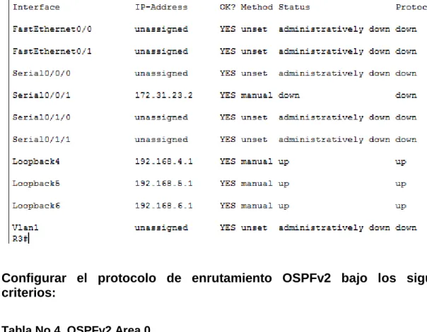
Imagen No 20. Show ip Interface Brief
Configurar el protocolo de enrutamiento OSPFv2 bajo los siguientes criterios:
Tabla No 4. OSPFv2 Area 0
Configuration Item or Task Specification
Router ID R1 1.1.1.1
Router ID R2 5.5.5.5
Router ID R3 8.8.8.8
Configurar todas las interfaces LAN como pasivas
Establecer el ancho de banda para enlaces
seriales en 256 Kb/s
36
Se ingresa al Router 1,(BOGOTA) por medio del comando enable para configurar el OSPF 1.
Configuración OSPF en R1
R1>enable R1#configure t
Enter configuration commands, one per line. End with CNTL/Z. R1(config)#router ospf 1
R1(config-router)#router-id 1.1.1.1
R1(config-router)#Reload or use "clear ip ospf process" command, for this to take effect
R1(config-router)#network 192.168.99.0 0.0.0.255 area 0 R1(config-router)#network 172.31.21.0 0.0.0.3 area 0 R1(config-router)#passive-interface f0/0
R1(config-router)#interface s0/0/0 R1(config-if)#bandwidth 256 R1(config-if)#ip ospf cost 9500 R1(config-if)#interface s0/0/1 R1(config-if)#bandwidth 256 R1(config-if)#exit
R1(config)#exit R1#
%SYS-5-CONFIG_I: Configured from console by console
R1#wr
Building configuration... [OK]
37
Imagen No 21. Show Ip Protocols
Se ingresa al Router 2,(MIAMI) por medio del comando enable para configurar el
OSPF.
Configuración OSPF en R2
R2>enable R2#configure t
Enter configuration commands, one per line. End with CNTL/Z. R2(config)#router ospf 1
R2(config-router)#router-id 5.5.5.5
R2(config-router)#network 209.165.200.224 0.0.0.7 area 0 R2(config-router)#network 172.31.21.0 0.0.0.3 area 0 R2(config-router)#network 10.10.10.10 0.0.0.3 area 0 R2(config-router)#passive-interface f0/0
R2(config-router)#interface s0/0/0 R2(config-if)#bandwidth 256 R2(config-if)#ip ospf cost 9500 R2(config-if)#interface s0/0/1 R2(config-if)#bandwidth 256 R2(config-if)#exit
38
%SYS-5-CONFIG_I: Configured from console by console
R2#wr
Building configuration... [OK]
R2# R2#
Imagen No 22. Router 2 Id
Se ingresa al Router 3,(BUENOS AIRES) por medio del comando enable para configurar el OSPF.
Configuración OSPF en R3
R3>enable R3#configure t
Enter configuration commands, one per line. End with CNTL/Z. R3(config)#router ospf 1
R3(config-router)#router-id 8.8.8.8
R3(config-router)#network 172.31.23.0 0.0.0.3 area 0 R3(config-router)#network 192.168.4.0 0.0.0.255 area 0 R3(config-router)#network 192.168.5.0 0.0.0.255 area 0 R3(config-router)#network 192.168.6.0 0.0.0.255 area 0 R3(config-router)#interface s0/0/0
39
R3(config-if)#ip ospf cost 9500 R3(config-if)#interface s0/0/1 R3(config-if)#bandwidth 256 R3(config-if)#exit
R3(config)#exit R3#
%SYS-5-CONFIG_I: Configured from console by console
R3#wr
Building configuration... [OK]
R3#
Imagen No 23. Router 3 Id
40
Imagen No 24. Show Ip Ospf Interface
1. Configurar VLANs, Puertos troncales, puertos de acceso, encapsulamiento, Inter-VLAN Routing y Seguridad en los Switches acorde a la topología de red establecida
Se ingresa al SWITCH 1 por medio del comando enable, configure t, para configurar la vlan 30,vlan 40,vlan 200 y asignar nombres.
Configuración SW1
Switch>enable Switch#configure t
Enter configuration commands, one per line. End with CNTL/Z. Switch(config)#hostname S1
S1(config)#vlan 30
S1(config-vlan)#name administracion S1(config-vlan)#exit
S1(config)#vlan 40
S1(config-vlan)#name mercadeo S1(config-vlan)#exit
S1(config)#vlan 200
S1(config-vlan)#name mantenimiento S1(config-vlan)#exit
41
%SYS-5-CONFIG_I: Configured from console by console
S1#wr
Building configuration... [OK]
S1#
Configuración de interface fa0/1 en el sw1
S1#configure t
Enter configuration commands, one per line. End with CNTL/Z. S1(config)#interface range fa0/1
S1(config-if-range)#switchport mode access S1(config-if-range)#switchport access vlan 30 S1(config-if-range)#exit
En el Switch 3 deshabilitar DNS lookup
SW3(config)#no ip domain-lookup
5. Asignar direcciones IP a los Switches acorde a los lineamientos. Switch>enable
Switch#configure
Configuring from terminal, memory, or network [terminal]? Enter configuration commands, one per line. End with CNTL/Z. Switch(config)#hostname SW3
SW3(config)#no ip domain-lookup SW3(config)#interface vlan1
SW3(config-if)#ip address 192.168.99.3 255.255.255.0 SW3(config-if)#no shutdown
SW3(config-if)#
%LINK-5-CHANGED: Interface Vlan1, changed state to up
%LINEPROTO-5-UPDOWN: Line protocol on Interface Vlan1, changed state to up
SW3(config-if)#EXIT SW3(config)#EXIT SW3#
%SYS-5-CONFIG_I: Configured from console by console
SW3#WR
42 Configuracion de la interface vlan 1
S1#
S1#enable S1#configure t
Enter configuration commands, one per line. End with CNTL/Z. S1(config)#interface vlan1
S1(config-if)#ip address 192.168.99.2 255.255.255.0 S1(config-if)#no shutdown
S1(config-if)#
%LINK-5-CHANGED: Interface Vlan1, changed state to up
%LINEPROTO-5-UPDOWN: Line protocol on Interface Vlan1, changed state to up S1(config-if)#exit
S1(config)#exit S1#
%SYS-5-CONFIG_I: Configured from console by console S1#wr
Building configuration... [OK]
43
CONCLUSIONES
Configurar las interfaces de los router y switch para el buen funcionamiento de la red.
44
BIBLIOGRAFIA
https://static-course-assets.s3.amazonaws.com/ITN51/es/index.html#10.0.1.1