UNIVERSIDAD POLITÉCNICA DE MADRID
ESCUELA
TÉCNICA
SUPERIOR
DE
INGENIEROS
DE
TELECOMUNICACIÓN
T
ESIS
D
OCTORAL
Sobre el Desarrollo de un Simulador Rápido para
los Sistemas TH-UWB
P
H
D
T
HESIS
On the Development of a Very Fast Simulator for
TH-UWB Systems
Autora:
M
ARINAM
ARJANOVIĆDirector:
D
R.
J
OSÉM
ANUELP
ÁEZB
ORRALLOUNIVERSIDAD POLITÉCNICA DE MADRID
ESCUELA
TÉCNICA
SUPERIOR
DE
INGENIEROS
DE
TELECOMUNICACIÓN
D
EPARTAMENTO DES
EÑALES,
S
ISTEMAS YR
ADIOCOMUNICACIONEST
ESIS
D
OCTORAL
Sobre el Desarrollo de un Simulador Rápido para
los Sistemas TH-UWB
Autora:
M
ARINAM
ARJANOVIĆDirector:
D
R.
J
OSÉM
ANUELP
ÁEZB
ORRALLOEl tribunal nombrado para juzgar la tesis arriba indicada, compuesto de los siguientes Doctores:
Presidente: _______________________________________________________ Secretario: _______________________________________________________ Vocales: _______________________________________________________
_______________________________________________________ _______________________________________________________
Acuerdan otorgarle
Calificación ______________________________________________________
UNIVERSIDAD POLITÉCNICA DE MADRID
ESCUELA
TÉCNICA
SUPERIOR
DE
INGENIEROS
DE
TELECOMUNICACIÓN
D
EPARTAMENTO DES
EÑALES,
S
ISTEMAS YR
ADIOCOMUNICACIONESP
H
D
T
HESIS
On the Development of a Very Fast Simulator for
TH-UWB Systems
Author:
M
ARINAM
ARJANOVIĆAdviser:
D
R.
J
OSÉM
ANUELP
ÁEZB
ORRALLOACKNOWLEDGMENTS
Acknowledgments
There are a number of people who had a major influence in my life for the past
four years. Personally, I believe that they have brought out the best in me and also have
provided the financial and moral support, which played a significant role in my life.
First and foremost, I would like to thank to my supervisor Dr. José Manuel Páez
Borrallo. It was indeed a stroke of enormous good fortune that led me to work with him.
Although extremely busy, professor Páez always could find a time to help me think
about research from a wider perspective. For all his advices, constant encouragements,
giving me the chance to participate in various international conferences where I had met
many interesting people that also had influenced on my work. It has been my privilege
and honour to collaborate with Páez from his days as an energetic professor and director
of ETSIT to his new role as a vice dean of Technical University of Madrid.
Furthermore, I can not skip mentioning many thanks to Dr. Enrique Calleja and
Dr. Angel Álvarez who helped me to become the part of research group GAPS, made
my life in a new country much easier and introduced me to professor Páez.
I like to thank to Dr. Santiago Zazo Bello especially, for offering me good
advices throughout these years, and for getting me project that enable me to cover my
living expenses for the last year.
I am thankful to “Telefónica Móviles” for providing financial support by
granting me a scholarship during the first two and half years; and my sincere gratitude
to “CEDINT”, particularly to its director Ms. Asunción Santamaría for giving me the
chance to attend several international conferences.
I like to thank to Dr. Mariano García Otero for reviewing my first accepted
paper that gave me encouragement to go on. Additionally, I would like to thank to all
anonymous reviewers at conferences who have taken the time to review my work and
provided constructive criticisms and positive feedbacks which have certainly raised the
standard of my work.
I thank to Dr. Santiago Zazo Bello from UPM, to Dr. Javier Ramos López from
ACKNOWLEDGMENTS
Palmas de Gran Canaria’ for their interest in my work and for accepting to be members
of my thesis committee.
Friends that I like to thank include people from GAPS, especially Alberto
Jiménez Pacheco, José Manuel Diaz and Galo Nuño Barrau. Alberto has been very
helpful giving me many fruitful comments and criticism on various versions of my
papers and programs. José Manuel contributed with many handful advices. Of course, I
am thankful to Galo for starting with a wonderful idea and leaving me a space to
continue with working in a very young, interesting and fertile area.
Thanks to my friends Milica, Shiki, Goga, Vlada, Mare, Mica, Marija, Sale,
Jelena Ristic, Jelena Urosevic, Zorana, Zarko, Vaske, Vule, Maja, Grabi, Kum and
Kuma, Sofia, Ful for supporting me during the years towards this dissertation.
I want to thank Mar Díaz Peñalver, Julian Ayuso, Dolores Ajates Abellán, and
Ana Nohales for helping me out with all the administrative issues.
Deepest gratitude should go to my parents and grandparents since they always
have loved me, believed in me, and encouraged me in my study.
Finally, my special thanks should go to Milosh who has been with me and has
been so supportive all these years. Without his love, presence beside me, his
encouragement, support, and technical guidance, this thesis would never have started or
RESUMEN
Resumen
Los impulsos de radio de banda ultra ancha y salto en el tiempo (IR-TH-UWB)
es una tecnología relativamente nueva que puede tener un fuerte impacto en el
rendimiento de las comunicaciones inalámbricas. Resistencia a la propagación
multi-trayecto, bajos niveles de potencia, elevada capacidad, coexistencia con otros sistemas,
capacidad de penetración en paredes, son algunas de las características que hacen que
este sistema sea muy atractivo para Comunicaciones Inalámbricas de corto alcance,
tales como Redes de Área Local inalámbricas (WLAN) y Redes de Área Personal
inalámbricas (WPAN). Esta tecnología hace uso de pulsos de muy corta duración para
transmitir grandes cantidades de datos digitales sobre un rango de frecuencias muy
amplio a muy bajos niveles de potencia. Desafortunadamente, para el procesamiento de
señales de banda ultra ancha, es necesaria una razón de muestreo extremadamente
grande. En una aproximación sencilla, con una razón de muestreo constante, la longitud
del array que contiene las muestras de bits, puede ser muy grande, dependiendo de la
relación entre el ciclo útil y la tasa binaria. Ya que este array tiene que pasar a través de
la cadena de bloques que modela el canal y la respuesta del receptor, es obvio que un
elevado número de convoluciones tienen que ser realizadas. Por lo tanto, aun en
ordenadores muy rápidos, el tiempo total de cómputo para estimar la BER puede ser muy alto. Este hecho reduce considerablemente la eficiencia del simulador. Además,
como se menciona en esta tesis, aplicando descomposición de señal directa/ en
cuadratura a las señales de UWB, que es una técnica fundamental usada para acortar el
tiempo de simulación requerido, no es posible mitigar una elevada frecuencia de
muestreo.
En esta tesis, un sistema TH-UWB con modulación por posición de pulsos
(PPM) es simulado utilizando el simulador de sistema de alta velocidad, el cual
constituye una innovación de nuestro grupo de investigación. Este método aprovecha las
ventajas de algunas de las propiedades de estos tipos de sistemas para facilitar un
RESUMEN
independientemente de la razón de muestreo. Comparándolo con los simuladores
previos, la frecuencia de muestreo puede ser tan elevada como se necesite, ya que el
tiempo de simulación no depende de esta. La señal transmitida es almacenada en el
vector de forma de onda llamado Transmitted Distorted Received (TDR), por lo tanto,
no es necesario operar con las muestras de señal en cada simulación. La única influencia
de la razón de muestreo es en la longitud del vector de forma de onda TDR. La
complejidad del algoritmo es lineal con el número de usuarios, tramas, componentes
multitrayectos y ramas del receptor RAKE.
Para desarrollar el código de simulación, un paso importante en cada proceso de
simulación, es la definición de los atributos del dispositivo físico que afecta los
productos de simulación requeridos, esto es, la tasa de bits erróneos (BER). Uno de estos atributos en sistemas IR-TH-UWB es la sincronización que produce la alineación
de los relojes de relojes en transmisión y en recepción, de manera tal que la información
puede ser intercambiada con exactitud. Particularmente con PPM, la sincronización es
esencial para la correcta demodulación de las señales recibidas, ya que la información es
portada en la posición que tienen los pulsos en el tiempo.
Otra tarea crítica para la operación satisfactoria de los sistemas de UWB es la
detección multi-usuario. Algunas publicaciones muestran que el receptor MMSE tiene
el mejor rendimiento en términos de SINR a expensas de una elevada complejidad de cómputo, ya que requiere de la inversión de la matriz cada vez que la secuencia de
esparcimiento cambia. Por lo tanto, no existe mucha literatura relacionadas con estos
tópicos, especialmente en sistemas de UWB en la presencia de entornos reales con
multitrayecto.
Desafortunadamente, ya que la señal transmitida es almacenada en el vector de
forma de onda TDR, resulta difícil extraerla. Por lo tanto la implementación de aquellas
tareas (sincronización, estimación de canal y detección multi-usuario) podrían ser un
gran problema en la simulación del sistema.
Por lo tanto, la presente tesis se compone de dos partes. En la primera parte se
propone un sistema del tipo PPM IR-TH-UWB con un procedimiento de sincronización
conjunta de símbolo, trama y chip, en un entorno multitrayecto denso. Se asume que el
RESUMEN
dicha sincronización es lograda a partir de maximizar la energía del canal multitrayecto
estimado. Basado en este método para la sincronización en combinación con el método
PWAM para la estimación de canal, las operaciones FFT que son usadas en muchos
trabajos, son evitadas y el algoritmo presenta muy baja complejidad. Adicionalmente y
con la finalidad de incrementar aun más la velocidad del proceso de simulación, este
método es implementado en un algoritmo de ensanchamiento temporal. Por lo tanto, los
algoritmos que esta tesis propone, puede relacionarse con canales con un gran numero
de taps que son difíciles de estimar usando los algoritmos existentes. Gracias a esta
aproximación, una baja complejidad para la implementación en tiempo real y un buen
rendimiento en términos de BER contra relación señal a ruido (SNR) es obtenido. Las simulaciones muestran que estos sistemas sincronizados contribuyan a mitigar los
efectos del corrimiento temporal.
En la segunda parte de la tesis, el receptor MMSE para sistemas IR-TH-UWB
usando un simulador de sistema de alta velocidad, es simulado. La implementación de
cualquier detector multi-usuario fue también una tarea difícil (como lo fue para la
sincronización) ya que una señal transmitida es ‘rechazada’ en los TDR y no existe una
estructura multi-usuario típica con matriz de correlación. Por lo tanto, aplicando este
método en esta tesis, es lograda una nueva aproximación de una detección
multi-usuario. Ya que la forma de onda es almacenada en los TDR, no es necesario operar con
las muestras de señal en cada simulación. Por lo tanto, la matriz de correlación tiene que
ser recalculada solamente cuando las condiciones del canal cambian. Dependiendo del
tiempo de coherencia del canal y de la tasa binaria, es posible encontrar el número de
bits que pueden ser simulados sin alterar la matriz de correlación. La única influencia de
la razón de muestreo es en la longitud de los TDR. Los resultados derivados demuestran
que este efecto es despreciable. Por consiguiente, puede ser considerado que la
velocidad de simulación es aproximadamente independiente de la razón de muestreo.
Ventajas adicionales de esta aproximación es que la complejidad del algoritmo es lineal
con el número de usuarios, las tramas, las componentes multitrayecto y las ramas del
receptor RAKE.
Además, con esta aproximación, es posible reducir el proceso de simulación
RESUMEN
mayor consumo de tiempo. Basados en esta aproximación, un número de operaciones de
simulación necesarias para evaluar la matriz de recepción MMSE son reducidas. Por lo
tanto, es posible procesar un gran número de muestras y estimar exactamente bajos
valores de BER en un corto tiempo. Además, se deriva una fórmula teórica del rendimiento del detector MMSE para PPM IR-TH-UWB basados en esta nueva
aproximación. Esta fórmula es validada a partir de la comparación de los resultados con
otros obtenidos en investigaciones previas.
Ambas tareas, sincronización y la nueva aproximación de detección multiusuario
propuestas en esta tesis, aportan una buena realización en términos de baja complejidad,
procesamiento rápido y un adecuado comportamiento de la BER en función de la relación señal a ruido (SNR).
Todos los resultados son evaluados usando el algoritmo propuesto y las
simulaciones son facilitadas para validar esta implementación. Estas demuestran que el
tiempo de simulación crece linealmente con el número de usuarios y el número de
tramas. El principal logro de esta tesis es un algoritmo para el cálculo de un sistema
completo PPM IR-TH-UWB cuya complejidad es Nh veces inferior comparado con
resultados previos, donde Nh es un número de chips en aquellos sistemas. Por lo tanto,
asumiendo un factor de esparcimiento grande de las señales de UWB, este algoritmo
consigue salvar un elevado tiempo de cómputo comparado con los diseños previos.
Esta tesis está constituida por seis capítulos. En el primer capítulo se ofrece una
panorámica de los fundamentos de los sistemas de UWB y dentro de este, algunos
tópicos incluyen: historia de UWB, características y aplicaciones de estos sistemas.
En el segundo capítulo se incluye el diseño de un sistema de acceso múltiple
UWB, incluyendo el diseño de un transmisor es revisado. Este capítulo presenta el
modelo completo del sistema y el convenio de notaciones empleadas a lo largo de la
tesis.
También en el segundo capítulo se incluyen dos modelos estadísticos para
canales de UWB son presentados, basados en datos reunidos a partir de medidas
extensivas de la propagación UWB. Saleh-Valenzuela y basado en Saleh-Valenzuela,
modelo propuesto por Intel que será empleado con estos propósitos en la tesis, será
RESUMEN
En adición, se proporciona una descripción de una estructura receptora de simple
usuario y multiusuario, asumiendo una sincronización y una estimación de la canal
perfecta que constituyen la contribución de esta tesis.
El capítulo cuatro cubre las siguientes tareas:
• Diferencias entre UWB y sistemas tradicionales de banda estrecha y dificultades
en el desarrollo del modelo.
• Una breve revisión de los fundamentos de las metodologías de simulación.
• Un nuevo simulador del sistema IR-TH-UWB que constituye un aporte de
nuestro grupo de investigación y que será utilizado en interés de esta tesis.
El capítulo cinco presenta la segunda parte de la contribución de esta tesis donde
he implementado un receptor RAKE MMSE para sistemas de UWB usando un nuevo
simulador de sistema de salto en tiempo, logrando una novedosa aproximación de
detector multiusuario (MUD). Adicionalmente, es presentada una nueva fórmula teórica
del rendimiento del detector MMSE para PPM IR-TH-UWB basado en esta nueva
aproximación y en investigaciones previas es presentado.
El capítulo seis presenta resultados de las simulaciones para verificar este
ABSTRACT
Abstract
Impulse Radio-Time Hopping-Ultra Wideband (IR-TH-UWB) is a relatively
new technology that might have a big effect on improving wireless communication.
Multipath resistance, low power, high capacity, coexistence with other systems, ability
of penetrating walls are some of the characteristics that make this system very attractive
for a Short Range Wireless Communications, such as deployed in Wireless Local Area
Network (WLAN) and Wireless Personal Area Network (WPAN). This technology uses
short pulses in order to transmit large amounts of digital data over a wide spectrum of
frequency bands with a very low power. Unfortunately, in order to process
ultra-wideband signals, an extremely large sampling rate is mandatory. In a straightforward
approach, with the constant sampling rate, the length of the array that contains the bit
samples can be very large, depending on the relationship between the duty cycle and the
bit rate. Since this array should pass through the chain of blocks that model the channel
and receiver responses, it is obvious that a large number of convolutions should be
done. Thus, even in very fast workstations, the total computing time in order to estimate
BER can be very high. This fact significantly reduces the efficiency of the simulator. Furthermore, as mentioned in this thesis, applying direct/quadrature signal
decomposition to UWB signals, which is fundamental technique used to shorten the
required simulation runtime, it is not possible to mitigate a large sampling frequency.
In this thesis, a complete Pulse Position Modulation (PPM) TH-UWB system is
simulated using the high-speed system simulator, which is the innovation of our
research group. This method takes advantage of some of the properties of this kind of
systems in order to provide a very straightforward and fast processing that improves all
the previous designs several orders of magnitude, independently on the sampling rate.
Comparing to previous simulators, sampling frequency can be as high as needed, since
the simulation run-time does not depend on it. Transmitted signal is stored in the
Transmitted Distorted Received (TDR) waveform vector, thus it is not necessary to
ABSTRACT
rate is on the length of the TDR waveform vector. The algorithm complexity is linear
with the number of users, frames,multipath components, and rake fingers.
In order to develop the simulation code, an important step in every simulation
process is definition of the attributes of the physical device that affect the required
simulation products, i.e. Bit Error Rate (BER). One of those attributes in IR-TH-UWB
systems is synchronization that produces alignment of transmitter and receiver clocks,
so information can be accurately exchanged. Particularly with PPM, synchronization is
essential to correct demodulation of the received signals because information is
conveyed in the time position of the pulse.
Another critical task for successful operation of UWB systems is a multiuser
detection. Some papers show that MMSE receiver has the best performance in terms of
SINR at the expense of high computational complexity since it requires the matrix inversion every time the spreading sequence changes. Thus, there are no many
literatures dealing with this topic, especially not in UWB systems in the presence of real
multipath environment.
Unfortunately, since the transmitted signal is stored in the TDR waveform
vector, it is very difficult to extract it. Thus, implementation of those tasks
(synchronization, channel estimation and multiuser detection) might be a big problem
for system simulation.
Therefore, this thesis has two main parts. In the first part of the thesis, a joint
symbol, frame and chip synchronization method for PPM IR-TH-UWB system in the
presence of dense multipath environment is proposed. It is assumed that the channel is
estimated using Pilot Waveform Assisted Modulation (PWAM), and that
synchronization is achieved by maximizing the energy of the estimated multipath
channel. Based on this method for synchronization in combination with PWAM method
for channel estimation, FFT operations that are used in many works are avoided and the
algorithm has a very low complexity. Additionally, in order to even more increase the
speed of simulation process; this method is implemented in the enhanced time
algorithm. Therefore, algorithm that this thesis proposes can deal with channels with a
large number of taps that are difficult to estimate using the existing algorithms. Thanks
ABSTRACT
performance in terms of BER versus Signal to Noise Ratio (SNR) are achieved. Simulation shows that this synchronization system helps to mitigate the negative effects
of timing offset.
In the second part of the thesis, MMSE receiver for PPM IR-TH-UWB systems
using a high-speed system simulator is implemented. Implementation of any multiuser
detector in this algorithm was also a difficult task (as was for synchronization), since a
transmitted signal is ‘hidden’ in TDR and a typical multiuser structure with a correlation
matrix does not exist. Therefore, applying this method, in this thesis, a new approach of
multiuser detection is achieved. Since the transmitted waveform is stored in the TDR, it
is not necessary to operate with the signal samples in every simulation. Thus,
correlation matrix should be recalculated only when the channel conditions change.
Depending on the channel coherence time and the bit rate, it is possible to find the
number of bits that can be simulated without alerting the correlation matrix. The only
influence of the sampling rate is the length of the TDR. Derived results show that this
effect is disregarded. Therefore, it can be considered that the simulation speed is
approximately independent on the sampling rate. Additional advantage of this approach
is that the complexity of the algorithm is linear with the number of users, frames,
multipath components, and RAKE fingers.
Furthermore, with this approach, it is possible to reduce the simulation process
significantly by avoiding any convolution operation, which is the most time-consuming.
Relaying on this approach, number of simulation operations needed to evaluate MMSE
receiver matrix are reduced. Thus, it is possible to process a large number of samples
and to estimate accurately low BER in a short time application. In addition, I derived a
theoretical formula of the performance of the MMSE detector for PPM IR-TH-UWB
based on this new approach. This new formula is validated by comparing results to
some other results based on some previous researches.
Both tasks, synchronization and the new approach of multiuser detection
proposed in this thesis, give a good performance in terms of low complexity, fast
processing and BER versus Signal to Noise Ratio (SNR) performance.
All results are evaluated using the proposed algorithm and simulations are
ABSTRACT
time linearly grows with the number of users and the number of frames. The main gain
of this thesis is that the complexity of the algorithm in order to calculate the complete
PPM IR-TH-UWB system is Nh times lower comparing to previous methods, where Nh
is a number of chips in those systems. Therefore, assuming a large spreading factor of
the UWB signals, this algorithm yields a large saving of computational time comparing
to the previous designs.
With this accurate flexible simulation model; we might analyze the performance
of the TH-UWB system and the impact of different factors of TH-UWB systems (the
number of users, waveform design time-hopping codes, channel models, receivers…)
and achieve a low BER in a real time application even in the presence of reach multipath environment.
This thesis consists on five chapters. In the first chapter of this thesis, the
fundamentals of UWB system are overviewed. Within the following sections, topics
covered are UWB history, features and applications of UWB system, types of UWB
signals, UWB spectrum and regulations and some of the possible problems of this
system.
The second chapter gives an overview of MA UWB system design, including a
transmitter design. Additionally, this chapter presents the overall system model and
notation convention that I have used throughout this thesis.
In addition, two statistical models for UWB channel are presented based on data
collected from extensive UWB propagation measurements. Saleh-Valenzuela and based
on Saleh-Valenzuela, model proposed by Intel that will be employed for the purposes of
this thesis are described. This channel model was made with one slight modification
since the observations have shown that the lognormal distribution better fits the
measurement data.
Additionally, the second chapter provides a description of a single user and
multiuser receiver structure, assuming perfect synchronization and perfect channel
estimation. As an optimum single user receiver, selective RAKE receiver is used for the
purposes of this thesis and as a multiuser receiver, MMSE RAKE is employed.
In addition, as a one part of the contribution of this thesis low complexity
ABSTRACT
time implementation and the good performance in terms of BER versus SNR are achieved.
Since the UWB system requires taking a second look at simulation
methodology, the chapter three covers the following tasks:
• Differences between UWB and traditional narrowband systems and difficulties
in model development
• A brief review of the fundamental simulation methodologies.
• New IR-TH-UWB system simulator that is the innovation of our research group
and will be used for the purposes of this thesis.
In Chapter four, I implemented a MMSE RAKE receiver for Ultra-Wideband
(UWB) system using a new time-hopping system simulator, achieving a novel approach
of MUD. With this approach, it is possible to reduce the simulation time significantly by
avoiding any convolution operation, which is the most time-consuming. Relaying on
this approach, number of simulation operations needed to evaluate MMSE receiver
matrix are reduced. Complexity of this algorithm is O(Nu*Nf*L*Lmax), while using
Monte Carlo method complexity is Nh times higher. Thus, for systems with a very large
spreading factor, as UWB is, this provides a large computational time saving.
Additionally, I have derived a theoretical formula of the performance of MMSE
RAKE receiver detector for PPM IR-TH-UWB based on this new approach and some
previous researches.
In chapter five, simulation results are provided in order to validate this approach.
TABLE OF CONTENTS
Table of Contents
1. Summary... 31
1.1. Introduction... 31
1.2. UWB History ... 32
1.3. Features and Applications of UWB ... 34
1.4. UWB Signal Definition ... 36
1.4.1. Types of UWB Signals ... 36
1.4.1.1. IR-UWB Versus MC-UWB ... 36
1.5. UWB Compatibility with Other Services ... 40
1.6. UWB Problems ... 42
1.7. Conclusion ... 43
2. UWB System Model... 45
2.1. Introduction... 45
2.2. Multiple Access IR-UWB Signal Structure and Signal Model ... 46
2.2.1. Pulse Shapes ... 47
2.2.2. Modulation Schemes ... 49
2.2.3. TH Sequences ... 50
2.3. The MC-UWB System Model ... 51
2.3.1. Overview of the MC-UWB System ... 51
2.3.2. OFDM UWB ... 52
2.4. UWB Multipath Channel ... 52
2.4.1. Introduction ... 52
2.4.2. Saleh-Valenzuela Model ... 53
2.4.2.1. Proposed Model Based on Intel Measurements ... 57
2.5. Single User Receiver Structure... 65
2.5.1. Introduction ... 65
2.5.2. Selective RAKE Receiver ... 66
2.5.2.1. Performance of a PPM TH-UWB System employing RAKE Receiver ... 68
2.6. Multiuser Detection (MUD) Receivers... 71
2.6.1. Performance of a PPM TH-UWB System employing MMSE RAKE Receiver 74 2.6.2. Synchronization and Channel Estimation ... 75
2.6.3. Transmitted Reference UWB Receiver ... 77
TABLE OF CONTENTS
2.6.5. Synchronization ... 82
2.6.6. Conclusion... 84
3. The Slowness of Simulating TH-UWB System... 87
3.1. Introduction... 87
3.2. Differences between UWB and Traditional Narrowband Systems ... 88
3.2.1. Large Sampling Frequency... 88
3.2.2. Difficulties in Model Development... 91
3.3. A Brief Review of BER Estimation Techniques ... 92
3.3.1. Monte Carlo Simulation Techniques... 93
3.3.2. Importance Sampling Technique... 94
3.3.3. Semi-Analytic Simulation Technique ... 96
3.4. High Speed System Simulator ... 98
3.4.1. Signal and noise separation. Signal processing ... 99
3.5. Conclusion ... 105
4. A Novel Approach of Multiuser Signal Model for Simulation Purposes... 107
4.1. Introduction... 107
4.2. A Novel Approach of Multiuser Signal Model for AWGN Channel ... 108
4.3. A Novel Approach of Multiuser Signal Model for Synchronous Channel... 111
4.4. MMSE RAKE Receiver Implementation ... 112
4.5. Theoretical Performance of the MMSE Receiver-Based on the Novel Approach .... 116
4.6. Conclusion ... 118
5. Simulation Results ... 121
5.1. Introduction... 121
5.2. Single User Receiver ... 122
5.2.1. Number of Users Influence on BER Performance in AWGN Channel... 122
5.2.2. Number of Chips Influence on BER Performance in AWGN Channel... 123
5.2.3. Type of the Monocycle Influence on BER Performance in AWGN Channel 124 5.2.4. Sampling Frequency Influence on BER Performance in AWGN Channel .... 125
5.2.5. Influence of Different Parameters on BER Performance in the Multipath Channel 126 5.2.6. Synchronization and Channel Estimation ... 127
5.3. Time Performance and Complexities of the algorithm... 132
5.4. Multiuser Receiver... 134
5.4.1. Number of Users Influence on BER Performance in the AWGN Channel Employing MMSE RAKE Receiver ... 135
TABLE OF CONTENTS
5.4.3. Sampling Frequency Influence on BER Performance in AWGN Channel
employing MMSE Receiver ... 137
5.4.4. Number of Users Influence on the BER Performance in the Channel2 Employing MMSE RAKE Receiver ... 138
5.4.5. Number of Chips Influence on BER Performance in the Channel2 Employing MMSE RAKE Receiver ... 139
5.4.6. Sampling Frequency Influence on BER Performance in the Channel 2 employing MMSE Receiver ... 140
5.4.7. Number of Users Influence on BER Performance in the Channel 3 Employing MMSE RAKE Receiver ... 141
5.4.8. Number of Chips Influence on BER Performance in the Channel 3 Employing MMSE RAKE Receiver ... 142
5.4.9. Number of RAKE Fingers Influence on BER Performance in the Channel 2 Employing MMSE RAKE Receiver ... 145
5.4.10. Effect of the Synchronization on BER Performance for a PPM-TH-UWB System with MMSE Receiver in the presence of Channel 2... 146
5.5. Time Performance and Complexities of the Algorithm... 147
6. Conclusions... 153
6.1. Thesis Summary ... 153
6.2. Summary of the Contributions... 155
ABBREVATIONS
Abbreviations
AGN Additive Gaussian Noise
AWGN Additive White Gaussian Noise
BEP Bit Error Probability
BER Bit Error Rate
DS Direct Sequence
FCC Federal Communications Commission
FH Frequency Hopping
FT Fourier Transform
GPS Global Positioning System
GSM Global System for Mobile
LAN Local Area Network
LPD/I Low Probability of Detection/Interception
MAC Medium Access Control
MC Multi Carrier
MMSE Minimum Mean Square Error
MRC Maximum Ratio Combining
MSE Mean Square Error
MUD Multi-User Detection
MUI Multiuser Interference
(N)LOS (Non) Line Of Sight
OFDM Orthogonal Frequency Division Multiplexing
OMAN Open Mobile Access Network
PAM Pulse Amplitude Modulation
PDF Probability Distribution Function
PPM Pulse Position Modulation
PSD Power Spectral Density
ABBREVIATIONS
RF Radio Frequency
QoS Quality of Service
SINR Signal-to-Noise-plus-Interference-Ratio
SNR Signal-to-Noise-Ratio
SS Spread Spectrum
SUD Single-User Detection
TDMA Time Division Multiple Access
TDR Transmitted-Distorted-Received
TEM Transverse Electromagnetic
TH Time Hopping
TR Transmitted Reference
UAV Unmanned Aerial Vehicle
UGV Unmanned Ground Vehicle
UMTS Universal Mobile Telecommunication System
UWB Ultra-Wideband
WAN Wide Area Network
WLAN Wireless Local Area Network
WPAN Wireless Personal Area Network
LIST OF FIGURES
List of Figures
Figure 1.1 Comparison of the Fractional Bandwidth of a Narrowband and Ultra
Wideband Communication System ...37
Figure 1.2. Spectrum of a Gaussian Monocycle- Based Impulse UWB Signal
(Data taken from [48])...38
Figure 1.3. Spectrum of an OFDM based MC-UWB Signal (Data taken from [48]) ....39
Figure 1.4. UWB Spectral Mask and FCC Part 15 Limits. (Data taken from [49])...40
Figure 1.5. WPAN, WLAN, and Cellular Networks: Typical Link Ranges. (Data
taken from [49])...41
Figure 2.1. Frame Structure for TH Signals ...46
Figure 2.2. Example UWB Pulses ...47
Figure 2.3. PSD of the Different UWB Pulses ...48
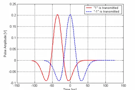
Figure 2.4. Example of a PPM Modulate UWB Signal Using the Data Sequence
{1 -1} ...50
Figure 2.5. Example of a PAM Modulate UWB Signal Using the Data Sequence
{1 -1} ...51
Figure 2.6. Channel Impulse Response ...55
Figure 2.7. Exponential Decay of Mean Cluster Power and Ray Power Within
LIST OF FIGURES
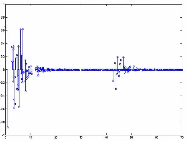
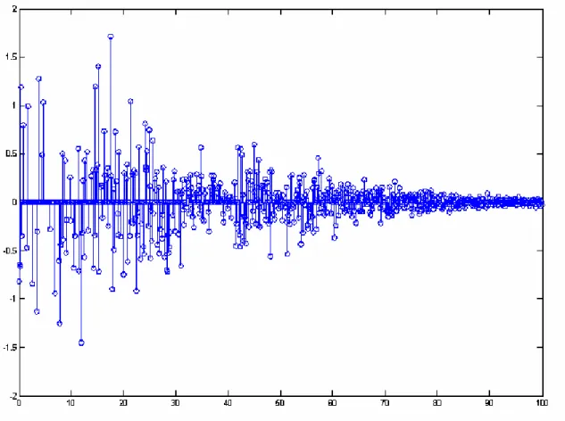
Figure 2.8. One LOS Channel Realization Generated From Intel Model Using the
Same Parameter as the Ones in Table 2.2. (Experimental Data taken
from [76]) ...61
Figure 2.9. One NLOS Channel Realization Generated from Intel Model Using
the Same Parameter as the Ones in Table 3.3. (Experimental data taken
from [76]) ...62
Figure 2.10. RAKE Receiver Structure Scheme ...67
Figure 2.11 Histogram of the distribution of the MUI for a PPM TH-UWB system
with Tc=1 ns, Nh= 1024slots, Nu=900 links, λ = 180 ps, Nf=64 and no
multipath. The number of simulations is 330.503. It can be noticed the
Gaussian distribution of the interference. (Data taken from [83]) ...69
Figure 2.12. Theoretical BER Performance versus SNR of a PPM TH-UWB
System Downlink Employing RAKE Receiver in a Multipath Channel;
L=100, Nf=64; Nh=128...70
Figure 2.13. Theoretical BER Performance of a PPM TH-UWB System
Employing RAKE Receiver vs. BER Performance of a PPM TH-UWB
System Employing MMSE Receiver in AWGN Channel; Nf=8; Nh=4;
Nu=5 ...75
Figure 2.14. Block Scheme of the Receiver (with Channel Estimation and Joint
Synchronization)...77
Figure 2.15. Illustration of the Transmitted Reference System...78
Figure 2.16. Illustration of the PWAM Scheme...79
LIST OF FIGURES
Figure 2.18. Timing Offset Presentation ...84
Figure 3.1. Wideband Signal Spectrum...90
Figure 3.2. Schematic Representation of Implementation of Monte Carlo Method ...94
Figure 3.3. Importance Sampling Illustration...95
Figure 3.4. Diagram of a Semi-Analytic BER Calculation for BPSK...97
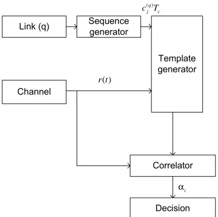
Figure 3.5. Conceptual Model of the UWB Receiver for the qthUser ...103
Figure 3.6. Signal Processing Flowchart ...104
Figure 4.1. Signal Processing Flowchart (as in [83]) ...112
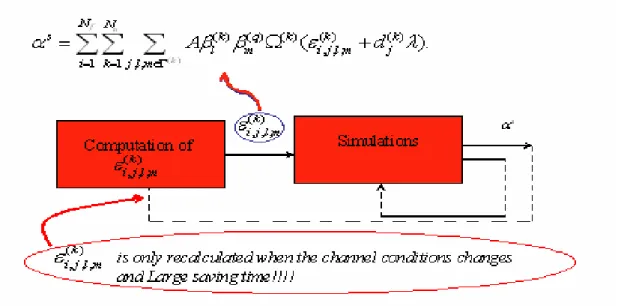
Figure 4.2. Error Vector Calculation Flowchart...114
Figure 4.3. Simulator Flowchart...115
Figure 4.4. Position Vector Calculation Flowchart ...116
Figure 4.5.Comparison Between the Theoretical and Results Obtained with New
Approach for AWGN and NLOS Channel; Γ=16 γ=8.5, 1/Λ=11 ns,
1/λ=0.35 ns, L=400, Lmax=400;Nu=5; Nf=8; Nh=4 ...118
Figure 5.1. Number of Users Influence on BER performance employing Single
User Receiver; Second Derivative of the Gaussian Monopulse; AWGN
channel; Nf=32, Nh=64, fs=200/Tc...122
Figure 5.2. Number of Chips Influence on BER performance employing Single
User Receiver; Second Derivative of the Gaussian Monopulse; AWGN
channel; Nu=64, Nf=64, fs=200/Tc,...123
Figure 5.3. Monocycle Shape Influence on BER performance employing Single
LIST OF FIGURES
Figure 5.4. Sampling Frequency Influence on BER performance employing Single
User Receiver; Second Derivative of the Gaussian Monopulse; AWGN
channel; Nu=64, Nh=64, Nf=8, Nh=4 ...125
Figure 5.5. BER performance employing Single User Receiver; Second Derivative
of the Gaussian Monopulse; Multipath Channel L=400, Nu=2, Nh=64,
Nf=32, fs=200/Tc...126
Figure 5.6. UWB Downlink System Model ...127
Figure 5.7. UWB Uplink System Model ...127
Figure 5.8. Channel Estimation Performance in the PPM TH-UWB System
Downlink employing RAKE Receiver in NLOS Multipath Channel
based on Intel Measurements from Figure 3.4; Lmax=18, Nu=13, Nf=32,
Nh=128, fs=200/Tc, Perfect Synchronization ...128
Figure 5.9. Channel Estimation Performance in the PPM TH-UWB System
Uplink employing RAKE Receiver in NLOS Multipath Channel from
Figure 3.4 based on Intel Measurements; Nu=13, Nf=32, Nh=128,
fs=200/Tc, Perfect Synchronization...129
Figure 5.10. BER Performance versus SNR of a PPM TH-UWB System Downlink
employing RAKE Receiver in NLOS Multipath Channel from Figure
3.4 based on Intel Measurements; Lmax=18, Nu=13, Nf=32, Nh=128,
Np=10000, fs=200/Tc...130
Figure 5.11. BER Performance versus SNR of a PPM TH-UWB System Uplink
LIST OF FIGURES
Figure3.4 based on Intel Measurements; Nu=13, Nf=32, Nh=128,
Np=10000, fs=200/Tc...131
Figure 5.12. Relation between the Sampling Frequency and the Simulation Time
per Bit for a PPM-TH-UWB System with PWAM assuming
Synchronization; SNR=5dB, Np=1, fs=200/Tc...132
Figure 5.13. Effect of the Number of Multipath Components on the Simulation
Time per Bit for a PPM-TH-UWB System with PWAM assuming
Perfect Synchronization; SNR=5dB, Np=1, fs=200/Tc...133
Figure 5.14.Comparison Between Results from [85] and Results Obtained with a
New Approach; L=1 (AWGN); Nu=5, Nf=8, Nh=4, fs=200/Tc...134
Figure 5.15. Effect of the Number of Users on BER Performance for a
PPM-TH-UWB System with MMSE Receiver; Nh=4, Nf=8, Tc=2 ns, fs=200/Tc,
L=1 ...135
Figure 5.16. Effect of the Number of Chips on BER Performance for a
PPM-TH-UWB System with MMSE Receiver; Nu=5, Nf=8, Tc=2 ns, fs=200/Tc,
L=1 ...136
Figure 5.17. Sampling Frequency Influence on BER performance employing
MMSE Receiver; Second Derivative of the Gaussian Monopulse;
AWGN channel; Nu=64, Nh=64, Nf=8, Nh=4...137
Figure 5.18. Effect of the Number of Users on BER Performance for a
PPM-TH-UWB System with MMSE Receiver; Nh=4, Nf=8, Tc=2 ns, fs=200/Tc,
Γ=16, γ =8.5, 1/Λ=11 ns, 1/λ=0.35 ns, L=400, Lmax=400
LIST OF FIGURES
Figure 5.19. Effect of the Number of Chips on the BER Performance for a
PPM-TH-UWB System with MMSE Receiver; Nu=5, Nf=8, Tc=2 ns,
fs=200/Tc, Γ=16, γ =8.5, 1/Λ=11 ns, 1/λ=0.35 ns, L=400, Lmax=400
(Channel2) ...139
Figure 5.20. Sampling Frequency Influence on BER performance employing
MMSE RAKE Receiver; Second Derivative of the Gaussian
Monopulse; Channel 2; Nu=5, Nh=4, Nf=8 ...140
Figure 5.21. Effect of the Number of Users on BER Performance for a
PPM-TH-UWB System with MMSE Receiver; Nh=4, Nf=8, Tc=2 ns, fs=200/Tc,
Γ=33, γ =5, 1/Λ=2 ns, 1/λ=0. 5 ns, L=400, Lmax=400 (Channel3)...141
Figure 5.22. Effect of the Number of Chips on BER Performance for a
PPM-TH-UWB System with MMSE Receiver with Nh=4, Nf=8, Tc=2 ns,
fs=200/Tc, Γ=33, γ =5, 1/Λ=2 ns, 1/λ=0. 5 ns, L=400, Lmax=400
(Channel3) ...142
Figure 5.23. Effect of the Number of Users on the BER Performance for a
PPM-TH-UWB System with MMSE Receiver in the presence of AWGN
channel vs. BER Performance for a PPM-TH-UWB System in the
presence of Channel 2; Nh=8, Nf=8, Tc=2 ns, fs=200/Tc, L=400,
Lmax=400 ...143
Figure 5.24. Effect of the Number of Chips on BER Performance for a
PPM-TH-UWB System with MMSE Receiver in the presence of AWGN
LIST OF FIGURES
MMSE Receiver in the presence of Channel 2; Nu=8, Nf=8, Tc=2 ns,
fs=200/Tc, L=400, Lmax=400...144
Figure 5.25. Effect of the Number of RAKE Fingers on BER Performance for a
PPM-TH-UWB System with MMSE Receiver in the presence of
Channel 2; Nu=8, Nf=8, Nh=4, Tc=2 ns, fs=200/Tc, L=400 ...145
Figure 5.26. Effect of the Synchronization on BER Performance for a
PPM-TH-UWB System with MMSE Receiver in the presence of Multipath
Channel (Channel2) Nu=13, Nf=8, Nh=8, Tc=2 ns, fs=200/Tc, L=400,
Lmax=400. ...147
Figure 5.27. Relation between the Sampling Frequency and the Simulation Time
per Bit for a PPM-TH-UWB System employing MMSE RAKE
Receiver; Nu=5, Tc=2 ns, fs=200/Tc, Nf=8, Nh=4, L=400, Lmax=100...148
Figure 5.28. Effect of the Number of Users on the Simulation Time per Bit for a
PPM-TH- UWB System employing MMSE RAKE Receiver; Tc=2 ns,
fs=200/Tc, Nf=8 Nh=4, L=400, Lmax=100...149
Figure 5.29. Effect of the Number of Multipath Components on the Simulation
time per Bit for a PPM-TH- UWB System with MMSE Receiver;
Nu=5, Tc=2 ns, fs=200/Tc, Nf=8, Nh=4, Lmax=L...149
Figure 5.30. Effect of the Number of Frames on the Simulation Time per Bit for a
PPM-TH- UWB System with MMSE Receiver; Nu=5, Tc=2 ns,
fs=200/Tc, Nh=4, L=400, Lmax=100. ...150
Figure 5.31. MMSE Matrix Calculation Flowchart using our Algorithm vs.
LIST OF FIGURES
Figure 6.1. Conceptual Model of the UWB Signal Generation...157
Figure 6.2. Conceptual Model of the UWB Receiver for the qthUser ...158
Figure 6.3 Optimum Combining UWB RAKE Receiver for IR-TH-UWB ...161
Figure 6.4. Error Vector Calculation Flowchart when Optimum RAKE Receiver
LIST OF TABLES
List of Tables
Table 2.3. Simulated and Measured Results for NLOS UWB Channels Using
Intel’s Model. Simulation Results are Generated from Intel Model with
Γ=16 ns, γ=8.5 ns, Λ=1/11 ns, λ=1/0.35 ns, σ =4.8 dB. (Experimental
data taken from [76]) ...61
Table 2.4. Example Multipath Channel Characteristics and Corresponding Model
Parameters (Experimental data taken from [76]). ...63
Table 5.1 Channel Estimation Performance in the PPM TH-UWB System
Downlink employing RAKE Receiver in NLOS Multipath Channel
based on Intel Measurements from Figure 3.4; Lmax=18, Nu=13, Nf=32,
Nh=128, fs=200/Tc, Perfect Synchronization ...128
Table 5.2 Channel Estimation Performance in the PPM TH-UWB System Uplink
employing RAKE Receiver in NLOS Multipath Channel from Figure
3.4 based on Intel Measurements; Nu=13, Nf=32, Nh=128, Perfect
Synchronization ...129
Table 5.3. BER Performance versus SNR of a PPM TH-UWB System Downlink
employing RAKE Receiver in NLOS Multipath Channel from Figure
3.4 based on Intel Measurements; L=400; Lmax=18; Nu=13; Nf=32;
Nh=128; Np=10000...130
Table 5.4. BER Performance versus SNR of a PPM TH-UWB System Uplink
LIST OF TABLES
3.4 based on Intel Measurements; Lmax=18, Nu=13, Nf=32, Nh=128,
Np=10000, fs=200/Tc...131
Table 5.5. Comparison of the Algorithms Complexities...133
Table 5.6 Comparisons of the Algorithms Complexities in Single User Receiver ...151
CHAPTER 1 SUMMARY
Chapter 1
1.
Summary
1.1.
Introduction
Ultra wideband (UWB) communication systems can be broadly classified as any
communication systems whose instantaneous bandwidth is many times greater than the
minimum required to deliver particular information. This large bandwidth is the
defining characteristic of those systems.
Within the past 40 years, advances in analog and digital electronics and UWB
signal theory have enabled system designers to propose some practical UWB
communications system. Over the past decade, many individuals and corporations
began asking the FCC for permission to operate unlicensed UWB system concurrent
with existing narrowband signals. In 2002, FCC decided to change the rules to allow
UWB system operation in a broad range of frequencies. In some of the FCC UWB
rule-making process proceedings, one of them can find a vast array of claims relating to the
expected utility and performance of UWB systems, some of them almost perfect.
Testing by the FCC, FAA, and DARPA has uniformly shown that UWB still conforms
to Maxwell’s Equations and the laws of physics.
It is a relatively new technology that might have a big effect on improving
wireless communications. Multipath resistance, low power, high capacity, coexistence
with other systems, ability of penetrating walls are some of the characteristics that make
this system very attractive for a Short Range Wireless Communications, such as
deployed in WLAN and WPAN [1]-[3]. This technology uses short pulses in order to
transmit large amounts of digital data over a wide spectrum of frequency bands with a
SUMMARY CHAPTER 1
In this chapter, the fundamentals of UWB system are overviewed. Within the
following sections, topics covered are UWB history, features and applications of UWB
system, types of UWB signals, UWB spectrum and regulations and some of the possible
problems of this system.
1.2.
UWB History
There is a comprehensive bibliography about the origins of the UWB technology
as in [5]-[34]. Dr. Henning F. Harmuth gave a descriptive history of no sinusoidal
electromagnetic technologies in [13]-[19]. In his work, it was found that in late 1950's,
there was a first effort made by Lincoln Laboratory and Sperry to develop phased array
radar system.
The analysis started in attempting to understand the wideband properties of the
needed network. The four-port interconnection of quarter wave TEM mode lines was
analysed.
The impulse response of these networks was a train of weighted and equally
spaced impulses, thus the response resembled what one would find at the output of a
sampled data system. About the same time, Schmidt and RWP King were measuring the
impulse response of the dipole and resonant ring radiating elements in the time domain.
The response in the far field and the driving ports was approximately a train of
uniformly spaced impulses that was well correlated with the work of Hallen. Dr. Hallen
found in the frequency domain that this class of radiating element had a periodic
amplitude spectrum. This fact made clear that working in the time domain, was correct
for analysis and provided a challenge. With the help of Dr. Barney Oliver at Hewlett
Packard, who had just developed the sampling oscilloscope, and the generation of very
short pulses using avalanche transistors and tunnel diodes, the UWB technology started
to evaluate. The former Sperry Research Centre Sudbury then continued the work, in
1965 where this writer formed a group of very talented engineers to help with the
further development of this technology. Dr. J. Lamar Allen expanded the analysis of
CHAPTER 1 SUMMARY
Harry Cronson later extended the work to time domain metrology where the frequency
domain properties of passive microwave networks were found via their impulse
response and Fourier transforms (FT). Both the US Air Force at Rome Labs and the US
Army in Huntsville, Alabama supported this work. At this time, Drs. David Lamensdorf
and Leon Susman started the analysis of antennas using time domain techniques.
The final task that needed to be developed before real system development
began was the threshold receiver. In the early 1970's both avalanche transistor and
tunnel diode detectors were constructed in an attempt to detect these very short duration
signals. Dr. A. Murray Nicolson of the tunnel diode constant false alarm rate receiver
improved this work in the development. This improved version of this receiver detector
is still in use today. With all the system blocks in place, a short-range radar sensor was
developed as a pre-collision sensor for the airbag and used later in cars (1972). The
range of this sensor was about 8 feet. Later improvements in power generation
techniques resulted in a space docking radar (25-30 feet) and an aircraft runway traffic
sensor with a range of 300 feet. Many systems that require different range requirements
were developed, including a new class of altimeters. In the metrology area (1970-1980),
this writer together with Dr. Nicolson developed a narrow base band pulse fixture to
measure the properties of microwave absorbing materials directly from a single pulse
measurement. Most of the development of those stealthy materials done at Wright
Patterson AFB used this approach until the Hewlett Packard network analyzer became
available. This was used to develop an anti-collision system for unmanned vehicles in
work and later this technique was expanded to measure liquid levels in a tank.
Work in radar continued in the 1990's with the development of synchronized
arrays of short pulse sources. Peak powers in the order of 100 kW (peak base band
power) were achieved using low cost sources designed to radiate and scan in space
microwave pulse packets having pulse durations on the order of 1-3 ns. These systems
were used for the detection applications.
In 1978, efforts turned toward the communication of these signals. Voice signals
were transmitted reliably over hundreds of feet without the need for synchronization and
SUMMARY CHAPTER 1
greater ranges using the 19 kHz sub carrier from classical music frequency modulated
stations in urban areas.
During the period 1984-1994, the work in communications was considerably
expanded working together with Dr. Robert J. Fontana.
Until now, over 200 papers were published in accredited IEEE journals and
more than 100 patents were issued on topics related to ultra wideband technology. Due
to the reach area of applications, the business interests for UWB technology are growing
exponentially.
1.3.
Features and Applications of UWB
Since the duration of used monopulses is extremely short, there are many
features of the UWB system, summarized as follows:
• High data rate performance
This is important for communications where UWB pulses can be used to provide
extremely high data rate performance in multi-user network applications.
• Fine range resolution and precision distance
This fact allows quality for radar applications [35], [36].
• Multipath resistance
Consequently, UWB systems are well suited for high-speed, mobile wireless
applications. Multipath cancellation occurs when a strong reflected wave arrives
out of phase with the direct path signal, producing a reduced amplitude response
in the receiver. With very short pulses, the direct path has come and gone before
the reflected path arrives avoiding the cancellation. In addition, implementation
of the RAKE receiver improves multipath resistance [36], [38].
• Low interference with other systems
This fact is significant for both military and commercial applications, since this
low energy density translates into a low probability of detection (LPD) RF
signature. An LPD signature is of particular interest for military applications
CHAPTER 1 SUMMARY
produces minimal interference to proximity systems and minimal RF health
hazards as it was shown in [39], [40].
• Low system complexity and low cost
UWB systems can be made nearly "all-digital", with minimal RF or microwave
electronics. Due to the inherent RF simplicity of UWB designs, these systems
are highly frequency adaptive, enabling them to be positioned anywhere within
the RF spectrum. According to [39], this feature avoids interference to existing
services, while fully utilizing the available spectrum.
• The UWB system always occupies a wide bandwidth (order of GHz)This
insures a high capacity multiple access and ultra high-speed transmission (<
Several hundreds of Mbps). According to the classification of [41], applications
of the UWB system can be divided on military and civil. In the military and
government marketplace, these applications include:
• Tactical Handheld & Network LPI/D Radios
• Non-LOS LPI/D Ground wave Communications
• LPI/D Altimeter/Obstacle Avoidance Radar
• Tags (facility and personal security, logistics)
• Intrusion Detection Radars
• Precision Geolocation Systems
• Unmanned Aerial Vehicle (UAV) and Unmanned Ground Vehicle (UGV)
• Data links
• LPI/D Wireless Intercom Systems
While civil applications include:
• High Speed (20+ Mb/s) LAN/WANs
• Altimeter/Obstacle Avoidance Radars (commercial aviation) Collision
Avoidance Sensors
• Tags (Intelligent Transportation Systems, Electronic Signs)
• Intrusion Detection Radars
• Precision Geolocation Systems
SUMMARY CHAPTER 1
As for the commercial marketplace, however, there are currently no "approved"
applications within the United States, since the frequency approval for UWB operation
has yet to be acted upon by the Federal Communications Commission (FCC).
1.4.
UWB Signal Definition
In order to define an UWB signal, the following definition for the fractional
bandwidth is employed:
2 H L
f
H L
f f
B
f f
− =
+
(1.1)
where fL and fH represent the lower and upper frequencies (3 dB points) of the signal
spectrum, respectively. Thus, as it was defined in [41] and [42], UWB signals are
signals that have a fractional bandwidth greater than 25% in contrast to narrowband
signals with fractional bandwidth less than 1%. Figure 1.1 presents the comparison of
the Fractional Bandwidth of a Narrowband and Ultra wideband communications
systems.
1.4.1. Types of UWB Signals
There are two forms of UWB. First is IR-UWB, based on transmitting
information sending a very short duration pulses and the second is MC-UWB, based on
using multiple simultaneous carriers.
1.4.1.1. IR-UWB Versus MC-UWB
The relative advantages and disadvantages of those two types of signal are
CHAPTER 1 SUMMARY
One of the issues is minimizing interference transmitted by, and received by the
UWB system. In MC-UWB it is possible to choose carrier frequencies to avoid
narrowband interference or from narrowband system. Therefore, it might be considered
Figure 1.1 Comparison of the Fractional Bandwidth of a Narrowband and Ultra
Wideband Communication System
that MC-UWB is well suited for avoiding interference. The most common form of
multicarrier modulation, OFDM, has become the leading modulation for high data rate
systems.
In addition, MC-UWB vs. IR-UWB is more flexible and scalable, but requires
an extra layer of control in the physical layer. However, for both types of UWB signals,
IR-UWB and MC-UWB spread spectrum techniques can be applied in order to reduce
SUMMARY CHAPTER 1
IR-UWB signals need fast switching time for the transmitter and receiver and
very high precise synchronization between them. Since IR-UWB has a high
instantaneous power during the very short interval of the pulse, it can better avoid
interference to UWB systems, but, on the other hand, this high instantaneous power
increases the possibility of interference from UWB to narrowband systems. In addition,
IR-UWB are very low-cost systems since they can be made nearly "all-digital", with
minimal RF or microwave electronics.
Figure 1.2. Spectrum of a Gaussian Monocycle- Based Impulse UWB Signal (Data
taken from [48])
On the other hand, MC-UWB systems have a number of advantages over their
CHAPTER 1 SUMMARY
therefore higher bit communications. In addition, MC-UWB has simpler channel
synchronizations, which leads to low-cost transceiver implementation and has the
continuous variations in power over a very wide bandwidth. Therefore, implementing a
MC-UWB front end can be challenging. This might be particularly challenging for the
power amplifier. UWB-OFDM is a novel MC-UWB system that uses a frequency
hopping scheme for reliable high bit rate communication over multi-path fading
channels [46]. The main advantage of UWB-OFDM system over normal OFDM is its
fine time resolution and ability to resolve multipath. Changing a frequency selective to
several parallel flat fading channels, OFDM system has not such high multipath
resistance [47].
Figure 1.2 and Figure 1.3 illustrates a comparison of the spectrum of IR-UWB
and MC-UWB, respectively.
SUMMARY CHAPTER 1
1.5.
UWB Compatibility with Other Services
UWB technology offers simultaneously high data rate communication and high
accuracy positioning capabilities as it was mentioned before. These systems can utilize
low transmitted signal power level with extremely wide bandwidth. Due to the very low
PSD, UWB systems can co-exist with the other radio systems.
The FCC recently approved the deployment of UWB on an unlicensed basis in
the 3.1–10.6 GHz band [49]. The essence of this ruling is to limit the PSD measured in a
MHz bandwidth. UWB spectral mask and FCC part 15 limits are shown in Figure 1.4.
Figure 1.4. UWB Spectral Mask and FCC Part 15 Limits. (Data taken from [49])
The spectral mask allows UWB enabled devices to overlay existing systems
while ensuring sufficient attenuation to limit adjacent channel interference. Additional
CHAPTER 1 SUMMARY
The first consequence of this spectral mask imposed by the FCC is to express the use of
base band pulse shapes without additional transmit filtering.
Figure 1.5. WPAN, WLAN, and Cellular Networks: Typical Link Ranges. (Data taken
from [49])
In summary, UWB communications are allowed at a very low average transmit
power compared to more conventional (narrowband) systems that effectively restricts
UWB to short ranges [50]. UWB is thus, a candidate physical layer mechanism for
IEEE 802.15 WPAN for short-range high-rate connectivity that complements other
wireless technologies in terms of link ranges. Typical Link Ranges limits of WPAN,
WLAN, and Cellular Networks is shown in Figure 1.5. One of the main problems,
according to the compatibility, is interference caused by UWB signals to other various
radio systems, as well as the performance degradation of UWB systems in the presence
of narrowband interference and pulsed jamming. An UWB system suffers most from
PAN
LAN
WAN
Short-Range
Range
0-10m 0-100m 0-1
SUMMARY CHAPTER 1
narrowband systems if the narrowband interference and the nominal centre frequency of
the UWB signal are overlapping. This is proved in [41] by BER simulations in an AWGN channel with interference at global system for GSM and UMTS/WCDMA
frequencies. In the in-band interference study, the victim radio systems are
UMTS/WCDMA, GSM900, and GPS. It is shown that better results are achieved with
proper selection of UWB pulse waveform and their width for spectral planning. Using
short pulses, interference in the observed frequency bands is the smallest if the pulse
waveform is based on higher order Gaussian waveforms.
When the UWB system degradation is studied in the presence of an interfering
and jamming radio system, results show that the system performance suffers most if the
interference and the nominal centre frequency of the UWB system are overlapping.
Thus, the UWB performance depends on the pulse waveform and on the pulse width. It
is shown that for high data rates, short pulses should be used. Additionally, it is shown
that the third derivative of the Gaussian pulse performs better than the first derivative.
On the other hand, if the data rate demands are not so high, and long pulses can be used,
then lower order waveforms perform better.
1.6.
UWB Problems
As with any technology, there are always applications that may be better served
by other approaches. Therefore, there are still some problems related to UWB systems.
• In order to process ultra-wideband signals, it is necessary to have an extremely large sampling rate.
As it was mentioned in the abstract, in a straightforward approach, with the constant
sampling rate, the length of the array that contains the bit samples can be very large,
depending on the relationship between the duty cycle and a bit rate. Since this array
should pass through the chain of blocks that model the channel and receiver responses,
it is obvious that a large number of convolutions should be done. Thus, even in very fast

![Figure 1.2. Spectrum of a Gaussian Monocycle- Based Impulse UWB Signal (Data taken from [48])](https://thumb-us.123doks.com/thumbv2/123dok_es/6770427.830606/42.892.146.730.371.912/figure-spectrum-gaussian-monocycle-based-impulse-signal-data.webp)


![Figure 2.7. Exponential Decay of Mean Cluster Power and Ray Power Within clusters (taken from [76])](https://thumb-us.123doks.com/thumbv2/123dok_es/6770427.830606/60.892.161.730.147.570/figure-exponential-decay-mean-cluster-power-power-clusters.webp)