Plasma basic concepts and
Nitrogen containing plasmas
Marfa del Mar Sanz1 and Isabel T a n a r r o2
'ISOM-Univ. Politecnica Madrid (UPM). ETSIT, Ciudad Universitaria Madrid-28040-Spain; 2lnst. Estructura de la Materia, CSIC, Serrano 123 Madrid-28006-Spain
Abstract
1. Introduction
Why do we present this chapter, dedicated to plasma topic, within a book devoted to the growth, characterization and devices of nitrides and dilute nitrides?
One of the most extensively used methods to grow both nitrides and dilute nitrides is by using MBE. In this case, nitrogen plasmas are commonly used as a source of reactive nitrogen.
This chapter is proposed to give a practical overview about basic concepts related to plasmas. Though the information given here is surely already familiar to this book's readers, it may be useful to have the basic concepts all together in a brief chapter. Plasma behaviour implies a good number of complex processes which open a wide and diverse field of applications.
In the following sections, the exposition of the basic concepts and fundamental parameters will be treated in such a way, that the minimum possible number of mathematical expressions will be given. Though the discussion will be limited basically to cold plasmas at low pressure, a general overview of the different plasma systems and some applications of other kind of plasmas applied in surface treatment will be briefly exposed. There are good references [1-3], where detailed explanation from a more rigorous point of view can be found regarding plasma behaviour and its applications in material processing.
Although plasma processing has become a routine and critical step in the fabrication of microelectronic devices, plasma remains a powerful, yet unexploited technology. So far, the development of plasma processing in low pressure electric discharge reactors has been carried out mostly by trial and error methods, by changing external reactor parameters in order to develop the best achievable film properties; but meanwhile, the intrinsic state of the plasma has remained largely unknown. However, the processes of interest can be characterized and controlled, and the final material optimized much more properly, when the nature of the main active species formed in the plasma from the gas precursors can be identified, and internal plasma parameters such as the densities of ions and radicals, and the energy distributions of electrons and heavier species are well known.
We hope that after reading the next sections, some useful information can be obtained in order to better understand and characterize the plasmas used in the nitride growth, thus helping the readers to optimize their own processes.
2. Basic concepts
2.1. Definition of p l a s m anumbers of free positive and negative charges, in a "quasi-neutral" condition. It is produced when part of the atoms or molecules in the gas become ionized and is sometimes referred to as the fourth state of matter, distinct from the solid, liquid and gaseous states.
Nearly all the visible matter in the universe exists in the plasma state. It is the constituent of the Sun and stars and occurs in interplanetary and interstellar space. Auroras, lightning, flames, fluorescent tubes and welding arcs are also plasmas and they exist in many other phenomena and objects. The Earth itself is immersed in a tenuous plasma called the solar wind and is surrounded by a more dense plasma called the ionosphere.
From a scientific point of view, the basic distinction among solids, liquids and gases lies in the difference between the strength of the bonds that hold their constituent particles together. These binding forces are relatively strong in a solid, weak in a liquid, and essentially almost absent in the gaseous state. Whether a given substance is found in one of these states depends on the random kinetic energy (thermal energy) of its atoms or molecules as compared with the inter-particle binding forces. Plasma is usually obtained when an amount of energy, higher than that needed for ionization, is added to the neutral particles of a gas, causing the production of free ions and electrons. But parallel to the ionization processes, electrons recombine with ions or in the walls to form neutral species, and the plasma tends to get extinguished. The process is usually ignited and sustained by providing electromagnetic energy to the gas in different forms: direct current, radio frequency, microwaves and so on. Electric discharges in gases at low pressures are just the usual way to produce plasmas for microelectronic devices applications; but plasmas can also be obtained when sufficient energy is provided to a liquid or a solid to cause its vaporization and ionization, usually by means of a high power laser.
The word plasma comes from the Greek and means "moulded". The existence of plasmas was predicted by Michael Faraday in 1820, but it was Irving Langmuir and collaborators who first studied this medium while working in 1929 on the development of vacuum tubes for large currents, and who first used the term "plasma" to describe the glowing inner region, remote from the boundaries, of the discharge tubes.
and negative charges at long distances, forcing them to move along irregular curved paths, which on average follow the electric field, and give the plasma its characteristic collective behaviour.
2.2 Fundamental parameters in plasmas
The word plasma is used to describe a wide variety of macroscopically neutral substances containing many interacting free electrons and ionized atoms or molecules, which exhibit collective behaviour. Not all media containing free charged particles, however, can be classified as plasmas. They must satisfy certain conditions, or criteria, which will be discussed in this section, being characterized mainly by the following parameters.
2.2.1. Basic parameters
The main and basic parameters in plasmas are: • The density of neutral particles, N„.
• The densities of electrons, Ne, and positive ions, N, (in most plasmas
negative ions are not found and they will be neglected here).
• The energy distributions of neutral particles, f„(E), ions, J](E), and electrons, fe(E).
In the natural quasi-neutral state of the plasma, densities of electrons and ions are equal and Ne=Nt is called the plasma density. The parameter that
defines the fraction of the particles which are ionized in the medium is the
degree of ionization, a= N/N„. In fusion plasmas, lightning and stars, the
plasma is fully ionized, however, for plasmas sustained in low-pressure discharges, the degree of ionization is typically 10"6 to 10"3, although it can
reach values higher than 10"2 if the electrical discharge is assisted and confined
by a magnetic field.
inefficient in kinetic energy transfer, E^., since it is determined by the mass ratio of the colliding particles
tr M
where M is the mass of the heavy particle, E, the electron energy, and m., the electron mass, roughly 1800 times smaller than the mass of the lightest H atom. Therefore, the kinetic energy distributions of electrons and heavy species in the plasma can be very different, especially if the degree of ionization and, consequently, the frequency of collisions between electrons and heavy species is low. On the contrary, a significant amount of energy is easily transferred in one elastic collision between two electrons. In this case, electrons acquire average kinetic energies of several electron-volts, while molecules and ions remain close to ambient temperature, giving thus rise to a state of non-equilibrium. For a Maxwell distribution, 1 eV of electron mean kinetic energy, E, implies an electron temperature, Te = 11600 K, some two times the
temperature of the Sun surface; while at 300 K, the ambient temperature, the mean energy of particles is 0.025 eV.
2.2.2. Secondary parameters:
Another important parameter of plasmas is the Debye length. If an electric field is applied to a plasma, the charged particles, mainly the lighter, more mobile, electrons, will move to counteract and shield the effect of the field by creating a local space charge. This effect of local neutralization of electric fields, which lets the rest of the plasma keep its quasi-neutral state, is called Debye shielding. The Debye length is the characteristic dimension of the regions in which breakdown of neutrality (formation of local predominant concentrations of charges of one sign) can occur in a plasma. Its value is given by [2]
I
'D£0kTe
ne2
where e0 is the permitivity of vacuum, Te, the electron temperature, and e, the
charge of the electron. For estimation purposes, it is useful to calculate the
Debye length from
AJJ \cm) = 6.93— j= 743 j -ne (cm ) «g (cm )
When a solid surface is in contact with the plasma, ions and electrons reaching the surface recombine or are implanted on it, and are lost from the plasma system. Electrons are quicker than ions and go out from the plasma much faster, leaving a net positive charge in the vicinity of the surface. Consequently, the surface acquires a negative potential relative to the plasma. This layer of positive space charge, existing around all surfaces in contact with the plasma, is called the plasma sheath. Its dimensions depend on the geometry, pressure and external bias applied to the surface, but its thickness is usually some ten times the value of the Debye length. An ionized gas is considered a plasma when the electron density is large enough to imply a
Debye length much smaller than the plasma dimensions, so that regions with
charge quasi-neutrality are clearly predominant over the plasma sheath regions. The movement of electrons in the plasma in response to any electric perturbation will manifest through oscillations. Due to their much larger mass, the ions will respond much more slowly. The characteristic frequency of these electron oscillations is called the plasma frequency or Langmuir frequency. The larger the free electron density, the stronger the electrostatic restoring force in this oscillatory motion and the higher the plasma frequency cop, which is given by [2]
<v
r i \1 / 2
\meeQj
•-1.8• 1037t^N~e (Hz) for K expressed in (cm-3).
For a plasma density of 1010 cm"3, the plasma frequency is 9T08 Hz, much
higher than the 13.56 MHz commonly used to sustain a radio frequency discharge. These simple predictions are modified in the presence of electron-neutral collisions. If electrons collide too frequently with electron-neutral species, their motion is controlled by ordinary hydrodynamic forces rather than by electromagnetic forces and the collective behaviour condition of the plasma is not satisfied.
In the context of the interaction of electromagnetic waves with plasmas, a^ marks a fundamental boundary between their conductor and dielectric behaviour. When the frequency of the incident wave is large compared with the plasma frequency, the inertia of electrons retards their response and the plasma behaves as a dielectric. As a result, the plasma is mostly transparent to the radiation. When the incident wave frequency is less than CDp, the electrons readily respond so as to exclude the incident field, resulting in reflection of wave energy from the plasma. As an example, the D region of the ionosphere, where Ne is about 108 m"3, forms a conductive waveguide for electromagnetic
The expression given above for (Op is valid too for the characteristic oscillations of electrons in a solid conductor. Metals, in which Ne is about 1028 m"3, are
good reflectors at all electromagnetic frequencies up to the optical range, but become translucent in the ultraviolet or X rays region.
2.3 K i n d s of plasmas
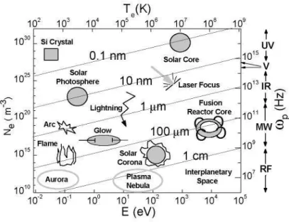
Bearing in mind former description of the main plasmas characteristics, the difference between gases and plasmas can be now summarized and understood better, even in the case of gases with a low degree of ionization. Gases are formed by essentially independent particles, in which energy transfer and particle behaviour are determined by dynamic forces and individual collisions. Plasmas, with a much higher content of free charges and internal energy, are characterized by the collective behaviour of their charged species, because in them, the electro-magnetic forces are much stronger than the dynamic forces.
Te(K)
102 1 03 104 105 106 107 108 109
10"2 10"1 10° 101 102 1 03 104 105
E(eV)
Figure 1. Different kinds of natural and artificial plasmas (see text)
particles). At the right axis, the corresponding plasma frequencies with the different spectral ranges of the electromagnetic spectrum are shown. All these scales are given in powers often. Sloping lines inside the graph, show different values of the Debye length, ranging from 0.1 run to 1cm as displayed.
With regard to the electron temperature, and being TN and TN+ the
temperatures of neutrals and ions, plasmas spread from hot plasmas, where Te~
TN,TN+, to cold plasmas, where Te > TN,TN+. Considering the ionization degree,
plasmas can be classified from weakly ionized plasmas, where Ne / Nn < 10"3,
to highly ionized plasmas, where the ionization degree may reach values close to one. Highly ionized plasmas are the Sun and stars, lightning, or those found in the core of thermonuclear fusion reactors. Weakly ionized plasmas are for example the Earth ionosphere, glow discharges, plasmas found in the interstellar space and so on. In order to compare the orders of magnitude of electron concentrations, a (non plasma) silicon crystal is displayed at the upper-left hand side of Figure 1.
Cold plasmas, with Te > TN,TN+, are systems far from thermodynamic
equilibrium. It is worth noting that electron temperatures in cold plasmas are often remarkably higher than those of hot plasmas, whereas the temperatures of neutrals and ions can be much lower. In contrast to cold plasmas, hot plasmas have usually a high degree of ionization. As far as the efficiency of kinetic energy transfer from electrons to heavier species increases with the ionization degree and, as a result, with the number of collisions, electrons loose their energy gained from the electric field and transfer it to ions and neutrals, heating them. The name "cold plasma" refers mainly to the temperature of heavy species. Due to their special characteristics, cold plasmas generated at low pressure by "glow" discharges are of special interest in the context of film deposition.
The relationship between the current and voltage in a low-pressure gas discharge is displayed in Fig. 2 showing the four characteristic regions of "dark" or "Townsend discharge' prior to spark ignition, "normal glow", "abnormal glow" and "arc discharge" where the plasma becomes highly conductive. The second and third regions tend to shrink with increasing pressure. For many gases, ignition proceeds directly to arcing at 1 atm.
1000
0 A 1 1 1 1 1 1 1—
10-5 10-4 10"3 10"2 10"1 10° 101 102
Current (A)
Figure 2: Relationship between the current and voltage in a low-pressure gas discharge
modify their surfaces, or, if initially conductive, they can be covered by insulating material along the deposition process without extinguishing the discharge. The use of external electrodes coupled to discharge reactors made of quartz or pyrex allow a reduction of the effects of sputtered impurities coming from the electrode materials.
2.4 Kinetics of cold plasmas generated in glow discharges
Cold plasmas have the unique property of efficiently generating chemically active species at low gas temperatures. The non-equilibrium steady-state conditions created by the high-energy electrons can transform a normally inert molecular gas such as N2 into a highly reactive medium. The
main advantage of plasma assisted surface processing of solid samples by glow discharges stems from the fact that the active precursors needed to modify or grow films on the surfaces are produced at temperatures noticeably lower than those required with thermal reactions at thermodynamic equilibrium. Therefore, surfaces of materials that do not have enough thermal stability to withstand high temperatures can be tailored properly with this kind of plasmas. In addition, the lower temperatures in the plasma are important when it is necessary to limit diffusion or grain growth, especially in microelectronic processing.
When an electric field is applied to a gas, plasma ignition is possible thanks to the free electric charges existing previously, produced by the background of ionizing radiation which relies on cosmic rays and natural radioactivity. At sea level, some 103 free electrons per cubic centimetre are
potential, Vb, depends on pressure, P, and discharge gap width, d, and is given
by Paschen curves, different for each kind of gas, which can be expressed as:
y
A-p-d
b
B + ln(p-d)
where A and B are constants that change with the nature of the gas. Figure 3 displays this curve for air.
105
>
o
Q_
O
• o | 103
1 02 H 1 1 . 1
0.1 1 10 100 1000 Pd (cmTorr)
Figure 3: Paschen curve for air, showing the relationship between the breakdown
potential and the product of air pressure and distance between electrodes.
In DC glow discharges at very low pressures, an additional source of free accelerated electrons such as those produced by an incandescent filament at a given high voltage can reduce the breakdown potential. A reduction of this potential takes place too when a strong magnetic field concentrates the electrons, as it happens for example in magnetron plasma sources. In AC discharges each electrode acts alternately as anode and cathode and charged particles oscillate following the electric field. When the frequency of the field increases above a critical value, first the slow ions and then the fast electrons begin to change their direction gaining energy from the field without touching the electrodes. In these cases the voltages required to initiate the discharge decrease strongly in comparison to a DC glow discharge and the efficiency of ionizations and dissociations increases.
e + AB e + AB -e + A -> e + AB e + AB e + AB e + AB
--> e + AB -» e + A + B
• 2 e + A+
-> 2 e + AB+
-^AB~ ->A + B" -> e + A+ + I
A —> e + A* Atom excitation (electronic)
Molecular excitation (rotational, vibrational, electronic) Molecular dissociation (A, B: atoms or radicals) Atom ionization
Molecular ionization (cation formation) Molecular ionization (anion formation) Dissociative attachment
B~ Dissociative ionization
Parallel to the generation of plasma species, loss processes also take place. Electrons are lost mainly by diffusion to the surfaces exposed to the plasma. Ions are similarly lost by diffusion and neutralization in the wall, and they can return to the plasma as neutrals or be implanted in the material. Ions impinging on the walls liberate new secondary electrons which contribute to sustain the plasma, with a probability which depends on ion energy and surface conditions. Ions are lost also by recombination with electrons in the gas phase through reactions like:
e + A+ —> A + hv Radiative recombination e + AB+ —> A + B Dissociative recombination
Neutral atoms and radicals are lost by recombination through reactions in the gas phase (homogeneous reactions) with other transient or stable species, or through reactions on the walls of the reactor (heterogeneous reactions), producing other transient or molecular products, with reactions like:
AB + C —> A + BC Two-body reaction (molecule + atom or radical) A + B + C —> AB + C Three-body reaction
A + B + wall —> AB + wall Heterogeneous reaction
Two body reactions between stable molecules can be neglected in cold plasmas, due to the low values of the corresponding rate coefficients, that scale usually with exp(TN). Reactions between two active species (ions, atoms or
radicals) can be disregarded too, since the concentrations of both species are very low.
Although three-body homogeneous reactions may be very important in plasmas at higher pressures, they can be omitted in glow discharges because the probability of three-body collisions, which is proportional to P2, is very
plasmas, since reactions like N+N—>N2, which needs a third body to occur in
gas phase, are only possible in the walls at low plasma pressures.
The effectiveness of each kind of interaction between two species in the gas phase is determined by the reaction coefficient, which depends on the relative velocities between the colliding particles, their respective densities and the reaction cross section. Cross sections are specific for each kind of reaction and depend on gas temperature and internal excitations of colliding particles. Extensive data compilations on rate coefficients for homogeneous reactions involving neutral and ion species are available in the literature [5,6]. In particular, a very complete review of reactions involved in nitrogen and oxygen containing plasmas is given in ref [7]. Presently, reliable kinetic modelling of plasmas is frequently hindered by a noticeable lack of data concerning dissociation and ionization cross sections by electron impact, especially at low electron energies. Reaction coefficients for surface processes are mostly unknown too, and they depend on the energy of the colliding particles and on surface conditions such as temperature, kind of material, cleanliness, etc.
3. Plasma diagnostics
As mentioned in the introduction, so far, the development of plasma processing in low pressure electric discharge reactors has been carried out mostly empirically, by changing external reactor parameters such as power, frequency of power supply, pressure, geometry, gas flow rate or gas mixture ratio, in order to develop the best achievable film properties; whereas, the intrinsic plasma behaviour has been usually ignored. However, the material characteristics can be controlled much better when the nature of the main active species formed from the gas precursors is identified, and internal plasma parameters such as the densities of ions and radicals, and the energy distributions of electrons and heavier species are well known. To obtain a complete set of these plasma parameters, very useful measurement techniques, complementary and different to those employed for the surface characterization, are presently available.
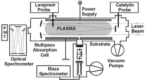
include light absorption methods, mainly from ground state species, and emission spectroscopy from excited states. Mass spectrometry can be used to detect ions and neutral species. Electric probes, mostly "Langmuir" probes, allow the measurement of electric charge densities and electron energies. Figure 4 shows a schematic set-up with some of these techniques. Catalytic probes, depicted too in figure 4 have been recently developed to measure the concentrations of reactive atoms such as N, O or H [8]. A classic book describing the different techniques used for plasma diagnostic is ref [9].
Langmuir Probe
<5>
Power Supply
Catalytic Probe
Optical Spectrometer
Laser Beam
Multipass Absorption
Cell
Mass Spectrometer
i =
Vacuum Pumps
Figure 4: Schematic configuration of the most commonly used diagnosis techniques to characterize plasmas.
Emission spectroscopy has been used during decades to identify the excited species with high precision and sensitivity, although estimations of absolute concentrations from emission data are usually quite difficult. Dispersive instruments are employed for visible and ultraviolet transitions and Fourier transform spectrometers for the infrared region. Actinometry allows to get the relative concentration of several species as compared with that of another one introduced at very low density in the discharge, by measuring the intensities of some lines of each species for which the electron energy dependence of excitation cross sections are similar and transition probabilities and other relevant parameters are known [10,11]. The "actinometer" is usually argon or another noble gas. A very useful book describing the different spectroscopic techniques presently available is given in ref. [12].
spectroscopic techniques for the study of molecular transitions. The absolute concentrations values can be directly inferred from absorption measurements when the absorption coefficients for the studied transitions are known. Tuneable high resolution laser sources combined with optical multi-pass configurations like that shown in Figure 4 are often very advantageous for absorption spectroscopy of species at very low densities [13] or when chemically complex plasmas with spectrally very close transitions of the different species are found [14]. Lasers have also allowed the development of other very sensitive and selective techniques such as laser induced fluorescence (LIF) and resonance-enhanced multiphoton ionization (REMPI)
[15].
Electron temperature, plasma density and plasma potential are measured with single or double Langmuir probes inserted into the plasma, by recording the characteristic curve of the electrons and ions current arriving to the probe as a function of the applied positive and negative voltage, respectively. Continuous improvements of this method for different kinds of plasmas are being developed. A recent revision is found in ref [16].
Mass spectrometry by means of quadrupole mass spectrometers with ionization of neutral species by electron impact and detection of the corresponding ions, is a very popular and sensitive technique to detect molecules in plasmas and gases. Nevertheless, ionized fragments of the parent molecules are also formed in the ionizers of the mass spectrometers, giving rise to characteristic fragmentation patterns for each molecule. In this case, some peaks of the fragmentation patterns of the different molecules may overlap and perturb the identification of the species in complex plasmas. A quite complete text concerning mass spectrometry is ref. [17]. Mass spectrometry of ions with analysis of the ion energy distribution functions, [18] ion attachment mass spectrometry, [19] and mass spectrometry at threshold energies for radical detection, [20] are also very useful tools for plasma diagnostics, which have added new possibilities to the conventional mass spectrometry.
4. Plasma applications
4.1 General considerations
Up to here, we have tried to show the basic concepts relating to plasmas classification, generation, behaviour, diagnosis and modelling from the simplest point of view. As it has already been mentioned, and everybody can see, "plasmas study" covers a truly wide area connecting different disciplines and there are many parameters that can make plasma behavior to drastically change. Therefore, the field of plasmas finds a wide and interesting spectrum of applications; from the purely analytical spectrochemistry to plasma confinement in fusion reactors; from lamps to gas lasers or plasma display panels. Plasmas find well-established use in industrial applications (e.g. surface modification, lasers, lighting, etc.), but they are also gaining more interest in the field of life sciences, related to environmental issues and biomedical applications.
It has already been discussed as well, that there are different kinds of plasmas depending on all the mechanisms involved at different conditions. If we try to make a brief discussion about the different applications, according to all possible plasma configurations and properties, we could write not a whole book, but some complete collection. Fortunately there exist some good books and references where the reader can find well explained fundamentals of the different techniques where plasmas are applied and their importance [1-3 and references within].
For the sake of this chapter extension (and its readers health), we will limit this part to the most common applications of gas discharge plasmas. We will focus, though, on the applications concerning surface modifications and related topics.
4.2 Gas discharge plasma applications
There are some reviews about gas discharge plasmas and their application. In reference [24], there is a complete overview about different kind of gas discharge plasmas and their main applications. Here, we will just condense the applications in Table 1 with some interesting references where the reader can find useful information for further reading. However, we will very briefly describe the kind of discharge and pressure ranges used in the different applications.
1. Analytical applications
magnetron discharges, DC plasma jets and Surface Wave Discharges (SWD) have also been used for analytical purposes.
Table 1. Some gas discharge plasmas applications and related references:
Application
1. Analytical 2. Lamps
3. Plasma displays 4. Lasers
5. Ozone generation 6. Environmental 7. Biomedical
8. Surface treatment and modifications
References
[25-271 [28-32] [33-37] [38-43], [331, [44-451 [46-511 [2], [52-57]
See below, section 4.3
2. Lamps
Several types of light sources are based on gas discharge plasmas. We can find the conventional electroded lamps and the more recent types of
electrodeless discharge lamps. They both can operate as low-pressure,
non-LTE {Local Thermal Equilibrium) lamps (e.g. fluorescence lamps) and high-pressure, thermal LTE-lamps (e.g. High-Intensity Discharge (HID) lamps).
Examples of electroded low-pressure lamps are the fluorescence lamps, which operate in the positive column of a DC glow discharge, in a mixture of a rare gas with mercury. The electroded high pressure lamps, (also called HID) operate in the regime of an arc discharge, with typical pressures of some atmospheres. Examples are High Pressure Mercury lamps (HPM) and High Pressure Sodium lamps (HPS) which do not need the presence of phosphorous to produce visible light.
3. Plasmas Displays
Until now, the television (TV) market has been dominated by bulky Cathode Ray Tube (CRT) displays. Recently, two alternative display technologies have emerged that offer the possibility of large, lightweight, flat TV monitors. Both are based on small gas discharges: microdischarges1. The
'Microdischarges are gas discharges where the anode-cathode distance is reduced
most well-known is the Plasma Display Panel (PDP) technology, using microdischarges to generate the light of the display. The other one is the Plasma Addressed Liquid Crystal (PALC) technology. This is a variation of the LCD (Liquid Crystal Display), which is currently widely used. Similar to LCDs, PALC displays do not generate light but they modulate the light generated by a source behind the display. The modulation in LCD takes place thanks to the electro-optical properties of the liquid crystal: it changes the polarization of the light passing through the crystal, acting as switches, whereas in PALC displays, microdischarges serve as electrical switches.
4. Lasers
Several kinds of gas lasers exist, but for them all, the mechanism of population inversion, necessary for laser action, always occurs via gas discharges. The gas, at reduced pressure, is contained within a glass discharge tube with mirrors at the tube end. Anode and cathode can be placed at both ends of the tube. Alternatively, the cathode can have hollow cathode geometry, with anode rings at the ends. Generally, three classes of gas lasers can be distinguished, depending on whether the lasing transition occurs between energy levels of atoms (i.e. He-Ne lasers), ions (i.e. Argon ion laser) or molecules (i.e. C02, excimer lasers).
5. Ozone generation
Ozone (03) generation is a typical application of Dielectric Barrier
Discharges (DBD)2 or high pressure Glow Discharges (GD). Ozone can be
generated from oxygen, air or from other N2/02 mixtures. The first step
towards ozone formation in gas discharge is the dissociation of 02 molecules
by electron impact and by reactions with N atoms or excited N2 molecules, if
nitrogen is present. Ozone is then formed in a three body reaction involving O and02.
6. Environmental Applications
In the above application, DBDs serve as chemical reactor to produce ozone. A similar use, but with different reactions, makes plasmas (both thermal and non-thermal) interesting for environmental applications. The thermal plasmas mostly used for this purpose include several kinds of arcs, as well as
the processes taking place in the discharge. The field of microdischarges is an emerging research topic with many potential advantages and applications[57].
2Historically, they are also known as "silent discharges". They operate at
ICPs. Thermal plasmas offer some unique advantages for the destruction of hazardous wastes compared to classical combustion.
The non-thermal plasmas used for environmental applications are mainly high pressure discharges such as DBDs, pulsed corona discharges.
7. Biomedical applications
Another increasing application field of gas discharges, mostly at atmospheric pressures, is for biomedical applications. Plasmas are used to improve the biocompatibility of materials. Surfaces of biomaterial polymers employed in biomedical products are typical materials modified by plasma treatment. Plasma sterilization of biological samples, mainly by Atmospheric Pressure Gas Discharge (APGD), is also gaining interest in the healthcare industry. A plasma exposure time of several minutes leads to a reduction in the population of microorganisms by six orders of magnitude.
4.3 Surface treatment and modification
As A. Grill pointed out in his book [2]:
...Processing by plasma assisted techniques is being increasingly used in various areas of production and manufacturing as diverse as the automotive, aerospace, and biomedical industries and in the fabrication of microelectronic components. The current predominant trend in the microelectronics industry is to switch
increasingly from wet to dry processing of materials by plasma assisted methods. The use of plasma techniques for deposition of films is expanding in response to requirements for processing at lower temperatures than those possible using chemical vapor deposition...
In a similar way, M. A. Lieberman and A.J. Lichtenberg noted in theirs, referring to the steps needed to the integrated circuits processes [1]:
... these types of steps (deposit or grow, dope or modify, etch or
remove) are repeated again and again in the manufacture of a modern integrated circuit. They are equivalent, on a micrometer-size scale, of centimeter-micrometer-size manufacture using metal and components, bolts and solder, and drill press and lathe. For microfabrication of an IC, one-third of the tens to hundreds of fabrication steps are typically plasma-based...
economical surface treatment technique for many materials and of growing interest in biomedical engineering [58].
Plasma processing is generally used for films deposition and etching and may also be used for resist development and removal. Besides, by plasma techniques, material and surfaces structures can be fabricated that are not attainable by any other commercial method, and the surface properties of materials can be modified in unique ways.
The different kinds of plasma processes that play a role in surface modifications are listed below3. We will limit next discussion to applications
of non-LTE-plasmas, but it is interesting to note that other surface modifications processes also exist, based on LTE-plasmas, i.e. where heat is required, such as for welding, cutting, spraying, e t c . , which will not be further described here [59].
Deposition of thin films
Plasma deposition processes can be subdivided into two groups: sputter-deposition and plasma enhanced chemical vapor sputter-deposition [60].
• Sputter-deposition comprises physical sputtering and reactive sputtering. In
physical sputtering, ions (and atoms) from the plasma, bombard the target,
and release atoms (or molecules) of the target material. This can be compared with "sandblasting" at the atomic level. The sputtered atoms diffuse through the plasma and arrive at the substrate where they can be deposited. In reactive sputtering, a molecular gas is used. Besides the positive ions from the plasma that sputter-bombard the target, the dissociation products from the reactive gas also react with the target. Hence, the film deposited at the substrate will be a combination of sputtered target material and the reactive gas.
The mechanism of deposition can be explained as follows: When the sputtered atoms arrive at the substrate, they can be (temporarily) adsorbed; they can, however, also migrate through the surface or become re-evaporated. When a second atom arrives at the substrate, it can form a doublet with the first atom, which is more stable than a single atom, and has greater chance to remain "stuck". New atoms arrive at the substrate and can form triplets.., etc. This initial stage is called nucleation. Little atomic island are formed that coalesce together until a continuous film is formed [3].
DC. glow discharges are the simplest source configurations for sputter-deposition. However, they are not suitable of non-conductive materials
3For a detailed explanation of different processes taken into account references [ 1 ] and
because of charging-up of the target material. This problem can be overcome by capacitively coupled radio-frequency (CC-RF) discharges.
Magnetron discharges are also often used for sputter-deposition applications. The introduction of the magnetic field has especially resulted in much higher deposition rates and more flexibility in substrate geometry and composition in comparison to diode sputtering.
• Another method of deposition is by plasma enhanced chemical vapor
deposition (PECVD). The discharge operates in a reactive gas. By chemical
reactions in the plasma (mainly electron impact ionization and dissociation) different kinds of ions and radicals are formed which diffuse toward the substrate and are deposited by chemical surface reactions. The major advantage compared to simple chemical vapor deposition (CVD) is that PECVD can operate at much lower gas temperatures. Hence, some coatings, which are difficult to form by CVD due to melting problems, can be deposited more easily with PECVD4. Various kind of plasma sources have
been used for this application, ranging from DC, CC-RF and pulsed discharges, to MW discharges, ECRs, ICPs and expanding plasma jets.
Etching
Plasma etching generally refers to etching performed under low ion bombardment, and caused mainly by chemical reactions with plasma species, and it is essentially used to remove material from a surface. It can be conducted with a variety of discharge sources such as DC glow discharges, CC-RF discharges, SWDs, ICPs and ECRs. The role of the plasma here is only to produce the chemically active species. The three most important parameters for etching are anisotropy, etch rate uniformity and etch selectivity [2].
Anisotropic etching means that the material is removed in the vertical
direction only, whereas the horizontal etch rate is zero. Opposed to that is isotropic etching, which is characterized by equal vertical and horizontal etch rates. Many years ago, feature spacings were tens of microns, i.e. much larger than the required film thickness. So called undercutting was then acceptable. This is no longer true with sub-micron feature spacings. The reduction in feature sizes and spacing makes anisotropic etch processes essential. Plasma processing is the only commercial technology capable of controlling the anisotropy. Hence, anisotropy has been a major driving force in the development of plasma processing technology [33].
The etch rate uniformity is a major concern in semiconductor processing, since it can have a significant impact on manufacturing yield. In capacitively
coupled systems, the geometry of the electrode assembly at the wafer perimeter is most critical for etch rate uniformity, especially in the wafer edge region. In inductively coupled plasmas systems, the etch rate uniformity across the entire wafer can be affected by spatially varying the RF coupling to the backside of the substrate.
Another critical process parameter for integrated circuits manufacture is
selectivity (i.e.: removing some type of material while leaving other materials
unaffected). Etch selectivity usually refers to a high etching rate ratio between chemically different materials or between the etched and the underlying layer. It appears that highly-selective plasma etch processes are not easily designed. In fact, selectivity and anisotropy often compete in the design of a plasma etch process [33].
The processes taking place during plasma etching can be grouped into four categories:
1. Sputtering
2. Chemical volatilization (or chemical etching) 3. Ion-enhanced chemistry
4. Inhibitor ion-enhanced chemistry.
Sputtering is a purely physical process caused by surface bombardment
with high energy ions. It can provide anisotropic etching, but it is also associated with poor selectivity, high surface damage, and low etching rates.
Chemical volatilization is caused by neutral species generated in the
plasma, which react with the etched layer to form volatile compounds. Chemical etching is typically isotropic and is characterized by high etch rates, usually good etch selectivity and low substrate damage.
Ion enhanced chemistry is a combination of physical and chemical
processes in which the chemical reactions at the surface of the processed sample are enhanced by ion bombardment.
The fourth process {Inhibitor ion-enhanced chemistry) is an ion enhanced process which also involves an inhibitor that passivates the surfaces not exposed to ion bombardment. This process is exploited in sidewall passivation for anisotropic etching.
By choosing the suitable reactor and adjusting the plasma parameters, it is possible to control the interaction between the physical and chemical mechanisms to achieve the required etching characteristics.
Cleaning
semiconductor industry. Plasma-assisted cleaning of surfaces offers some alternatives to convectional wet (chemical) cleaning [2].
Wet cleaning can cause problems by the introduction of the cleaning liquids in the narrow channels, in the case of integrated circuits. Moreover, for this application, all traces of contaminants have to be completely removed from the wafer.
For organic contaminants, the problem can be solved by volatilization, and subsequent removal of the volatile components from the gas phase. A cleaning plasma contains and oxidizing gas (i.e. 02), which converts the surface
contaminants into volatile oxides.
The removal of metallic surface contaminants from a silicon wafer is however more complicated, because it concerns, usually, a range of different metals, with different reactivities, segregation coefficients and diffusion coefficients in silicon and in silicon oxide. In this case, two-step process is required. First, the metal needs to be converted into a complex, in order to capture the metal atoms or compounds and to avoid diffusion into the silicon. Consequently, the metal complexes need to be volatilized by increasing the substrate temperature and reducing the pressure, to obtain an appreciable vapor pressure. Volatile compounds of metal can be produced by halogens. In particular, chlorine reacts with nearly all contaminating metals and produces more volatile compounds than the other halogens. Hence, chlorine-based plasmas are often used to remove metal contaminants from surfaces.
Ashing
Ashing is closely related to cleaning since it is mainly used to remove organic fragments from inorganic surfaces. Plasma ashing is typically carried out in 02 plasmas, but for certain applications, H2 plasmas are also used.
One of the first applications of cold plasma chemistry was the ashing of photoresists, in the 1960s. The organic resists consist mainly of carbon and hydrogen. At room temperature, it does not react with molecular oxygen. However, the chemically active atomic oxygen created in a plasma does react more easily at room temperature with the resist, forming volatile products such as CO, C02 and water vapor, which are then pumped out of the reactor.
Oxidation
The use of oxygen plasmas for growing oxide films on metal or semiconductor surfaces is one of the oldest techniques for surface modifications based on cold plasma.
(neutral, electrons, positive and negative ions) can reach the substrate by diffusion, and the formed oxide layer is generally thin, typically less than 10 nm.
When a positive bias is applied to the surface, electrons and negative ions are accelerated toward the substrate, and the oxide growth is stimulated. This process is generally called plasma anodization, and the oxide layer can reach a thickness of several \\m.
The advantage of plasma oxidation and anodization is that it can be performed at lower temperatures than thermal oxidation.
Plasma-immersion ion implantation (PHI)
Ion implantation is a process in which an energetic ion beam is injected into the surface of a solid material with the result that the atomic composition and structure of the near-surface region of the target material is changed [1]. The process is routine in semiconductor device fabrication. Metallurgical implantation is an emerging technology; in this application, new surface alloys are created with enhanced hardness as well as wear resistance, corrosion and fatigue.
Conventional ion implantation is carried out in a vacuum environment in which an ion source is used to create an intense beam of ions of the species to be implanted. The ion beam has to be focused and accelerated by a potential difference of several tens to hundreds of kV, which makes this technique mechanically complex and expensive.
In PHI a number of steps required in the conventional method can be omitted, such as beam extraction, focussing and scanning over the target material. Instead, the target material is immersed in a plasma, and the ions are directly extracted from the plasma and accelerated toward the target by a number of negative high voltage pulses.
Surface hardening
Surface hardening comprises three related methods: nitriding, carburizing and boriding [2]. These techniques are similar to the abovementioned PHI, but the modification mechanism is different. These techniques are used to increase the hardness of the surface layers of metal without affecting their bulk properties.
Nitriding is mainly applied to enhance wear and corrosion resistance, to
Ionitriding5, is a surface modification process similar to oxidation. However,
nitrogen does not form negative ions in the plasma or near the surface. Hence, plasma nitriding is carried out as a cathodic process, accompanied by the bombardment of positive ions. The surface to be treated (target) typically serves as the cathode of a DC glow discharge, which is maintained at a pressure of 2 to 5 torr and a voltage between 100 and 1500 V. The target is bombarded by positive ions. This causes sputtering of the metallic atoms (e.g. Fe). The latter react in the plasma with the nitrogen atoms, to form iron nitride (FeN), which redeposits on the surface. This nitride is unstable and decomposes into lower nitrides (Fe2N, Fe3N, Fe4N). The nitrogen, liberated by
the decomposition of FeN, diffuses into the work-piece. The abundant supply of nitrogen creates a steep concentration gradient already at the beginning of the process. As a result of the diffusion of the nitrogen into the metal, the iron saturates with nitrogen and more iron nitrides are formed. Because a high nitrogen concentration forms at the surface of the metal at the start of the process, plasma nitriding is much faster than conventional nitriding. Moreover, the composition of the nitride layer can be controlled by adapting the plasma parameters. This is very useful, since the final surface properties greatly depend on the composition of the nitride layer. Only a small fraction of the nitriding processes occurs by direct implantation of nitrogen in the target material (i.e. PHI).
Carburizing occurs by increasing the amount of carbon on the surface
layer of the material. Plasma carburizing is similar to plasma nitriding. The plasma provides carbon atoms to move towards the surface, and it promotes surface reactions. One important difference with ionitriding, though, is that for plasma carburizing the temperature need to be very high (for example, plasma carburizing of steel occurs at 1050°C). Due to the high temperature, a post-treatment is usually required. The advantages of plasma carburizing, compared to conventional carburizing are the uniformity of the layer and the reduction of the process time.
Finally, bonding is another surface hardening method which is mainly used to enhance the wear resistance in steel. Again, plasma boriding can be achieved at lower temperatures and shorter times that tradicional boriding. In plasma boriding a mixture of diborane and argon are normally used, and the hardening of the surface is achieved by the formation of borides.
Surface activation andfuctionalization of polymers
When a plasma is brought into contact with polymers, this can give rise to chemical and physical modifications at the surface [53, 62]. In this way,
materials with desired properties can be obtained, such as wettability, adhesion, barrier protection, material selectivity and even biocompatibility [53]. Plasma surface treatments allow the modification of the surface characteristics of polymers to obtain improved bonding, without affecting the bulk properties.
Plasma polymerization
Besides the surface activation of polymers, thin polymer films can also be deposited by so-called plasma polymerization [61, 53]. This is essentially a Plasma Enhanced Chemical Vapor Deposition (PECVD). It refers to the deposition of polymer films through plasma dissociation and to the excitation of an organic monomer gas and the subsequent deposition and polymerization of the active species on the surface of the substrate.
The main advantage of plasma polymerization is that it can occur at moderate temperatures compared to conventional chemical reactions (because the cracking of monomers and the formation of radicals occurs by electron impact reactions in the plasma).
For plasma deposition and activation of polymer films, plasma sources operating at atmospheric pressure are preferably used, because they can treat material with high vapor pressure. In the past, d.c. corona discharges were typically used for this purpose, but today, DBDs and APGDs are more important plasma sources for these applications.
4.4 Nitrides growth
6assisted by nitrogen plasma
Next chapters in this book will treat in detail the different techniques used to grow Group Ill-nitride epitaxial films and heterostructures. However, we would like to note here that the first systematic effort to grow InN, GaN and A1N by Chemical Vapor Deposition (CVD) or sputtering processes took place in the 1970s in order to characterize the optical and structural properties of thin films. At that time, neither metalorganic precursors containing In or Al with electronic grade purity, plasma sources for nitrogen radicals compatible with MBE systems, nor substrate material with reasonably good thermal and lattice matches to the nitrides, were available. The development of MOCVD and
plasma-induced molecular beam epitaxy over the last 16 years has led to a
number of recent advances and important improvements in structural properties [65]
The most extensively used methods to grow both nitrides and diluted nitrides are by using either MOVPE (metal-organic vapour phase epitaxy) or
MBE7. The main problem associated with the growth of nitrides is that
molecular nitrogen is inert at the growth temperatures used in the above techniques. Consequently, a more active nitrogen species must be used. The principal species in common use for nitride epitaxy growth are ammonia (which dissociates freely at the temperatures used in MOVPE) and the nitrogen plasma (which contains atomic nitrogen) [66].
4.4.1 Plasma used to grow nitrides by MBE
As a last part of plasmas applications, we will briefly review the use of plasma-assisted MBE for nitrides growth. In this case, an atomic nitrogen source is needed. The most extended method to achieve this purpose in MBE systems is to create a plasma from ultra-high pure nitrogen. As we showed in section 2.3, some of the processes that can take place in a nitrogen discharge at low pressure can be:
Electron impact ionization: N2 + e~^N2 + + 2e~
N2 + e~^r^+N+2e~
N + e ~ ^ r ^ + 2 e ~ Electron impact dissociation:
N2 + e ~ ^ 2 N + e~
Excitation8
N2 + e" —> N2* + e"
N + e " ^ N * + e " N2 + e " ^ N * + N + e"
Radiative recombination e" + N * ^ N+ hva
e" + N2*-> N2+ hvb
Heterogeneous reaction N+N+ w a l l ^ N2
Wall neutralization N2++wall—> N2
r ^ + w a l l ^ N
7Some other techniques can be used such as the reactive sputtering techniques (i.e.
AIN). However they are usually polycrystalline thin films used for other purposes different of those which are the scope of this book [67] [68].
8Here N* and N2*, represent a generic way to name the excited atomic or molecular
Just to name some, and neglecting other species (such as oxygen and hydrogen) that can be present also at the reactor chamber, even at very low concentration.
The principal types of sources used for this purpose are the electron cyclotron resonance (ECR) microwave source, the direct-current (DC) source and the radio-frequency (RF) source. All these sources produce a nitrogen flux consisting of a mixture of neutral molecular, charged molecular, ionic and neutral atomic species together with excited atoms, ions and molecules, and free electrons, as we have just shown. There are fundamental differences, however, in the emission spectra and detailed composition of these sources. For instance, the RF source produces much more neutral atomic nitrogen and first positive series excited molecular nitrogen than the present generation of ECR sources, which in turn, produce a higher flux of the ionic nitrogen species [66]. In consequence, RF sources are most widely used for MBE growth though there are works which demonstrated the good quality of nitrides growth with ECR and DC sources [70, 71]. Next discussion will be limited to RF sources.
4.4.2 Characterization of Nitrogen Plasmas
Let us recall two important points regarding plasma-assisted MBE for the growth of nitrides and dilute nitrides:
1. Plasmas are used as a source to produce atomic nitrogen 2. Ions can cause damage on the substrate surface.
Keeping this in mind, it is clear that it is important to be able to maximize the neutral nitrogen content and also to reduce the energetic ionic species. Therefore, some techniques capable of giving information about the concentration of both atomic nitrogen and nitrogen ions present in the discharge are desirable. In other words, some plasma characterization is needed.
Unfortunately, plasma behaviour strongly depends on many parameters simultaneously, such as the geometry of the plasma container, the vacuum conditions, the material used as substrate, the presence of different species inside the vacuum chamber, the diffusion rate, the kind of electrical source used..., to name some. Thus, there is not a unique way to obtain a proper modelling of the discharge kinetics. However, keeping in mind the processes taking place in N2 plasmas, we can make some practical approximations which
There are few works found in the literature exclusively devoted to the purely plasma characterization for these purposes [66, 72, 73], but there are some interesting works where characterization is done in order to optimize the quality of their grown materials (i.e. refs. [57], [74-76]).
The following discussion will be purely qualitative, just as examples, where plasma characterizations have been used to optimize the properties of the grown layers of nitrides or diluted nitrides. It is not the goal of this chapter to go into details referring to the growth itself and the results obtained from their studies, but to show which kind of plasma characterization is usually performed for this specific kind of applications.
To estimate the concentration of atomic nitrogen some kind of optical emission study is used. The emission intensity, being proportional to the atomic nitrogen concentration, can give us the response of the concentration variation when changing some external parameter such as the discharge power or the nitrogen flow. Most commercially produced plasmas sources are fitted with Optical Emission Detector (OED) [74-76], which monitor the intensity of one specific spectrum line. It could also be useful to monitor some other emission lines as it is done in references [70-73]. Optical methods are very accurate but require the presence of a complex optical equipment near the plasma source, which is not always easy to implement due to the position of the cell in the growth chamber. Besides, the characterization of the plasma performed in this way gives information about the plasma inside the nitrogen source, but not directly in the growth chamber. A very recently developed diagnostic method for real-time measurements of the density of nitrogen atoms in the postglow of an Ar-N2 discharge using a catalytic probe is given in Ref
[8].
As for the ions concentration, in references [74-76] a modified Langmuir probe, based on the use of a Bayard-Alpert vacuum gauge, is used with successful results, being able to obtain an appropriate measurement of the variation of the I-V characteristics by varying plasma parameters such as RF power and nitrogen flow. As a result, they can observe the variation of the positive current and can make an estimation of the variation of ionic species present in the plasma by varying the external parameters. A fully description of the system and its performance is given in reference [74].
With information about the concentration of both atomic nitrogen and ionic nitrogen, the external parameters can be chosen to obtain the best quality in the growth of the nitrides.
References
1. Lieberman, M.A., Lichtenberg A.J.: Principles of Plasma Discharges and
Materials Processing, John Wiley & Sons, Inc, New York, 1994.
2. Grill, A., Cold Plasma in Materials Fabrication From Fundamental to
Applications, IEEE press, New York, 1993.
3. Chapman, B.N., Glow discharge processes. John Wiley and Sons. New York, 1980
4. Castillo, M., Herrero, V. J., Mendez, I., Tanarro, I., Plasma Sources Sci.
Tech. 13, 343 (2004)
5. Atkinson, R.; Baulch, D. L.; Cox, R. A.; Hampson, Jr. R. F.; Kerr, J. A.; Rossi, M. J.; Troe, J.; J. Phys. Chem. Ref. Data 28, 191 (1999)
6. Wesley, F.; Herron, J. T.; Hampson, R. F.; Mallard, W. G. Eds., NIST Chemical Kinetics Database; U.S. Department of Comerce: Gaithersburg, MD. (1992)
7. Kossyi, I. A.; Kosstinsky, Y.; Matveyev, A. A.; Silakov, V., Plasma
Sources Sci. Technol. 1, 207 (1992)
8. Mozetic, M., Cvelbar, U., Vesel, A., Ricard, A., Babic, D., Poberaj, I., J.
Appl. Phys. 97, Art. No. 103308 (2005)
9. Lochte-Holtgreven, W., Plasma Diagnostics, American Vacuum Society
Classics, AIP, Woodbury, NY., 1995
10. Coburn, J. W., and Chen, M., J. Appl. Phys., 51, 3134 (1980)
11. Mendez, I., Gordillo-Vazquez, F. J., Herrero, V. J., Tanarro, I., J. Phys.
Chem. A, 110,6060(2006)
12. Thorne, A., Litzen, U., Johansson, S., Spectrophysics, Principles and
Applications, Springer, Berlin, 1999
13. Tanarro, I., Sanz, M.M., Bermejo, D., Domingo, C , Santos, J., Domenech, J. L., J. Phys. Chem. 98, 5862 (1994)
14. Tanarro, I., Sanz, M.M., Bermejo, D., Domingo, C , Santos, J., J. Chem.
Phys.100, 238 (1994)
15. Demtroder, W., Laser Spectroscopy: Basic Concepts and Instrumentation, Springer-Verlag, Berlin, 2003.
16. Demidov, V. I., Ratynskaia, S. V., Rypdal, K., Rev. Sci. Instrum., 73, 3409 (2002)
17. Dawson, P.E., ed., Quadrupole Mass Spectrometry and its Applications,
American Vacuum Society Classics, AIP Press, Woodbury, 1995
18. Castillo, M., Mendez, I., Islyaikin, A. M., Herrero, V. J., Tanarro, I., J.
Phys. Chem. A, 109, 6255 (2005)
19. Morimoto,T., Ansari, S. G., Yoneyama, K., Nakajima, T., Masuda, A.,
Matsumura, H., Nakamura, M., Umemoto, H., Jap. J. Appl. Phys., 45, 961 (2006)
21. Mozetic, M., Vesel, A., Cvelbar, U., Ricard, A., Plasma Chem. Plasma Process., 26, 103 (2006)
22. Berndt, J., Hong, S., Kovacevic, E., Stefanovic, I., Winter, J., Vacuum, 71, 377 (2003)
23. Tanarro, I., de los Arcos, T., Domingo, C , Herrero, V. J., Sanz., M. M.,
Vacuum , 64, 457 (2002)
24. Bogaerts A., Neyts E., Gijbels R. van der Mullen J.: Spectrochimica Acta
PartB 57,609 (2002)
25. Montaser, A. Inductively Coupled Plasma Mass Spectrometry, Wiley, New York, 1998
26. Marcus, R.K., Glow Discharge Spectroscopies, Plenum Press, New York, 1993
27. Payling, R., Jones, D., Bengtson, A.; Glow Discharge Optical Emission
Spectrometry, Wiley, Chichester, 1997.
28. Bakker, L. Plasma control of the emission spectrum of mercury-noble gas
discharges, Ph. D. Thesis, Eindhoven University of Technology, 2000
29. de Hair, J.T.W., Kastelein, L.; Low-pressure mercury discharge lamp with
color temperature adjustments, US patent #5677598 (1997)
30. Ravi, I , Maya, J.; J. Appl. Phys. 87, 4107 (2000)
31. Bethenod, J.: Electromagnetic Apparatus, US Patent# 2,030,957 (1936) 32. Jonkers, J., Bakker, M., van der Mullen, J.A.M.; J. Phys. D: Appl.Phys. 30,
1928(1997)
33. Kogelschatz, U., Eliasson, B. Egli, W.; Pure Appl. Chem. 71, 1819 (1999) 34. Lieberman, M.A.: Plasma discharges for material processing and display
applications, in: H. Schltiter, A. Shivarova (Eds.), Advanced Technolgies
Based on Wave and Beam Generated Plasmas, NATO Science Series, vol. 67, Kluwer, Dordrecht, pp. 1-22, 1999.
35. Weber, L.F., Plasma displays, in: L.E. Tannas (ed.), Flat Panel Displays and CRTs, Van Nostrand Reinhold, New York, pp 332-414, 1985.
36. Hagelaar, G.: Modelling of microdischarges for display technology. Ph.D. Thesis, Eindhoven Univesity of Technology, 2000
37. Punset, C , Boeuf, J.-P, Pitchfor, L.C.; J.Appl. Phys. 83, 1884 (1998) 38. Wilson, J. Hawkes, J.F.B., Lasers: Principles and Applications, Prentice
Hall, New York, 1987.
39. Carman, R.J. Brown, D.J.W., Piper, J.A.. IEEE J. Quant. Electron. 30, 1876 (1994)
40. Fetzer, G.J., Rocca, J.J., Collins, G.J., Jacobs, R.; J.Appl. Phys. 60, 2739 (1986)
41. Little, C.E., Metal Vapor Lasers, Wiley, Chichester, 1999
42. Tobin, R.C., Peard, K.A., Bode, G.H., Rozsa, K. Donko, Z., Szalai, L. ;
IEEE J. Selected Topics Quantum Electron. 1, 805 (1995)
43. Wang, Y., Liu, J.-S., J. Appl. Phys. 59, 1834 (1986)
44. Kogoma, M. Okazaki, S., J.Phys. D: Appl. Phys. 27, 1985 (1994)
46. Hammer, T.; Contr. Plasma Phys. 39, 441 (1999)
47. Kogelschatz, U., Zhou, L.-M., Xue, B. , Eliasson, B.; in B. Eliasson, P.F.W. Riemer, A. Wokaun (Eds.), Green-house Gas Control Technologies, Pergamon, Amsterdam, p 385,1999
48. Dinelli, C , Civitano, L., Rea, M.: IEEE Trans. Ind. Appl. 26, 535 (1990) 49. Park. J. , Tomicic, I., Round, G.F., Chang, J.S.; J. Phys. D: Appl. Phys. 32,
1006(1999).
50. Malik, M.A., Ghaffar, A., Malik, S.A., Plama Sources Sci. Technol. 10, 82 (2001)
51. Arno, J., Bevan, J.W., Moisan, M.; Environ. Sci. Technol. 29,1961 (1995) 52. Roth, J.R., Sherman, D.M., Gadri, R.B., Karakaya, F., Chen, Z., Montie,
T.C., Kelly-Winterberg; IEEE Trans. Plasma Sci. 28, 56 (2000)
53. Laroussi, M. Sayler, G.S., Glascock, B.B., McCurdy, B., Pearce, M.E., Bright, N.G., Malott, CM.; IEEE Trans. Plasma Sci. 27, 34 (1999)
54. H.K. Yasuda (Ed.), Plasma Polymerization and Plasma Interactions with Polymeric Materials, Wiley, New York, 1990.
55. Laroussi, M.; IEEE Trans. Plasma Sci. 24, 1188 (1996)
56. Kelly-Winterberg, K., Montie, T.C., Brickman, C , Roth, J.R., Carr, A.K., Sore, K., Wadswoth, L.C., Tsai, P.P.-Y.; J. Industr. Microbiol. Biotechnol. 20,69(1998)
57. Kelly-Winterberg, K, Hodge, A., Montie, T.C., Deleanu, L., Sherman, D.M., Roth, J.R., Tsai, P.P.-Y., Wardsworth, L.C.; J. Vac. Sci. Technol. 17 1539(1999)
58. Becker, K.H., Shoenbach, K.H. and Eden, J.G.; J. Phys. D: Appl. Phys. 39, R55 (2006)
59. Chu, P.K., Chen, J.Y., Wang, L.P., Huang, N.: Materials Science and Engineering R 36, 143 (2002)
60. Boulos, M.I:, Fauchais, P., Pfender E., Thermal Plasmas: Fundamentals and Applications, Plenum Press, New Cork, 1994.
61. Konuma, M. Film deposition by plasma techniques, Springer, New York, 1992
62. Gordillo-Vazquez, F.J., Herrero, V.J., Tanarro, I.; Chemical Vapor
Deposition, 13, 267 (2007)
63. R. d'Agostino (Ed.) Deposition, Treatment and Etching of Polymers, academia Press, New York, 1990.
64. Goosens, O. , Dekempeneer, E., Vangeneugden, D., Van de Leest, R., Leys, C ; Surf. Coat. TEchnol. 142-144, 474 (2001)
65. Jain, S.C, Willander, M., Narayan, J., Van Overstraeten, R.; Applied
Physics Letters, 87 (3), 965 (2000)
66. Ambacher, 0.,J. Phys. D: Appl. Phys. 31,2653 (1998) 67. Dubois, M.-A., Muralt, P.; Appl.Phys. Lett. 74 (20), 3032 (1999)
69. Herzberg, G, Molecular Spectra and Molecular Structure (3 volumes), Krieger, Malabar, Florida 1991
70. Blant, A.V., Hughes, O.H., Cheng, T.S., Novikov, S.V. and Foxon, C.T.;
Plasma Sources Sci. Technol. 9, 12 (2000)
71. Molnar, R.J., Moustakas, T.D.; J. Appl. Phys.lf, (8), 4585 (1994)
72. Pan, Z., Li, H.L., Zhang, W., Wu, R.H.; Appl. Phys. Lett. 11 (9), 1280 (2000)
73. Carrere, LL, Arnoult. A., Ricard, A., Marie, X. Amand, Lh. Bedel-Pereira, E.; Solid-State Electronics, 47, 419 (2003)
74. Carrere, H., Arnoult. A., Ricard, A., Bedel-Pereira, E.; Journal of Crystal
Growth, 243,295 (2002)
75. Miguel-Sanchez, L, Guzman, A., Hierro, A., Mufioz E., Jahn, U., Lrampert A. "Impact of nitrogen ion density on the optical and structural properties of MBE grown GalnNAs/GaAs (100) and (111)B quantum wells" in Dilute Nitrides: Physics and Applications, Editor: AyseErol. Research Signpost, 2007, in press. ISBN: 81-7895-249-1 76. Miguel-Sanchez, L, Guzman, A. and Mufioz, E.; Appl. Phys. Lett. 85 (11),
1940(2004)
77. Miguel-Sanchez, L, Guzman, A., Ulloa, J.M., Hierro, A. and Mufioz, E.;